US715776A - Time-indicator. - Google Patents
Time-indicator. Download PDFInfo
- Publication number
- US715776A US715776A US4194201A US1901041942A US715776A US 715776 A US715776 A US 715776A US 4194201 A US4194201 A US 4194201A US 1901041942 A US1901041942 A US 1901041942A US 715776 A US715776 A US 715776A
- Authority
- US
- United States
- Prior art keywords
- plates
- minute
- indicating
- time
- clock
- Prior art date
- Legal status (The legal status is an assumption and is not a legal conclusion. Google has not performed a legal analysis and makes no representation as to the accuracy of the status listed.)
- Expired - Lifetime
Links
- 238000010276 construction Methods 0.000 description 7
- 239000011521 glass Substances 0.000 description 2
- 229920002160 Celluloid Polymers 0.000 description 1
- 230000006978 adaptation Effects 0.000 description 1
- 210000005069 ears Anatomy 0.000 description 1
- 230000001747 exhibiting effect Effects 0.000 description 1
- 239000000463 material Substances 0.000 description 1
- 239000002184 metal Substances 0.000 description 1
- 230000004048 modification Effects 0.000 description 1
- 238000012986 modification Methods 0.000 description 1
- 230000002035 prolonged effect Effects 0.000 description 1
Images

Classifications
-
- G—PHYSICS
- G04—HOROLOGY
- G04B—MECHANICALLY-DRIVEN CLOCKS OR WATCHES; MECHANICAL PARTS OF CLOCKS OR WATCHES IN GENERAL; TIME PIECES USING THE POSITION OF THE SUN, MOON OR STARS
- G04B19/00—Indicating the time by visual means
- G04B19/20—Indicating by numbered bands, drums, discs, or sheets
- G04B19/21—Drums
Definitions
- This invention relates to time-indicators or clocks, and has for its object to provide improved means for successively exposing timeindicating plates.
- thetime-indieating plates are pivotally mounted upon rotating parts in axial alinement with each other and with the minute-spindle of the clockmove1nent,wherebya simple construction and direct actuation of these rotating parts are attained, and according to my invention the same number of minute-indicating plates and hour-indicating plates is employed on rotating parts in axial alinement with each other, permitting the employment of the ordinary honr hand reducing-gears to connect the two rotating parts and exhibiting the plates in the same plane and attaining a sufficiently frequent movement of the hour-indicating plates to afford the desired accuracy of exhibition without impracticable accuracy of construction.
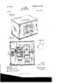
- Figure 1 is a perspective view of a clock or time-indicator embodying my improvements.
- Fig. 2 is a central vertical section of the case, showing the clock-movement at one side of the case and part of the works in section and part in elevation.
- Fig. 3 is a view similar to Fig. 2, showing the clock-movement located centrally in the case and between the hour and minute indicating devices.
- Fig. 4 is a transverse sectional view looking toward the side of the indicating device; and Fig. 5 represents one of the indicating-plates detached, showing one way in which they may be suitably made.
- any suitable ordinary clock-movement may be used, as shown at a in Fig. 2, where the movement is located at one side of the hour and minute indicating devices, and at a in Fig. 3, where the movement is located between the hour and minute indicating devices.
- the clock-movement is arranged with its minute-spindle horizontal,but parallel with the front of the clock. Only so much of the clock-movement is shown as is necessary to afford a correct understanding of its combination with the other features of my invention.
- the hour-indicating plates 1) are marked or impressed with numbers toiudicate the hours, and the minute-indicating plates 0 are marked or impressed with numbers to indicate the minutes.
- Each of these plates is provided with two ears or projections, the projections b on the plates 1) and the projections c on the plates 0 entering perforationsin apairofdisks and by means of which each plate has a pivotal or hinged engagement with and is carried by such disks.
- the pair of disks d d carries the hour-indicating plates 5, and the pair of disks (2 e carries the minute-indicating plates 0.
- These disks are mounted on a common axis in alinement with the minute-spindle of the clock-movement. As shown in Fig.
- the minute-spindle f is prolonged to extend across the case and has its outer end supported in the bearing-piece h, secured to the end of the case opposite the clock-movement.
- the disks d, carrying the hour-indicating plates, are secured upon a shaft or sleeve j, which is loosely mounted on the minute-spindle, so as to rotate freely thereon.
- the disks e, carrying the minute-indicating plates, are suitably secured upon a shaft or sleeve 2', which is secured upon the minutespindle, so as to rotate therewith.
- the hourspindlej has secured upon it a gear 7.6, which through intermediate gears 10 is connected to and actuated by the pinion Z, secured upon the minute-spindle f, these gears being the' ordinary hou r-hand red ucing-gears of a clockmovement.
- a squared endf is provided on the minute-spindle for setting the plates in the same manner as setting the hands of a clock, and a ratchet and pawl m, shown at the other end of the minute-spindle, are provided to prevent moving the cards backward.
- the winding-shaft of the clock-movement is shown at 00 In the construction shown in Fig.
- the hour-shaft j has a hearing at one end on the lninute-spindlefand at the other end in the bearingpiece it on the clock-case and is connected to the minute-spindle by reducinggear 7c 70 Z, as in the construction shown in Fig. 2.
- the shaft 71 of the minute-indicating plates is coupled at one end to the minutespindlef, as by a pin '6 and at the other end is supported in a bearing-piece k and has a squared end f for setting the indicatorplates.
- a winding-spindle n is shown in Fig. 3, having a squared upper end a, and at its lowerend a bevel-pinion 0, this pinion 0 meshing into a bevel-wheel p, secured to the motor device of the clock-movement.
- the time-indicating plates will be sufficiently numerous to indicate by their suc cessive exposure intervals of time sufficiently short for all practical purposes, and the same number of plates is provided to indicate the minutes and hours.
- I have shown as a suitable number sixty plates in each series, the minute series being figured or lettered consecutively from 1 to 60 or from 1 to 59 and one blank, so that each minute of time will be indicated, and as the disks carrying the hour-plates will rotate onetwelfth of a revolution to each revolution of the minute-disks the hour-plates 0 will be divided into sections similarly figured or lettered successively from 1 to 12, as indicated by the numerals arranged around the plates 0 in Fig. 4.
- Each minute-indi cating plate will be exposed one minute and each hour-indicating plate will be exposed twelve minutes. It will be observed that two of the ten-hour plates are yet to fall, the time as indicated by the other views being ten hours forty-one minutes, and upon the passing of the sixty minutes then the last tenhour plate will fall and the first plate of the ,eleven-hour section will be exposed at the same time that the 1 or the blank plate of the minute series is exposed, according to the arrangement of the minute-plates, whether' they are to indicate the minutes lapsing or the minutes lapsed.
- the means for controlling the descent of the plates 17 and c as the carrying-disks rotate consist of the stops q and r, set in the front of the case or in brackets extending therefrom, against which stops the upper edges of the plates bear, as clearly shown at Figs. 1, 3, and 4, and from the lower ends of which stops the plates escape and fall over as the disks carrying the plates slowly rotate.
- these stops q and 1" adjustable To insure that the plates of the two sets shall fall in unison, it is desirable to make these stops q and 1" adjustable. To this end they are shown as fine-threaded screws, so that they may be readily and delicately set.
- a glass cover which may be of any suitable shape, preferably semicylindrical, as shown at s, with the ends formed integral therewith and provided with a flange s, by which it may be held in front of the case g.
- the means for holding this glass cover may be a light wooden frame .9 which may be permanently secured, as by screws, to the front of the case or be provided with hinges and a latch, as are ordinary clock-fronts.
- the time-indicating plates 1) and 0 may be made of cardboard, light metal, celluloid, or other suitable material and may have the pivoting-ears b and c as projections from one of their edges, as shown in the main views of the drawings, or the edges may be bound and reinforced by a metallic binding-strip t, as shown at Fig. 5, made somewhat longer than the edges of the plates, the projecting ends of which constitute the pivotal connections of the plates in their carrying-disks.
- the adaptation to a time-indicator of series of plates consecutively exposed provides an advantageous and suitable display apparatus, the display matter, whether simply pictures or advertisements, being printed upon or attached to the rear faces of the plates, thus exposing to view a new subject as each of the plates falls in chronometrical order.
- a time-indicator in combination, a clock-movement, two plate-carrying rotating parts mounted in axial alinement with each other and actuated by the clock-movement, a plurality of time-indicating plates carried by such rotating parts and pivotally mounted thereon, the time-indicating plates carried by one rotating part indicating minutes and the time-indicating plates carried by the other rotating part indicating hours and both rotating parts carrying the same number of p1ates,and stops arranged to successively coact with such plates to cause them to be successively exposed.
- a time-indicator in combination, a clock-movement, two plate-carrying rotating parts mounted in axial alinement with each other and with the minute-spindle of the clock, a plurality of time-indicating plates carried by such rotating parts and pivotally mounted thereon, the time-indicating plates carried by one rotating part indicating minutes and such rotating part being secured upon the minutespindle,and the time-indicating plates carried by the other rotating part indicating hours, reducing-gearin g whereby such other rotating part is actuated from the minute-spindle, each of such rotating parts carrying the same num ber of plates, and stops arranged to successively coact with such plates to cause them to be successively exposed.
Landscapes
- Physics & Mathematics (AREA)
- General Physics & Mathematics (AREA)
- Time Recorders, Dirve Recorders, Access Control (AREA)
Description
No. 715,776. r Patented Dec. I6, I902.
E. men.
TIME INDICATOR.
(Applieation flled Jan. 8, 1901.) (No lodol.) 2 Shuts-Sheet 2.
- \fll Uh! u k v 0 3 m v. 7 "a? I J M5 =6 6 g 8 I p?) WITNESSES: ,INVENTQR ATTORNEY m: Noam: Prints 00. Wou'mm. wsnmcwou. D. c
UNITED STATES PATENT OFFICE.
EUGENE FITCH, OF NEW YORK, N. Y.
TIM E-INDICATOR.
SPECIFICATION formingpart of Letters Patent No. 715,776, dated December 16, 1902- Application filed January 3,1901. Serial No. 41,942. (No model.)
To all whom, it may concern:
Beit known that I, EUGENE FITCH, acitizen of the United States, and a resident of New York, county and State of New York, have invented Improvements in Time-Indicators, of which the following is a specification.
This invention relates to time-indicators or clocks, and has for its object to provide improved means for successively exposing timeindicating plates.
According to my invention thetime-indieating plates are pivotally mounted upon rotating parts in axial alinement with each other and with the minute-spindle of the clockmove1nent,wherebya simple construction and direct actuation of these rotating parts are attained, and according to my invention the same number of minute-indicating plates and hour-indicating plates is employed on rotating parts in axial alinement with each other, permitting the employment of the ordinary honr hand reducing-gears to connect the two rotating parts and exhibiting the plates in the same plane and attaining a sufficiently frequent movement of the hour-indicating plates to afford the desired accuracy of exhibition without impracticable accuracy of construction.
I will now describe the constructions of time-indicators illustrated in the accompanying drawings and will thereafter point out my invention in claims.
Figure 1 is a perspective view of a clock or time-indicator embodying my improvements. Fig. 2 is a central vertical section of the case, showing the clock-movement at one side of the case and part of the works in section and part in elevation. Fig. 3 is a view similar to Fig. 2, showing the clock-movement located centrally in the case and between the hour and minute indicating devices. Fig. 4 is a transverse sectional view looking toward the side of the indicating device; and Fig. 5 represents one of the indicating-plates detached, showing one way in which they may be suitably made.
Any suitable ordinary clock-movement may be used, as shown at a in Fig. 2, where the movement is located at one side of the hour and minute indicating devices, and at a in Fig. 3, where the movement is located between the hour and minute indicating devices. In both of these constructions the clock-movement is arranged with its minute-spindle horizontal,but parallel with the front of the clock. Only so much of the clock-movement is shown as is necessary to afford a correct understanding of its combination with the other features of my invention.
The hour-indicating plates 1) are marked or impressed with numbers toiudicate the hours, and the minute-indicating plates 0 are marked or impressed with numbers to indicate the minutes. Each of these plates is provided with two ears or projections, the projections b on the plates 1) and the projections c on the plates 0 entering perforationsin apairofdisks and by means of which each plate has a pivotal or hinged engagement with and is carried by such disks. The pair of disks d d carries the hour-indicating plates 5, and the pair of disks (2 e carries the minute-indicating plates 0. These disks are mounted on a common axis in alinement with the minute-spindle of the clock-movement. As shown in Fig. 2, the minute-spindle f is prolonged to extend across the case and has its outer end supported in the bearing-piece h, secured to the end of the case opposite the clock-movement. The disks d, carrying the hour-indicating plates, are secured upon a shaft or sleeve j, which is loosely mounted on the minute-spindle, so as to rotate freely thereon. The disks e, carrying the minute-indicating plates, are suitably secured upon a shaft or sleeve 2', which is secured upon the minutespindle, so as to rotate therewith. The hourspindlej has secured upon it a gear 7.6, which through intermediate gears 10 is connected to and actuated by the pinion Z, secured upon the minute-spindle f, these gears being the' ordinary hou r-hand red ucing-gears of a clockmovement. A squared endf is provided on the minute-spindle for setting the plates in the same manner as setting the hands of a clock, and a ratchet and pawl m, shown at the other end of the minute-spindle, are provided to prevent moving the cards backward. The winding-shaft of the clock-movement is shown at 00 In the construction shown in Fig. 3 the hour-shaft j has a hearing at one end on the lninute-spindlefand at the other end in the bearingpiece it on the clock-case and is connected to the minute-spindle by reducinggear 7c 70 Z, as in the construction shown in Fig. 2. The shaft 71 of the minute-indicating plates is coupled at one end to the minutespindlef, as by a pin '6 and at the other end is supported in a bearing-piece k and has a squared end f for setting the indicatorplates.
A winding-spindle n is shown in Fig. 3, having a squared upper end a, and at its lowerend a bevel-pinion 0, this pinion 0 meshing into a bevel-wheel p, secured to the motor device of the clock-movement.
The time-indicating plates will be sufficiently numerous to indicate by their suc cessive exposure intervals of time sufficiently short for all practical purposes, and the same number of plates is provided to indicate the minutes and hours. I have shown as a suitable number sixty plates in each series, the minute series being figured or lettered consecutively from 1 to 60 or from 1 to 59 and one blank, so that each minute of time will be indicated, and as the disks carrying the hour-plates will rotate onetwelfth of a revolution to each revolution of the minute-disks the hour-plates 0 will be divided into sections similarly figured or lettered successively from 1 to 12, as indicated by the numerals arranged around the plates 0 in Fig. 4. Each minute-indi cating plate will be exposed one minute and each hour-indicating plate will be exposed twelve minutes. It will be observed that two of the ten-hour plates are yet to fall, the time as indicated by the other views being ten hours forty-one minutes, and upon the passing of the sixty minutes then the last tenhour plate will fall and the first plate of the ,eleven-hour section will be exposed at the same time that the 1 or the blank plate of the minute series is exposed, according to the arrangement of the minute-plates, whether' they are to indicate the minutes lapsing or the minutes lapsed. The means for controlling the descent of the plates 17 and c as the carrying-disks rotate consist of the stops q and r, set in the front of the case or in brackets extending therefrom, against which stops the upper edges of the plates bear, as clearly shown at Figs. 1, 3, and 4, and from the lower ends of which stops the plates escape and fall over as the disks carrying the plates slowly rotate. To insure that the plates of the two sets shall fall in unison, it is desirable to make these stops q and 1" adjustable. To this end they are shown as fine-threaded screws, so that they may be readily and delicately set.
To fully protect all of the works, it is proposed to inclose the semicircular space through which the plates 5 and a fall, they being arranged as near the front of the case 9 as possible by a glass cover, which may be of any suitable shape, preferably semicylindrical, as shown at s, with the ends formed integral therewith and provided with a flange s, by which it may be held in front of the case g. The means for holding this glass cover may be a light wooden frame .9 which may be permanently secured, as by screws, to the front of the case or be provided with hinges and a latch, as are ordinary clock-fronts.
The time-indicating plates 1) and 0 may be made of cardboard, light metal, celluloid, or other suitable material and may have the pivoting-ears b and c as projections from one of their edges, as shown in the main views of the drawings, or the edges may be bound and reinforced by a metallic binding-strip t, as shown at Fig. 5, made somewhat longer than the edges of the plates, the projecting ends of which constitute the pivotal connections of the plates in their carrying-disks.
The adaptation to a time-indicator of series of plates consecutively exposed provides an advantageous and suitable display apparatus, the display matter, whether simply pictures or advertisements, being printed upon or attached to the rear faces of the plates, thus exposing to view a new subject as each of the plates falls in chronometrical order.
It is obvious that various modifications may be made in the constructions above particularly described within the spirit and scope of my invention.
What I claim, and desire to secure by Letters Patent, is
1. In a time-indicator, in combination, a clock-movement, two plate-carrying rotating parts mounted in axial alinement with each other and actuated by the clock-movement, a plurality of time-indicating plates carried by such rotating parts and pivotally mounted thereon, the time-indicating plates carried by one rotating part indicating minutes and the time-indicating plates carried by the other rotating part indicating hours and both rotating parts carrying the same number of p1ates,and stops arranged to successively coact with such plates to cause them to be successively exposed.
2. In a time-indicator, in combination, a clock-movement, two plate-carrying rotating parts mounted in axial alinement with each other and with the minute-spindle of the clock, a plurality of time-indicating plates carried by such rotating parts and pivotally mounted thereon, the time-indicating plates carried by one rotating part indicating minutes and such rotating part being secured upon the minutespindle,and the time-indicating plates carried by the other rotating part indicating hours, reducing-gearin g whereby such other rotating part is actuated from the minute-spindle, each of such rotating parts carrying the same num ber of plates, and stops arranged to successively coact with such plates to cause them to be successively exposed.
In testimony whereof I have hereunto subscribed my name this 27th day of December, 1900.
EUGENE FITCH.
Witnesses:
ARTHUR C. BLATZ, HERMAN MARSCHALL.
IIO
Priority Applications (1)
| Application Number | Priority Date | Filing Date | Title |
|---|---|---|---|
| US4194201A US715776A (en) | 1901-01-03 | 1901-01-03 | Time-indicator. |
Applications Claiming Priority (1)
| Application Number | Priority Date | Filing Date | Title |
|---|---|---|---|
| US4194201A US715776A (en) | 1901-01-03 | 1901-01-03 | Time-indicator. |
Publications (1)
| Publication Number | Publication Date |
|---|---|
| US715776A true US715776A (en) | 1902-12-16 |
Family
ID=2784296
Family Applications (1)
| Application Number | Title | Priority Date | Filing Date |
|---|---|---|---|
| US4194201A Expired - Lifetime US715776A (en) | 1901-01-03 | 1901-01-03 | Time-indicator. |
Country Status (1)
| Country | Link |
|---|---|
| US (1) | US715776A (en) |
Cited By (7)
| Publication number | Priority date | Publication date | Assignee | Title |
|---|---|---|---|---|
| US2545362A (en) * | 1945-10-31 | 1951-03-13 | Seeburg J P Corp | Index for selective automatic phonographs |
| US2576119A (en) * | 1945-05-28 | 1951-11-27 | Holzner Adolf | Wall and desk cyclometer clock |
| US2687003A (en) * | 1951-06-12 | 1954-08-24 | Junghans Geb Ag | Clock |
| US2762190A (en) * | 1945-05-28 | 1956-09-11 | Holzner Adolf | Cyclometer clock system |
| US3220174A (en) * | 1963-03-06 | 1965-11-30 | Enrico Boselli S P A | Springless, tilting plates clock driven by two oval gears |
| US3645087A (en) * | 1969-05-20 | 1972-02-29 | Braun Ag | Digital clock with additional data indication |
| US4182071A (en) * | 1977-12-06 | 1980-01-08 | Masatoshi Todokoro | Toy television set |
-
1901
- 1901-01-03 US US4194201A patent/US715776A/en not_active Expired - Lifetime
Cited By (7)
| Publication number | Priority date | Publication date | Assignee | Title |
|---|---|---|---|---|
| US2576119A (en) * | 1945-05-28 | 1951-11-27 | Holzner Adolf | Wall and desk cyclometer clock |
| US2762190A (en) * | 1945-05-28 | 1956-09-11 | Holzner Adolf | Cyclometer clock system |
| US2545362A (en) * | 1945-10-31 | 1951-03-13 | Seeburg J P Corp | Index for selective automatic phonographs |
| US2687003A (en) * | 1951-06-12 | 1954-08-24 | Junghans Geb Ag | Clock |
| US3220174A (en) * | 1963-03-06 | 1965-11-30 | Enrico Boselli S P A | Springless, tilting plates clock driven by two oval gears |
| US3645087A (en) * | 1969-05-20 | 1972-02-29 | Braun Ag | Digital clock with additional data indication |
| US4182071A (en) * | 1977-12-06 | 1980-01-08 | Masatoshi Todokoro | Toy television set |
Similar Documents
| Publication | Publication Date | Title |
|---|---|---|
| US715776A (en) | Time-indicator. | |
| US2535543A (en) | Geographical multiple dial watch | |
| US410327A (en) | meylan | |
| US410967A (en) | School | |
| US222377A (en) | Improvement in calendar-clocks | |
| US1275791A (en) | Clock mechanism. | |
| US2014168A (en) | Calendar clock | |
| US781505A (en) | Timepiece. | |
| US701853A (en) | Geographical timepiece. | |
| US693953A (en) | Geographical clock. | |
| US317380A (en) | Frederick a | |
| US1089712A (en) | Automatic reminder. | |
| US424185A (en) | Lewis donne and morgan donne | |
| US755969A (en) | Clock-dial. | |
| US1204732A (en) | Advertising-clock. | |
| US1153038A (en) | Timepiece. | |
| US309306A (en) | lindauer | |
| KR102457850B1 (en) | Timepiece comprising am-pm indicating means | |
| US657117A (en) | Geographical clock. | |
| US651850A (en) | Program-clock. | |
| US576528A (en) | Alarm-clock | |
| US82266A (en) | Improvement in clocks | |
| US448510A (en) | dubois | |
| US724460A (en) | Clock. | |
| US716166A (en) | Calendar. |