US7157664B2 - Laser heater assembly - Google Patents
Laser heater assembly Download PDFInfo
- Publication number
- US7157664B2 US7157664B2 US11/092,520 US9252005A US7157664B2 US 7157664 B2 US7157664 B2 US 7157664B2 US 9252005 A US9252005 A US 9252005A US 7157664 B2 US7157664 B2 US 7157664B2
- Authority
- US
- United States
- Prior art keywords
- laser
- heater
- transistor
- temperature
- assembly
- Prior art date
- Legal status (The legal status is an assumption and is not a legal conclusion. Google has not performed a legal analysis and makes no representation as to the accuracy of the status listed.)
- Expired - Fee Related
Links
- 238000010438 heat treatment Methods 0.000 claims description 9
- 239000000835 fiber Substances 0.000 claims description 8
- 239000004020 conductor Substances 0.000 claims description 3
- 230000001419 dependent effect Effects 0.000 description 3
- 230000003287 optical effect Effects 0.000 description 2
- 229910052782 aluminium Inorganic materials 0.000 description 1
- XAGFODPZIPBFFR-UHFFFAOYSA-N aluminium Chemical compound [Al] XAGFODPZIPBFFR-UHFFFAOYSA-N 0.000 description 1
- 230000009286 beneficial effect Effects 0.000 description 1
- 230000015556 catabolic process Effects 0.000 description 1
- 238000006731 degradation reaction Methods 0.000 description 1
- 238000010586 diagram Methods 0.000 description 1
- 239000004519 grease Substances 0.000 description 1
- 229910052751 metal Inorganic materials 0.000 description 1
- 239000002184 metal Substances 0.000 description 1
- 238000005070 sampling Methods 0.000 description 1
- 229920006395 saturated elastomer Polymers 0.000 description 1
- 230000003068 static effect Effects 0.000 description 1
Images


Classifications
-
- H—ELECTRICITY
- H01—ELECTRIC ELEMENTS
- H01S—DEVICES USING THE PROCESS OF LIGHT AMPLIFICATION BY STIMULATED EMISSION OF RADIATION [LASER] TO AMPLIFY OR GENERATE LIGHT; DEVICES USING STIMULATED EMISSION OF ELECTROMAGNETIC RADIATION IN WAVE RANGES OTHER THAN OPTICAL
- H01S5/00—Semiconductor lasers
- H01S5/02—Structural details or components not essential to laser action
- H01S5/024—Arrangements for thermal management
- H01S5/02453—Heating, e.g. the laser is heated for stabilisation against temperature fluctuations of the environment
-
- H—ELECTRICITY
- H01—ELECTRIC ELEMENTS
- H01S—DEVICES USING THE PROCESS OF LIGHT AMPLIFICATION BY STIMULATED EMISSION OF RADIATION [LASER] TO AMPLIFY OR GENERATE LIGHT; DEVICES USING STIMULATED EMISSION OF ELECTROMAGNETIC RADIATION IN WAVE RANGES OTHER THAN OPTICAL
- H01S5/00—Semiconductor lasers
- H01S5/06—Arrangements for controlling the laser output parameters, e.g. by operating on the active medium
- H01S5/068—Stabilisation of laser output parameters
- H01S5/06804—Stabilisation of laser output parameters by monitoring an external parameter, e.g. temperature
-
- H—ELECTRICITY
- H01—ELECTRIC ELEMENTS
- H01S—DEVICES USING THE PROCESS OF LIGHT AMPLIFICATION BY STIMULATED EMISSION OF RADIATION [LASER] TO AMPLIFY OR GENERATE LIGHT; DEVICES USING STIMULATED EMISSION OF ELECTROMAGNETIC RADIATION IN WAVE RANGES OTHER THAN OPTICAL
- H01S5/00—Semiconductor lasers
- H01S5/02—Structural details or components not essential to laser action
- H01S5/022—Mountings; Housings
- H01S5/02208—Mountings; Housings characterised by the shape of the housings
- H01S5/02212—Can-type, e.g. TO-CAN housings with emission along or parallel to symmetry axis
Definitions
- the present invention relates to lasers and, more particularly, relates to maintaining the laser at a constant temperature by heating the laser.
- the case temperature of an operating laser is substantially equivalent to ambient temperature.
- the case temperature can be quite extreme. Outside temperatures may reach as cold as ⁇ 40 degrees Celsius.
- laser performance characteristics are very dependent upon operating case temperature. Not only do parameters such as slope efficiency and output power vary with operating temperature, but output wavelength varies as well. This can cause issues if the laser output wavelength drifts outside of the bandwidth of the combining and splitting optical passives in the network. Therefore, it is desirable to maintain the laser at as constant a temperature as possible or at least within a range that the device is designed to operate within. What is needed is an economical means to minimize performance degradation due to cold temperatures and to extend the lowest temperature a laser can operate at.
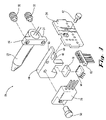
- FIG. 1 illustrates a perspective view of one embodiment of a thermostatically controlled heater assembly of the present invention.
- FIG. 2 illustrates a perspective view of the heater assembly of FIG. 1 utilized in an optical transmitter of a CATV node.
- FIG. 3 illustrates an exploded view of the heater assembly of FIG. 1 .
- FIG. 4 illustrates a generalized block diagram of one embodiment of the present invention.
- FIG. 5 illustrates one embodiment of a controller circuit for controlling the temperature of a laser according to the present invention.
- FIG. 6 illustrates one embodiment of a temperature dependent laser enable circuit according to the present invention.
- FIG. 1 illustrates one embodiment of a thermoelectric heater assembly 10 of the present invention.
- the heater assembly 10 of FIG. 1 is utilized, for example, in a CATV node as a coarse wave division multiplexing (CWDM) reverse transmitter 12 as shown in FIG. 2 .
- the transmitter 12 includes a top cover 14 and a bottom cover 16 for housing a transmitter printed circuit board 18 with fiber optic cable having a fiber connector 20 .
- the heater assembly 10 may be implemented as part of other laser designs where it is desirable to reduce the overall temperature range that a laser must efficiently operate at and where an economical solution is desired.
- FIG. 3 illustrates an exploded view of the heater assembly 10 of FIG. 1 .
- the heater assembly 10 includes a laser 22 adapted to be electrically and mechanically coupled to a laser printed circuit board 24 as shown in FIG. 1 .
- the heater assembly 10 also includes a heating element or heater such as heater transistor 30 which is also electrically and mechanically coupled to the circuit board 24 .
- a thermal transfer member or heat sink such as a metal plate or block 40 , is positioned in between the mounted laser 22 and heater transistor 30 as best shown in FIG. 1 .
- the heater transistor 30 and the laser 22 directly abut opposite sides of the block 40 for the best thermal connection. Heat generated from the transistor 30 is directly absorbed by the block 40 and then transferred to the laser 22 . Therefore, the laser 22 is indirectly heated by the transistor 30 external to the laser 22 .
- the block 40 is preferably thin aluminum to facilitate transferring heat from the heater transistor 30 to the laser 22 through low thermal impedance and to minimize heating delay through thermal mass.
- the block 40 may be mechanically coupled to the circuit board 24 with a fastener such as screw 42 which is received in opening 44 defined between protruding portion 46 and protruding portion 48 of the block 40 .
- a fastener such as screw 42 which is received in opening 44 defined between protruding portion 46 and protruding portion 48 of the block 40 .
- other means for mechanically securing the block 40 to the circuit board 24 exist depending on the type and configuration of the thermal transfer plate or heat sink used.
- the block 40 may also be mechanically secured to a printed circuit board 18 of the transmitter 12 .
- the circuit board 24 and the block 40 are preferably mounted in substantially a vertical manner on the circuit board 18 of the transmitter 12 in order to lift the laser 22 and the transistor 30 away from the circuit board 18 to economize the space on the circuit board 18 .
- the laser 22 is directly mounted to the block 40 with mechanical fasteners such as screws 52 through laser flange members 54 as best shown in FIG. 3 .
- the heater transistor 30 is directly mounted to the block 40 with a mechanical fastener such as a screw 58 .
- other means of securing the laser 22 and the heater transistor 30 to the block 40 may be used.
- the laser assembly 10 may include a right angle header 62 to electrically couple the circuit board 24 to the circuit board 18 of the transmitter 12 .
- the laser assembly may also include a temperature sensor 66 positioned underneath the block 40 and electrically coupled to the circuit board 18 .
- the temperature sensor 66 measures the temperature of the block 40 , and thus the temperature of the laser 22 , and feeds this information to the heater controller describer below.
- a thermally conductive material such as grease or a thermal pad 70 is used between the block 40 and the sensor 66 to improve thermal conductivity as well as absorb any dimensional tolerances between the block 40 and the temperature sensor 66 .
- FIG. 4 illustrates in a generalized manner the laser 22 with thermal connections to the heater transistor 30 and the temperature sensor 66 .
- the temperature sensor measures the temperature of the laser 22 and feeds this information as an input to a heater control circuit 76 .
- the heater control circuit 76 determines whether to increase or decrease the amount of heating.
- the output of the heater control circuit 76 is fed to the heater transistor 30 which produces heat in proportion to the control signal from the heater control circuit 76 .
- FIG. 5 illustrates one embodiment of the heater control circuit 76 having controller circuitry 78 and voltage to current converter circuitry 80 .
- the controller circuitry 78 of the heater control circuit 76 includes a controller 82 .
- the controller 82 compares the temperature measured by the temperature sensor 66 to a desired set point temperature and produces an output voltage that produces more or less heat in an effort to make the temperature of the block 40 equal to the set point temperature.
- the heater transistor 30 will turn off and becomes passive until the ambient temperature drops back below the set point temperature.
- the controller 82 may be an integrating or proportional controller, or both. If an integrating controller is selected, the time constant of the integrator must be set long enough to compensate for thermal lag due to heating the block 40 and the laser 22 . Proportional controllers have the advantage of less settling time, but may have a static error between laser temperature and set point temperature the magnitude of which is dependent on loop gain.
- the controller 82 has two inputs, a reference voltage (REF) produced by a resistive divider on the positive input, and the output of the temperature sensor 66 on the negative input.
- the temperature sensor 66 is input to the controller 82 through an input resistor 68 with feedback provided from the output to the negative input through impedance 84 .
- the output voltage of the controller 82 is used to drive the heater transistor 30 and is proportional to the amount of heat generated in the heater transistor 30 .
- the controller 82 output voltage is scaled through a simple voltage divider to ground provided by resistors 86 and 88 .
- the output of the voltage divider is connected to the noninverting input of op amp 90 .
- the output of op amp 90 is connected to the base of transistor 92 through resistor 94 .
- transistor 92 is not required but can be used if needed to drive the heater transistor 30 . If the heater transistor 30 is a BJT transistor and if either op amp 90 has a low drive current or the gain, ⁇ , of the heater transistor 30 is low, transistor 92 may be used for additional current gain. This is accomplished by connecting transistor 92 and transistor 30 in the Darlington configuration in which the emitter of transistter 92 connects to the base of the heater transistor 30 and the collectors of both transistors 30 , 92 are connected to the voltage supply Vcc. Current passing through heater transistor 30 produces the desired heat and is measured by the voltage created by passing the current of the heater transistor 30 through a current sampling resister 96 .
- Negative feedback from resistor 98 is provided to op amp 90 through resistor 98 .
- Heat produced by the heater transistor 30 is conducted to the laser 22 through the thermal connection provided by the block 30 which conducts heat to the temperature sensor 66 that feeds a signal back to the controller 82 as described above.
- FIG. 6 illustrates one embodiment of a temperature based enable circuit 110 , commonly referred to as a comparator circuit, for use with the laser assembly 10 and the control circuit 76 .
- the circuit 110 precludes the laser 22 from turning on until the temperature of the laser 22 is above the set point temperature.
- a simple comparator circuit can be used to pull the laser power control loop reference to a voltage which will force laser output power to zero.
- the temperature based enable circuit 110 includes a comparator 120 which monitors and compares input voltages from a reference trip point and the output of the temperature sensor 66 .
- the reference trip point voltage is set by the resistive divider of resistor 122 and resistor 124 .
- the output of comparator 120 is indicative of whether the temperature of laser 22 is above or below the reference trip point.
- the gate of a transistor 130 is driven by the output of comparator 120 through resistor 132 allowing transistor 130 to function as a switch.
- the switch function of transistor 130 acts upon the laser power control loop reference, Vref, of the integrator circuit 140 .
- the laser power control loop reference voltage, Vref When the transistor 130 is “ON”, or saturated, the laser power control loop reference voltage, Vref, is brought to zero volts or slightly negative which forces the laser power to zero.
- the Vref voltage when transistor 130 is “ON” is shifted by the value of Vee and the resistor 134 .
- the Vref voltage when the transistor 130 is “OFF” is set by the voltage divider of resistors 136 and 138 from Vcc. Turning transistor 130 on and off effectively changes the reference voltage of the circuit that controls laser output power.
Landscapes
- Physics & Mathematics (AREA)
- Condensed Matter Physics & Semiconductors (AREA)
- General Physics & Mathematics (AREA)
- Electromagnetism (AREA)
- Optics & Photonics (AREA)
- Semiconductor Lasers (AREA)
Abstract
Description
Claims (13)
Priority Applications (1)
| Application Number | Priority Date | Filing Date | Title |
|---|---|---|---|
| US11/092,520 US7157664B2 (en) | 2005-03-29 | 2005-03-29 | Laser heater assembly |
Applications Claiming Priority (1)
| Application Number | Priority Date | Filing Date | Title |
|---|---|---|---|
| US11/092,520 US7157664B2 (en) | 2005-03-29 | 2005-03-29 | Laser heater assembly |
Publications (2)
| Publication Number | Publication Date |
|---|---|
| US20060219687A1 US20060219687A1 (en) | 2006-10-05 |
| US7157664B2 true US7157664B2 (en) | 2007-01-02 |
Family
ID=37069070
Family Applications (1)
| Application Number | Title | Priority Date | Filing Date |
|---|---|---|---|
| US11/092,520 Expired - Fee Related US7157664B2 (en) | 2005-03-29 | 2005-03-29 | Laser heater assembly |
Country Status (1)
| Country | Link |
|---|---|
| US (1) | US7157664B2 (en) |
Cited By (2)
| Publication number | Priority date | Publication date | Assignee | Title |
|---|---|---|---|---|
| USRE46384E1 (en) * | 2008-01-18 | 2017-05-02 | Bliss Holdings, Llc | Laser lighting apparatus with heatsink housing |
| USD832803S1 (en) | 2016-12-06 | 2018-11-06 | Arris Enterprises Llc | Heater assembly for a laser diode |
Families Citing this family (2)
| Publication number | Priority date | Publication date | Assignee | Title |
|---|---|---|---|---|
| JP2003142674A (en) | 2001-11-07 | 2003-05-16 | Toshiba Corp | MOS type solid-state imaging device |
| WO2007015710A2 (en) * | 2004-11-09 | 2007-02-08 | Board Of Regents, The University Of Texas System | The fabrication and application of nanofiber ribbons and sheets and twisted and non-twisted nanofiber yarns |
Citations (2)
| Publication number | Priority date | Publication date | Assignee | Title |
|---|---|---|---|---|
| US20030161593A1 (en) * | 2002-02-27 | 2003-08-28 | Optronx, Inc. | Thermal pads for surface mounting of optical devices |
| US6677555B2 (en) * | 2001-01-30 | 2004-01-13 | Samsung Electronics Co., Ltd. | Optical device module using integral heat transfer module |
-
2005
- 2005-03-29 US US11/092,520 patent/US7157664B2/en not_active Expired - Fee Related
Patent Citations (2)
| Publication number | Priority date | Publication date | Assignee | Title |
|---|---|---|---|---|
| US6677555B2 (en) * | 2001-01-30 | 2004-01-13 | Samsung Electronics Co., Ltd. | Optical device module using integral heat transfer module |
| US20030161593A1 (en) * | 2002-02-27 | 2003-08-28 | Optronx, Inc. | Thermal pads for surface mounting of optical devices |
Cited By (2)
| Publication number | Priority date | Publication date | Assignee | Title |
|---|---|---|---|---|
| USRE46384E1 (en) * | 2008-01-18 | 2017-05-02 | Bliss Holdings, Llc | Laser lighting apparatus with heatsink housing |
| USD832803S1 (en) | 2016-12-06 | 2018-11-06 | Arris Enterprises Llc | Heater assembly for a laser diode |
Also Published As
| Publication number | Publication date |
|---|---|
| US20060219687A1 (en) | 2006-10-05 |
Similar Documents
| Publication | Publication Date | Title |
|---|---|---|
| US6094918A (en) | Thermoelectric cooler control circuit | |
| US5088098A (en) | Thermoelectric cooler control circuit | |
| US8079222B2 (en) | Thermoelectric cooler controller | |
| US5704213A (en) | Method and apparatus for controlling the temperature of a device using independent multi-stage thermoelectric coolers | |
| US6584128B2 (en) | Thermoelectric cooler driver utilizing unipolar pulse width modulated synchronous rectifiers | |
| US5740191A (en) | Wide temperature range uncooled lightwave transmitter having a heated laser | |
| US6725669B2 (en) | Thermoelectric cooler temperature control | |
| US5602860A (en) | Laser thermal control using thermoelectric cooler | |
| JPH0728077B2 (en) | Semiconductor laser oscillation frequency / oscillation output stabilizer | |
| CN108666856A (en) | Power stable solid-state laser and control method | |
| US20030033819A1 (en) | Current-Mode control of Thermo-Electric cooler | |
| US7157664B2 (en) | Laser heater assembly | |
| US7050673B2 (en) | Temperature control device and arrayed waveguide grating optical wavelength multiplexer/demultiplexer | |
| US20090139972A1 (en) | Docking connector | |
| JP2004207666A (en) | Laser diode module, laser diode device and optical transmitter | |
| CN201097244Y (en) | Temperature control device for tuning laser | |
| US20060237436A1 (en) | Laser heater controller | |
| EP0395259A2 (en) | Temperature control system for solid state light source | |
| CN114063679A (en) | TEC control circuit, control method thereof and temperature control device | |
| US7081712B2 (en) | Thermal cooler for a laser diode package | |
| KR101122858B1 (en) | Temperature tuning the wavelength of a semiconductor laser using a variable thermal impedance | |
| US7251261B2 (en) | Temperature tuning the wavelength of a semiconductor laser using a variable thermal impedance | |
| US20060262818A1 (en) | Microcontroller based thermoelectric cooler controller | |
| US11258228B2 (en) | Optical communication module | |
| JP2006114774A (en) | Wavelength stabilized semiconductor laser device |
Legal Events
| Date | Code | Title | Description |
|---|---|---|---|
| AS | Assignment |
Owner name: SCIENTIFIC-ATLANTA, INC., A CORP. OF GEORGIA, GEOR Free format text: ASSIGNMENT OF ASSIGNORS INTEREST;ASSIGNORS:MAHONEY, WILLIAM G.;BEST, BRYANT A.;REEL/FRAME:016449/0665 Effective date: 20050329 |
|
| FPAY | Fee payment |
Year of fee payment: 4 |
|
| FPAY | Fee payment |
Year of fee payment: 8 |
|
| AS | Assignment |
Owner name: SCIENTIFIC-ATLANTA, LLC, GEORGIA Free format text: CHANGE OF NAME;ASSIGNOR:SCIENTIFIC-ATLANTA, INC.;REEL/FRAME:034299/0440 Effective date: 20081205 Owner name: CISCO TECHNOLOGY, INC., CALIFORNIA Free format text: ASSIGNMENT OF ASSIGNORS INTEREST;ASSIGNOR:SCIENTIFIC-ATLANTA, LLC;REEL/FRAME:034300/0001 Effective date: 20141118 |
|
| FEPP | Fee payment procedure |
Free format text: MAINTENANCE FEE REMINDER MAILED (ORIGINAL EVENT CODE: REM.); ENTITY STATUS OF PATENT OWNER: LARGE ENTITY |
|
| LAPS | Lapse for failure to pay maintenance fees |
Free format text: PATENT EXPIRED FOR FAILURE TO PAY MAINTENANCE FEES (ORIGINAL EVENT CODE: EXP.); ENTITY STATUS OF PATENT OWNER: LARGE ENTITY |
|
| STCH | Information on status: patent discontinuation |
Free format text: PATENT EXPIRED DUE TO NONPAYMENT OF MAINTENANCE FEES UNDER 37 CFR 1.362 |
|
| FP | Lapsed due to failure to pay maintenance fee |
Effective date: 20190102 |