US7155916B2 - Supply unit cooling - Google Patents
Supply unit cooling Download PDFInfo
- Publication number
- US7155916B2 US7155916B2 US10/675,006 US67500603A US7155916B2 US 7155916 B2 US7155916 B2 US 7155916B2 US 67500603 A US67500603 A US 67500603A US 7155916 B2 US7155916 B2 US 7155916B2
- Authority
- US
- United States
- Prior art keywords
- cooling fluid
- unit
- fuel cell
- cell system
- supply device
- Prior art date
- Legal status (The legal status is an assumption and is not a legal conclusion. Google has not performed a legal analysis and makes no representation as to the accuracy of the status listed.)
- Expired - Lifetime, expires
Links
Images


Classifications
-
- H—ELECTRICITY
- H01—ELECTRIC ELEMENTS
- H01M—PROCESSES OR MEANS, e.g. BATTERIES, FOR THE DIRECT CONVERSION OF CHEMICAL ENERGY INTO ELECTRICAL ENERGY
- H01M8/00—Fuel cells; Manufacture thereof
- H01M8/04—Auxiliary arrangements, e.g. for control of pressure or for circulation of fluids
- H01M8/04082—Arrangements for control of reactant parameters, e.g. pressure or concentration
- H01M8/04089—Arrangements for control of reactant parameters, e.g. pressure or concentration of gaseous reactants
- H01M8/04111—Arrangements for control of reactant parameters, e.g. pressure or concentration of gaseous reactants using a compressor turbine assembly
-
- F—MECHANICAL ENGINEERING; LIGHTING; HEATING; WEAPONS; BLASTING
- F04—POSITIVE - DISPLACEMENT MACHINES FOR LIQUIDS; PUMPS FOR LIQUIDS OR ELASTIC FLUIDS
- F04D—NON-POSITIVE-DISPLACEMENT PUMPS
- F04D23/00—Other rotary non-positive-displacement pumps
- F04D23/008—Regenerative pumps
-
- F—MECHANICAL ENGINEERING; LIGHTING; HEATING; WEAPONS; BLASTING
- F04—POSITIVE - DISPLACEMENT MACHINES FOR LIQUIDS; PUMPS FOR LIQUIDS OR ELASTIC FLUIDS
- F04D—NON-POSITIVE-DISPLACEMENT PUMPS
- F04D25/00—Pumping installations or systems
- F04D25/02—Units comprising pumps and their driving means
- F04D25/06—Units comprising pumps and their driving means the pump being electrically driven
-
- F—MECHANICAL ENGINEERING; LIGHTING; HEATING; WEAPONS; BLASTING
- F04—POSITIVE - DISPLACEMENT MACHINES FOR LIQUIDS; PUMPS FOR LIQUIDS OR ELASTIC FLUIDS
- F04D—NON-POSITIVE-DISPLACEMENT PUMPS
- F04D29/00—Details, component parts, or accessories
- F04D29/58—Cooling; Heating; Diminishing heat transfer
- F04D29/5806—Cooling the drive system
-
- F—MECHANICAL ENGINEERING; LIGHTING; HEATING; WEAPONS; BLASTING
- F04—POSITIVE - DISPLACEMENT MACHINES FOR LIQUIDS; PUMPS FOR LIQUIDS OR ELASTIC FLUIDS
- F04D—NON-POSITIVE-DISPLACEMENT PUMPS
- F04D29/00—Details, component parts, or accessories
- F04D29/58—Cooling; Heating; Diminishing heat transfer
- F04D29/582—Cooling; Heating; Diminishing heat transfer specially adapted for elastic fluid pumps
- F04D29/584—Cooling; Heating; Diminishing heat transfer specially adapted for elastic fluid pumps cooling or heating the machine
-
- H—ELECTRICITY
- H01—ELECTRIC ELEMENTS
- H01M—PROCESSES OR MEANS, e.g. BATTERIES, FOR THE DIRECT CONVERSION OF CHEMICAL ENERGY INTO ELECTRICAL ENERGY
- H01M8/00—Fuel cells; Manufacture thereof
- H01M8/06—Combination of fuel cells with means for production of reactants or for treatment of residues
- H01M8/0662—Treatment of gaseous reactants or gaseous residues, e.g. cleaning
- H01M8/0668—Removal of carbon monoxide or carbon dioxide
-
- H—ELECTRICITY
- H01—ELECTRIC ELEMENTS
- H01M—PROCESSES OR MEANS, e.g. BATTERIES, FOR THE DIRECT CONVERSION OF CHEMICAL ENERGY INTO ELECTRICAL ENERGY
- H01M8/00—Fuel cells; Manufacture thereof
- H01M8/04—Auxiliary arrangements, e.g. for control of pressure or for circulation of fluids
- H01M8/04007—Auxiliary arrangements, e.g. for control of pressure or for circulation of fluids related to heat exchange
- H01M8/04014—Heat exchange using gaseous fluids; Heat exchange by combustion of reactants
-
- H—ELECTRICITY
- H01—ELECTRIC ELEMENTS
- H01M—PROCESSES OR MEANS, e.g. BATTERIES, FOR THE DIRECT CONVERSION OF CHEMICAL ENERGY INTO ELECTRICAL ENERGY
- H01M8/00—Fuel cells; Manufacture thereof
- H01M8/04—Auxiliary arrangements, e.g. for control of pressure or for circulation of fluids
- H01M8/04007—Auxiliary arrangements, e.g. for control of pressure or for circulation of fluids related to heat exchange
- H01M8/04029—Heat exchange using liquids
-
- Y—GENERAL TAGGING OF NEW TECHNOLOGICAL DEVELOPMENTS; GENERAL TAGGING OF CROSS-SECTIONAL TECHNOLOGIES SPANNING OVER SEVERAL SECTIONS OF THE IPC; TECHNICAL SUBJECTS COVERED BY FORMER USPC CROSS-REFERENCE ART COLLECTIONS [XRACs] AND DIGESTS
- Y02—TECHNOLOGIES OR APPLICATIONS FOR MITIGATION OR ADAPTATION AGAINST CLIMATE CHANGE
- Y02E—REDUCTION OF GREENHOUSE GAS [GHG] EMISSIONS, RELATED TO ENERGY GENERATION, TRANSMISSION OR DISTRIBUTION
- Y02E60/00—Enabling technologies; Technologies with a potential or indirect contribution to GHG emissions mitigation
- Y02E60/30—Hydrogen technology
- Y02E60/50—Fuel cells
Definitions
- the present invention relates to hydrogen supply units, and more particularly to cooling of a hydrogen supply unit.
- Feed gas supply units for fuel cell systems generally include a control unit and a drive unit.
- the control unit includes a controller housed in an air-cooled housing.
- the motor unit includes cooling fluid channels and is cooled by a cooling fluid such as water.
- the bearings of the motor unit are not adequately cooled. Operation of the bearings at undesired temperatures results in an increase in the chance of bearing failure. Bearing failure can result in malfunction of the feed gas supply unit or complete failure of the feed gas supply unit.
- the present invention provides a supply device to circulate a fluid through a flow system.
- the supply device includes a control unit having a control housing defining a first channel in heat exchange relationship with a first cooling fluid flowing therethrough.
- a drive unit communicates with the control unit.
- the control unit controls operation of the drive unit.
- a supply unit is driven by the drive unit and induces fluid flow through the flow system.
- the first cooling fluid is water that draws heat from the control unit.
- the drive unit further comprises a drive housing defining a second channel in heat exchange relationship with a second cooling fluid flowing therethrough.
- the second cooling fluid is either water or a gas.
- the supply unit includes a supply housing defining a third channel in heat exchange relationship with a third cooling fluid flowing therethrough.
- the third cooling fluid draws away heat generated by the supply unit.
- the third cooling fluid is water.
- the supply unit is a compressor including an impeller, a suction and a discharge.
- the suction is connected to the flow system.
- the impeller draws a fluid from the flow system into the supply unit through the suction.
- the discharge is connected to the flow system. The impeller pushes fluid from the supply unit into the flow system through the discharge.
- FIG. 1 is a functional block diagram of a fuel cell system including a hydrogen supply unit
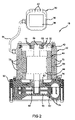
- FIG. 2 is a cross-sectional view of a water-cooled hydrogen supply unit
- FIG. 3 is a cross-sectional view of a water and gas cooled hydrogen supply unit
- FIG. 4 is a detailed view of a portion of the hydrogen supply unit of FIG. 3 ;
- FIG. 5 is a cross-sectional view of a water and gas cooled hydrogen supply unit having a controller attached thereto;
- FIG. 6 is a detailed view of a portion of the hydrogen supply unit of FIG. 5 ;
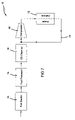
- FIG. 7 is a functional block diagram of a fuel cell system including a hydrogen supply unit and a recirculation loop for the hydrogen mixture.
- an exemplary fuel cell system 10 includes a fuel cell stack 12 .
- the fuel cell system 10 includes a fuel source 14 that provides fuel.
- Example fuels include, methanol, gasoline or other hydrocarbon fuels.
- a fuel processor 16 catalytically dissociates the hydrocarbon fuel into a hydrogen-rich reformate or hydrogen-containing feed gas that includes H 2 , CO 2 , H 2 O, and CO.
- the CO content of the feed gas is usually too high for use in the fuel cell stack 12 .
- the feed gas is treated by a CO clean-up device 18 .
- the CO clean-up device 18 includes a water-gas shift (WGS) reactor and a preferential oxidization (PO) reactor, although other CO clean-up devices 18 can be used.
- the feed gas is circulated through the fuel cell system 10 by a compressor 19 .
- a small amount of oxygen-rich air can be fed into the feed gas by a metering device 20 prior to the fuel cell stack 12 .
- the amount of air is generally less than 8% by volume. However, the amount of air may vary as design requirements dictate.
- the metering device 20 can include a variable orifice injector, a pulse-width modulated injector, a fixed displacement type injector or other suitable metering devices. Compressed air is provided to the metering device 20 by a compressor 22 and is heated by the heat of compression in the compressor 22 .
- the hydrogen-containing feed gas may be supplied directly from a hydrogen source (not shown).
- the hydrogen-containing feed gas is provided as pure hydrogen (H 2 ).
- the fuel processor 16 , CO clean-up device 18 and the metering device 20 are not required.
- the feed gas is circulated through the fuel cell system 10 by a compressor 19 directly from the hydrogen source.
- the system may also be provided with recirculation of the anode loop through a passage 23 .
- the passage 23 transports the anode exhaust from the stack 12 to the compressor 19 which increases the pressure and returns the anode gas to the stack 12 .
- Oxidant is supplied to the fuel cell stack 12 to catalytically react with the feed gas.
- the oxidant is oxygen-rich air supplied by the compressor 22 through a humidifier 24 .
- the humidified air is supplied to the fuel cell stack 12 through a regulator 26 to supply an appropriate air pressure.
- the compressor 19 includes a control unit 30 and a drive unit 32 .
- the control unit 30 communicates with the drive unit 32 by a cable 34 .
- the control unit 30 includes a housing 36 that encloses a controller 38 .
- a series of enclosed flow channels 40 are formed in walls of the housing 36 .
- the drive unit 32 includes a housing 42 , a motor 48 and an impeller 50 .
- the housing 42 defines an interior 52 , a series enclosed of flow channels and a compression chamber 56 .
- the impeller 50 is located within the compression chamber 56 . Feed gas is drawn into the compressor 19 through a suction inlet (not shown), is compressed within the compressor 19 and is discharged from the compressor 19 through a discharge outlet (not shown).
- the motor 48 includes a shaft 58 rotatably supported within the housing 42 by bearings 60 , 62 .
- the shaft 58 extends into the compression chamber 56 through a seal 64 .
- the seal 64 prevents the feed gas compressed within the compression chamber 56 from leaking into the motor 48 .
- a rotor 66 is fixed to the shaft 58 and is surrounded by a stator 68 .
- the stator 68 is fixed to the housing 42 .
- Current flowing through the stator windings induces eddy currents within the housing 42 .
- the eddy currents induce rotation of the rotor 66 and the shaft 58 .
- the impeller 50 is fixed for rotation with the shaft 58 .
- the impeller 50 compresses the feed gas within the compression chamber 56 as the shaft 58 is induced to rotate.
- the flow channels are formed through various “hot spot” areas of the housing 42 .
- a first series of flow channels 70 are formed around and are in heat exchange relationship with the stator 68 .
- Second and third series of flow channels 72 , 74 respectively, are formed around and are in heat exchange relationship with the bearings 60 , 62 .
- a fourth series of flow channels 76 is formed along and are in heat exchange relationship with the compression chamber 56 .
- a cooling fluid flows through the flow channels to cool the associated components. Cooling fluid flowing through the flow channels 40 of the control unit 30 cool the control unit 30 and the controller 38 in particular. This enables the controller 38 to operate at an optimum temperature and maximum efficiency. Cooling fluid flowing through the first, second and third series of flow channels 70 , 72 , 74 cools the motor components. This enables an increase in the endurance of the motor components, in particular the bearings 60 , 62 , and an increase in the overall motor efficiency. Cooling fluid flowing through the fourth series of flow channels 76 cools the compression process within the compression chamber 56 . This enables improved regulation of the fuel cell system 10 by regulating the discharge temperature of the feed gas supplied to the fuel cell stack 12 .
- the cooling fluid is at a temperature above freezing (0° C.) the cooling fluid flow prevents freezing of the compressor 19 when operating in cold environments. Because of condensed water in the system, if one or more of the motor components freezes, rotation of the shaft 58 can be prohibited. In such an instance, the cooling fluid warms the frozen components to melt any ice that prevents shaft rotation.
- the drive unit 32 includes the housing 42 , impeller 50 , shaft 58 , rotor 66 and stator 68 .
- the drive unit further includes the flow channels 70 in heat exchange relationship with the stator 68 , the flow channels 74 in heat exchange relationship with the bearing 62 and the flow channels 76 in heat exchange relationship with the compression chamber 56 .
- the drive unit 32 includes a suction chamber 80 that has sealed electrical couplings 82 , a gas inlet 84 and a set of ports 86 formed through an end plate 88 of the housing 42 .
- the sealed electrical couplings 82 provide a sealed route for wires that enable communication with the control unit 30 .
- the gas inlet 84 is in fluid communication with the feed gas source. That is to say, the gas inlet 84 functions as the suction of the compressor 19 ′.
- the ports 86 enable fluid communication between the suction chamber 80 and the interior 52 of the housing 42 .
- Another set of ports 90 is formed in an end plate 92 of the housing 42 . The end plate 92 separates the compression chamber 56 from the rest of the drive unit 32 .
- the ports 90 enable fluid communication between the compression chamber 56 and the rest of the drive unit 32 .
- a port 94 in the impeller 50 enables further communication with the compression chamber 56 .
- the ports 90 also allow condensed water to drain back into the loop rather than gather in the motor compartment.
- the compressor 19 ′ compresses the feed gas creating a suction pressure.
- the suction pressure induces a feed gas flow through the gas inlet 84 and into the suction chamber 80 .
- the feed gas supply has a higher pressure and presses the feed gas through the pump.
- the feed gas flows through the components of the drive unit 32 drawing away heat as it passes. More particularly, the feed gas cools the bearings 60 , 62 , the rotor 66 , the stator 68 and the compression chamber 56 itself.
- the feed gas is ultimately drawn into the compression chamber 56 through the ports 90 and 94 .
- the feed gas is compressed within the compression chamber 56 and discharged from the compressor 19 ′.
- the feed gas can include either pure hydrogen or hydrogen mixed with other gases that are inert and will not damage the fuel cell system 10 .
- gases include nitrogen, argon, helium and xenon.
- the feed gas has a relatively high heat capacity.
- the feed gas is not constantly circulated through the fuel cell system 10 .
- a majority of the cooling process is still achieved via the cooling fluid flowing through the flow channels.
- the cooling fluid mainly cools the drive unit components with the feed gas providing an auxiliary cooling function.
- the compressor 19 ′′ is a turbo-compressor and includes the housing 42 , the shaft 58 , the rotor 66 , the stator 68 and a turbo-impeller 100 disposed within the compression chamber 56 .
- the drive unit 32 further includes the flow channels 70 in heat exchange relationship with the stator 68 and the flow channels 76 in heat exchange relationship with the compression chamber 56 .
- the compressor 19 ′′ also includes the seal 64 to prevent leakage of compressed gas into the motor area.
- the seal 64 is depicted as a labyrinth seal (best seen in FIG. 6 ), however, it is appreciated that any appropriate seal can be implemented.
- the control unit 30 (shown in phantom) is optionally attached directly to the compressor 19 ′′.
- a gas inlet 102 is disposed through a base 104 of the compressor 19 ′′ and communicates with flow channels 106 .
- a gas outlet 108 extends from the end plate of the compressor 19 ′′.
- the shaft 58 includes bores 110 that enable fluid communication to the gas outlet 108 .
- a series of cooling channels 112 are formed about the bearing 62 .
- the gas inlet 102 communicates with the source of the hydrogen-containing feed gas.
- the gas outlet 108 communicates with the suction side of the compressor 19 ′′.
- Feed gas flows through the gas inlet 102 , the flow channels 106 , around the bearing 62 through the cooling channels 112 , through the interior of the motor, through the bores 110 and out through the gas outlet 108 .
- Part of the feed gas also flows through the seal 64 into the compression chamber 56 .
- the feed gas cools the compression chamber 56 , the bearings 60 , 62 , the rotor 66 and the stator 68 .
- the motor unit 32 makes up a portion of the flow circuit between the feed gas source and the compression chamber 56 .
- the feed gas pressure at the gas inlet 102 is higher than in the compressor unit 56 and outlet 108 .
- the feed gas flows through the components of the drive unit 32 as described above, drawing away heat as it passes. Additionally, the feed gas flow carries away air that may have collected inside the drive unit, as described above with regard to the compressor 19 ′.
- the feed gas is preferably filtered prior to entering the suction side of the compressor 19 ′′. The feed gas is compressed in the compression chamber and supplied to the fuel cell stack 12 .
- the feed gas is not constantly circulated through the fuel cell system 10 .
- a majority of the cooling process is still achieved via the cooling fluid flowing through the flow channels.
- the cooling fluid mainly cools the drive unit components with the feed gas providing an auxiliary cooling function.
Landscapes
- Engineering & Computer Science (AREA)
- Chemical & Material Sciences (AREA)
- General Engineering & Computer Science (AREA)
- Life Sciences & Earth Sciences (AREA)
- Manufacturing & Machinery (AREA)
- Sustainable Development (AREA)
- Sustainable Energy (AREA)
- Mechanical Engineering (AREA)
- Chemical Kinetics & Catalysis (AREA)
- Electrochemistry (AREA)
- General Chemical & Material Sciences (AREA)
- Physics & Mathematics (AREA)
- Thermal Sciences (AREA)
- Fuel Cell (AREA)
Abstract
Description
Claims (33)
Priority Applications (2)
| Application Number | Priority Date | Filing Date | Title |
|---|---|---|---|
| US10/675,006 US7155916B2 (en) | 2003-09-30 | 2003-09-30 | Supply unit cooling |
| DE102004047322A DE102004047322B4 (en) | 2003-09-30 | 2004-09-29 | Supply means for circulating a feed gas and fuel cell system with a hydrogen flow circuit |
Applications Claiming Priority (1)
| Application Number | Priority Date | Filing Date | Title |
|---|---|---|---|
| US10/675,006 US7155916B2 (en) | 2003-09-30 | 2003-09-30 | Supply unit cooling |
Publications (2)
| Publication Number | Publication Date |
|---|---|
| US20050066680A1 US20050066680A1 (en) | 2005-03-31 |
| US7155916B2 true US7155916B2 (en) | 2007-01-02 |
Family
ID=34377016
Family Applications (1)
| Application Number | Title | Priority Date | Filing Date |
|---|---|---|---|
| US10/675,006 Expired - Lifetime US7155916B2 (en) | 2003-09-30 | 2003-09-30 | Supply unit cooling |
Country Status (2)
| Country | Link |
|---|---|
| US (1) | US7155916B2 (en) |
| DE (1) | DE102004047322B4 (en) |
Cited By (3)
| Publication number | Priority date | Publication date | Assignee | Title |
|---|---|---|---|---|
| US20050130011A1 (en) * | 2003-10-31 | 2005-06-16 | Burgess Stephen F. | Fuel cell system |
| US20080278011A1 (en) * | 2007-05-10 | 2008-11-13 | Bernd Peter Elgas | Stator assembly for use in a fluid-cooled motor and method of making the same |
| US20100013330A1 (en) * | 2006-07-18 | 2010-01-21 | Rafael Rodriguez Rodriguez | Cooled electric generator with tubes embedded in the cover thereof |
Families Citing this family (10)
| Publication number | Priority date | Publication date | Assignee | Title |
|---|---|---|---|---|
| US20050244241A1 (en) * | 2004-04-30 | 2005-11-03 | Joichi Miyazaki | Cooling system, cooling method, and electronic apparatus |
| JP2008066102A (en) * | 2006-09-07 | 2008-03-21 | Yamaha Corp | Air supply device for fuel cell |
| JP5016682B2 (en) * | 2007-01-19 | 2012-09-05 | ダイムラー・アクチェンゲゼルシャフト | Fluid flow engine |
| JP4735642B2 (en) * | 2007-12-27 | 2011-07-27 | 日産自動車株式会社 | FUEL CELL SYSTEM AND CONTROL METHOD FOR FUEL CELL SYSTEM |
| GB2518681B (en) * | 2013-09-30 | 2021-08-25 | Intelligent Energy Ltd | Anode bleed control in a fuel cell stack |
| DE102017200305A1 (en) * | 2017-01-10 | 2018-07-12 | Bayerische Motoren Werke Aktiengesellschaft | System for providing oxidizing agent and motor vehicle |
| FR3064700B1 (en) * | 2017-04-04 | 2019-06-21 | Safran Electrical & Power | AIR GENERATING SYSTEM COMPRISING AN ELECTROMECHANICAL DEVICE, A CASE AND AN ELECTRONIC BOARD |
| DE102020212402A1 (en) * | 2020-09-30 | 2022-03-31 | MTU Aero Engines AG | Device and method for cooling a heat exchanger |
| DE102023210200A1 (en) * | 2023-10-18 | 2025-04-24 | Zf Cv Systems Global Gmbh | Blower for a fuel cell arrangement |
| DE102024126636A1 (en) * | 2024-09-16 | 2026-03-19 | Zf Cv Systems Global Gmbh | Spiral compressor with an integrated heat exchanger |
Citations (13)
| Publication number | Priority date | Publication date | Assignee | Title |
|---|---|---|---|---|
| US4720981A (en) * | 1986-12-23 | 1988-01-26 | American Standard Inc. | Cooling of air conditioning control electronics |
| US20010024617A1 (en) * | 2000-03-27 | 2001-09-27 | Hiroyuki Ishigure | Cooling apparatus for vacuum pump |
| US6312842B1 (en) * | 1998-11-30 | 2001-11-06 | International Fuel Cells Llc | Water retention system for a fuel cell power plant |
| US6370903B1 (en) * | 2001-03-14 | 2002-04-16 | Visteon Global Technologies, Inc. | Heat-pump type air conditioning and heating system for fuel cell vehicles |
| US20030029649A1 (en) * | 2001-08-07 | 2003-02-13 | Rob Baumert | Vehicle with a fuel cell system and method for operating the same |
| US20030041607A1 (en) * | 2001-06-12 | 2003-03-06 | Jochen Baumert | Air-conditioning system |
| US20030064262A1 (en) * | 2001-05-31 | 2003-04-03 | Plug Power Inc. | Method and apparatus for controlling a combined heat and power fuel cell system |
| US20030072981A1 (en) * | 2001-10-16 | 2003-04-17 | Honda Giken Kogyo Kabushiki Kaisha | Cooling method for fuel cell |
| US20030087139A1 (en) * | 2001-10-31 | 2003-05-08 | Plug Power Inc. | Fuel cell thermal management system |
| US6562503B2 (en) * | 2001-08-22 | 2003-05-13 | Utc Fuel Cells, Llc | Freeze tolerant fuel cell power plant |
| US20040000161A1 (en) * | 1998-11-04 | 2004-01-01 | Noureddine Khelifa | Cooling-heating circuit for a vehicle |
| US20040001985A1 (en) * | 2002-06-28 | 2004-01-01 | Hydrogenics Corporation | Fuel cell cooling system |
| US20040194497A1 (en) * | 2003-04-03 | 2004-10-07 | Kaname Sasaki | Cooling system for motor and cooling control method |
Family Cites Families (5)
| Publication number | Priority date | Publication date | Assignee | Title |
|---|---|---|---|---|
| JPH0730950Y2 (en) * | 1987-08-04 | 1995-07-19 | 株式会社豊田自動織機製作所 | Variable capacity van compressor |
| DE10013042A1 (en) * | 2000-03-17 | 2001-09-20 | Wilo Gmbh | Centrifugal pump with cooled electronics unit |
| JP2002106484A (en) * | 2000-09-29 | 2002-04-10 | Toyota Industries Corp | Motor type scroll compressor |
| JP2003035261A (en) * | 2001-07-19 | 2003-02-07 | Toyota Industries Corp | Compressor |
| US6830842B2 (en) * | 2001-10-24 | 2004-12-14 | General Motors Corporation | Hydrogen purged motor for anode re-circulation blower |
-
2003
- 2003-09-30 US US10/675,006 patent/US7155916B2/en not_active Expired - Lifetime
-
2004
- 2004-09-29 DE DE102004047322A patent/DE102004047322B4/en not_active Expired - Lifetime
Patent Citations (13)
| Publication number | Priority date | Publication date | Assignee | Title |
|---|---|---|---|---|
| US4720981A (en) * | 1986-12-23 | 1988-01-26 | American Standard Inc. | Cooling of air conditioning control electronics |
| US20040000161A1 (en) * | 1998-11-04 | 2004-01-01 | Noureddine Khelifa | Cooling-heating circuit for a vehicle |
| US6312842B1 (en) * | 1998-11-30 | 2001-11-06 | International Fuel Cells Llc | Water retention system for a fuel cell power plant |
| US20010024617A1 (en) * | 2000-03-27 | 2001-09-27 | Hiroyuki Ishigure | Cooling apparatus for vacuum pump |
| US6370903B1 (en) * | 2001-03-14 | 2002-04-16 | Visteon Global Technologies, Inc. | Heat-pump type air conditioning and heating system for fuel cell vehicles |
| US20030064262A1 (en) * | 2001-05-31 | 2003-04-03 | Plug Power Inc. | Method and apparatus for controlling a combined heat and power fuel cell system |
| US20030041607A1 (en) * | 2001-06-12 | 2003-03-06 | Jochen Baumert | Air-conditioning system |
| US20030029649A1 (en) * | 2001-08-07 | 2003-02-13 | Rob Baumert | Vehicle with a fuel cell system and method for operating the same |
| US6562503B2 (en) * | 2001-08-22 | 2003-05-13 | Utc Fuel Cells, Llc | Freeze tolerant fuel cell power plant |
| US20030072981A1 (en) * | 2001-10-16 | 2003-04-17 | Honda Giken Kogyo Kabushiki Kaisha | Cooling method for fuel cell |
| US20030087139A1 (en) * | 2001-10-31 | 2003-05-08 | Plug Power Inc. | Fuel cell thermal management system |
| US20040001985A1 (en) * | 2002-06-28 | 2004-01-01 | Hydrogenics Corporation | Fuel cell cooling system |
| US20040194497A1 (en) * | 2003-04-03 | 2004-10-07 | Kaname Sasaki | Cooling system for motor and cooling control method |
Cited By (5)
| Publication number | Priority date | Publication date | Assignee | Title |
|---|---|---|---|---|
| US20050130011A1 (en) * | 2003-10-31 | 2005-06-16 | Burgess Stephen F. | Fuel cell system |
| US20100013330A1 (en) * | 2006-07-18 | 2010-01-21 | Rafael Rodriguez Rodriguez | Cooled electric generator with tubes embedded in the cover thereof |
| US8183724B2 (en) * | 2006-07-18 | 2012-05-22 | Gamesa Innovation & Technology, S.L. | Cooled electric generator with tubes embedded in the cover thereof |
| US20080278011A1 (en) * | 2007-05-10 | 2008-11-13 | Bernd Peter Elgas | Stator assembly for use in a fluid-cooled motor and method of making the same |
| US7800259B2 (en) | 2007-05-10 | 2010-09-21 | Gm Global Technology Operations, Inc. | Stator assembly for use in a fluid-cooled motor and method of making the same |
Also Published As
| Publication number | Publication date |
|---|---|
| US20050066680A1 (en) | 2005-03-31 |
| DE102004047322B4 (en) | 2011-08-18 |
| DE102004047322A1 (en) | 2005-05-25 |
Similar Documents
| Publication | Publication Date | Title |
|---|---|---|
| JP5440452B2 (en) | Fuel cell system | |
| US7155916B2 (en) | Supply unit cooling | |
| KR100967686B1 (en) | Cooling System and Method of Fuel Cell | |
| US6663993B2 (en) | Cooling device for a fuel cell | |
| US8298713B2 (en) | Thermally integrated fuel cell humidifier for rapid warm-up | |
| EP1465281A2 (en) | Fuel cell system with liquid cooling device | |
| US20030203258A1 (en) | Fuel cell system with liquid cooling device | |
| US20050095488A1 (en) | Two-stage compression for air supply of a fuel cell system | |
| US8263279B2 (en) | Apparatus for optimized cooling of a drive unit and a fuel cell in a fuel cell vehicle | |
| KR102387889B1 (en) | Fuel cell system for vehicle | |
| CA2484776A1 (en) | Fuel cell cooling system | |
| JP2004522635A (en) | Vehicle equipped with an internal combustion engine and a vehicle-mounted power supply device | |
| KR102409466B1 (en) | Thermal management system for fuel cell vehicle | |
| JP2019114530A (en) | Fuel cell system | |
| KR100957372B1 (en) | Cooling System of Hydrogen Recirculation Blower for Fuel Cell Vehicle | |
| US20200168924A1 (en) | Hydrogen circulation pump for fuel cell system and fuel cell system | |
| JP2001339808A (en) | Cooling system for fuel cell vehicles | |
| JP2007242280A (en) | Fuel cell system | |
| KR101128923B1 (en) | Fuel cell system with a recirculation strand | |
| JP2019021545A (en) | Fuel cell system | |
| JP2001339807A (en) | Cooling system for fuel cell vehicles | |
| JP2005032685A (en) | Fuel cell system | |
| US12555807B2 (en) | Fuel cell system | |
| JP2002110205A (en) | Cooling device for fuel cell | |
| US20050100462A1 (en) | Concentric bearing and seal arrangement of a shaft in a hydrogen system |
Legal Events
| Date | Code | Title | Description |
|---|---|---|---|
| AS | Assignment |
Owner name: BARBER NICHOLS INC., COLORADO Free format text: ASSIGNMENT OF ASSIGNORS INTEREST;ASSIGNORS:HOBMEYER, RALPH;WEXEL, DIRK;LINDEN, ROBERT;REEL/FRAME:014572/0082;SIGNING DATES FROM 20030411 TO 20030916 Owner name: GENERAL MOTORS CORPORATION, MICHIGAN Free format text: ASSIGNMENT OF ASSIGNORS INTEREST;ASSIGNORS:HOBMEYER, RALPH;WEXEL, DIRK;LINDEN, ROBERT;REEL/FRAME:014572/0082;SIGNING DATES FROM 20030411 TO 20030916 |
|
| AS | Assignment |
Owner name: DANISCO A/S, DENMARK Free format text: CORRECTIVE ASSIGNMENT TO CORRECT THE DOC. DATE OF THE THIRD INVENTOR. PREVIOUSLY RECORDED AT REEL 015701 FRAME 0937;ASSIGNORS:SOE, JORN BORCH;POULSEN, CHARLOTTE HORSMANS;HOSTRUP, PERNILLE BAK;REEL/FRAME:017209/0415;SIGNING DATES FROM 19660808 TO 19960808 |
|
| STCF | Information on status: patent grant |
Free format text: PATENTED CASE |
|
| AS | Assignment |
Owner name: GM GLOBAL TECHNOLOGY OPERATIONS, INC., MICHIGAN Free format text: ASSIGNMENT OF ASSIGNORS INTEREST;ASSIGNOR:GENERAL MOTORS CORPORATION;REEL/FRAME:022092/0703 Effective date: 20050119 Owner name: GM GLOBAL TECHNOLOGY OPERATIONS, INC.,MICHIGAN Free format text: ASSIGNMENT OF ASSIGNORS INTEREST;ASSIGNOR:GENERAL MOTORS CORPORATION;REEL/FRAME:022092/0703 Effective date: 20050119 |
|
| AS | Assignment |
Owner name: UNITED STATES DEPARTMENT OF THE TREASURY, DISTRICT Free format text: SECURITY AGREEMENT;ASSIGNOR:GM GLOBAL TECHNOLOGY OPERATIONS, INC.;REEL/FRAME:022201/0547 Effective date: 20081231 Owner name: UNITED STATES DEPARTMENT OF THE TREASURY,DISTRICT Free format text: SECURITY AGREEMENT;ASSIGNOR:GM GLOBAL TECHNOLOGY OPERATIONS, INC.;REEL/FRAME:022201/0547 Effective date: 20081231 Owner name: UNITED STATES DEPARTMENT OF THE TREASURY, DISTRICT OF COLUMBIA Free format text: SECURITY AGREEMENT;ASSIGNOR:GM GLOBAL TECHNOLOGY OPERATIONS, INC.;REEL/FRAME:022201/0547 Effective date: 20081231 |
|
| AS | Assignment |
Owner name: CITICORP USA, INC. AS AGENT FOR BANK PRIORITY SECU Free format text: SECURITY AGREEMENT;ASSIGNOR:GM GLOBAL TECHNOLOGY OPERATIONS, INC.;REEL/FRAME:022553/0399 Effective date: 20090409 Owner name: CITICORP USA, INC. AS AGENT FOR HEDGE PRIORITY SEC Free format text: SECURITY AGREEMENT;ASSIGNOR:GM GLOBAL TECHNOLOGY OPERATIONS, INC.;REEL/FRAME:022553/0399 Effective date: 20090409 Owner name: CITICORP USA, INC. AS AGENT FOR BANK PRIORITY SECURED PARTIES, DELAWARE Free format text: SECURITY AGREEMENT;ASSIGNOR:GM GLOBAL TECHNOLOGY OPERATIONS, INC.;REEL/FRAME:022553/0399 Effective date: 20090409 Owner name: CITICORP USA, INC. AS AGENT FOR HEDGE PRIORITY SECURED PARTIES, DELAWARE Free format text: SECURITY AGREEMENT;ASSIGNOR:GM GLOBAL TECHNOLOGY OPERATIONS, INC.;REEL/FRAME:022553/0399 Effective date: 20090409 |
|
| AS | Assignment |
Owner name: GM GLOBAL TECHNOLOGY OPERATIONS, INC., MICHIGAN Free format text: RELEASE BY SECURED PARTY;ASSIGNOR:UNITED STATES DEPARTMENT OF THE TREASURY;REEL/FRAME:023124/0470 Effective date: 20090709 Owner name: GM GLOBAL TECHNOLOGY OPERATIONS, INC.,MICHIGAN Free format text: RELEASE BY SECURED PARTY;ASSIGNOR:UNITED STATES DEPARTMENT OF THE TREASURY;REEL/FRAME:023124/0470 Effective date: 20090709 |
|
| AS | Assignment |
Owner name: GM GLOBAL TECHNOLOGY OPERATIONS, INC., MICHIGAN Free format text: RELEASE BY SECURED PARTY;ASSIGNORS:CITICORP USA, INC. AS AGENT FOR BANK PRIORITY SECURED PARTIES;CITICORP USA, INC. AS AGENT FOR HEDGE PRIORITY SECURED PARTIES;REEL/FRAME:023127/0273 Effective date: 20090814 Owner name: GM GLOBAL TECHNOLOGY OPERATIONS, INC.,MICHIGAN Free format text: RELEASE BY SECURED PARTY;ASSIGNORS:CITICORP USA, INC. AS AGENT FOR BANK PRIORITY SECURED PARTIES;CITICORP USA, INC. AS AGENT FOR HEDGE PRIORITY SECURED PARTIES;REEL/FRAME:023127/0273 Effective date: 20090814 |
|
| AS | Assignment |
Owner name: UNITED STATES DEPARTMENT OF THE TREASURY, DISTRICT Free format text: SECURITY AGREEMENT;ASSIGNOR:GM GLOBAL TECHNOLOGY OPERATIONS, INC.;REEL/FRAME:023156/0001 Effective date: 20090710 Owner name: UNITED STATES DEPARTMENT OF THE TREASURY,DISTRICT Free format text: SECURITY AGREEMENT;ASSIGNOR:GM GLOBAL TECHNOLOGY OPERATIONS, INC.;REEL/FRAME:023156/0001 Effective date: 20090710 |
|
| AS | Assignment |
Owner name: UAW RETIREE MEDICAL BENEFITS TRUST, MICHIGAN Free format text: SECURITY AGREEMENT;ASSIGNOR:GM GLOBAL TECHNOLOGY OPERATIONS, INC.;REEL/FRAME:023161/0911 Effective date: 20090710 Owner name: UAW RETIREE MEDICAL BENEFITS TRUST,MICHIGAN Free format text: SECURITY AGREEMENT;ASSIGNOR:GM GLOBAL TECHNOLOGY OPERATIONS, INC.;REEL/FRAME:023161/0911 Effective date: 20090710 |
|
| FEPP | Fee payment procedure |
Free format text: PAYOR NUMBER ASSIGNED (ORIGINAL EVENT CODE: ASPN); ENTITY STATUS OF PATENT OWNER: LARGE ENTITY |
|
| FPAY | Fee payment |
Year of fee payment: 4 |
|
| AS | Assignment |
Owner name: GM GLOBAL TECHNOLOGY OPERATIONS, INC., MICHIGAN Free format text: RELEASE BY SECURED PARTY;ASSIGNOR:UNITED STATES DEPARTMENT OF THE TREASURY;REEL/FRAME:025245/0347 Effective date: 20100420 Owner name: GM GLOBAL TECHNOLOGY OPERATIONS, INC., MICHIGAN Free format text: RELEASE BY SECURED PARTY;ASSIGNOR:UAW RETIREE MEDICAL BENEFITS TRUST;REEL/FRAME:025311/0725 Effective date: 20101026 |
|
| AS | Assignment |
Owner name: WILMINGTON TRUST COMPANY, DELAWARE Free format text: SECURITY AGREEMENT;ASSIGNOR:GM GLOBAL TECHNOLOGY OPERATIONS, INC.;REEL/FRAME:025327/0262 Effective date: 20101027 |
|
| AS | Assignment |
Owner name: GM GLOBAL TECHNOLOGY OPERATIONS LLC, MICHIGAN Free format text: CHANGE OF NAME;ASSIGNOR:GM GLOBAL TECHNOLOGY OPERATIONS, INC.;REEL/FRAME:025780/0902 Effective date: 20101202 |
|
| FPAY | Fee payment |
Year of fee payment: 8 |
|
| AS | Assignment |
Owner name: GM GLOBAL TECHNOLOGY OPERATIONS LLC, MICHIGAN Free format text: RELEASE BY SECURED PARTY;ASSIGNOR:WILMINGTON TRUST COMPANY;REEL/FRAME:034371/0676 Effective date: 20141017 |
|
| MAFP | Maintenance fee payment |
Free format text: PAYMENT OF MAINTENANCE FEE, 12TH YEAR, LARGE ENTITY (ORIGINAL EVENT CODE: M1553) Year of fee payment: 12 |
|
| AS | Assignment |
Owner name: BANK OF AMERICA, N.A., NORTH CAROLINA Free format text: SECURITY INTEREST;ASSIGNOR:BARBER-NICHOLS, LLC;REEL/FRAME:056428/0600 Effective date: 20210601 |
|
| AS | Assignment |
Owner name: BARBER-NICHOLS, LLC, COLORADO Free format text: CHANGE OF NAME;ASSIGNOR:BARBER-NICHOLS INC.;REEL/FRAME:065218/0615 Effective date: 20210531 |
|
| AS | Assignment |
Owner name: BARBER-NICHOLS INC., COLORADO Free format text: RELEASE BY SECURED PARTY;ASSIGNOR:BANK OF AMERICA, N.A.;REEL/FRAME:065245/0931 Effective date: 20231013 Owner name: WELLS FARGO BANK, NATIONAL ASSOCIATION, VIRGINIA Free format text: SECURITY INTEREST;ASSIGNOR:BARBER-NICHOLS, LLC;REEL/FRAME:065257/0377 Effective date: 20231013 |