US7151862B2 - Image processing apparatus and method, storage medium, and program - Google Patents
Image processing apparatus and method, storage medium, and program Download PDFInfo
- Publication number
- US7151862B2 US7151862B2 US10/299,297 US29929702A US7151862B2 US 7151862 B2 US7151862 B2 US 7151862B2 US 29929702 A US29929702 A US 29929702A US 7151862 B2 US7151862 B2 US 7151862B2
- Authority
- US
- United States
- Prior art keywords
- texture data
- determining
- reduction ratio
- associating
- obtaining
- Prior art date
- Legal status (The legal status is an assumption and is not a legal conclusion. Google has not performed a legal analysis and makes no representation as to the accuracy of the status listed.)
- Expired - Fee Related, expires
Links
Images


Classifications
-
- G—PHYSICS
- G06—COMPUTING; CALCULATING OR COUNTING
- G06T—IMAGE DATA PROCESSING OR GENERATION, IN GENERAL
- G06T15/00—3D [Three Dimensional] image rendering
- G06T15/04—Texture mapping
-
- G—PHYSICS
- G06—COMPUTING; CALCULATING OR COUNTING
- G06T—IMAGE DATA PROCESSING OR GENERATION, IN GENERAL
- G06T2210/00—Indexing scheme for image generation or computer graphics
- G06T2210/36—Level of detail
Definitions
- the present invention relates to an image processing apparatus and an image processing method, a storage medium, and a program, in particular to an image processing apparatus and an image processing method, a storage medium, and a program in which an lod (Level Of Detail) is calculated by means of an apparatus with a simple structure.
- lod Level Of Detail
- texture mapping In a field of computer graphics, there has been a technique referred to as texture mapping.
- texture mapping When rendering a three dimension graphic (model), a prepared two dimension image (hereinafter referred to as texture) is pasted on a surface of the model so as to generate an image with high texture quality.
- XY coordinates of FIG. 1A are coordinates in which the model is mapped.
- the texture is to be pasted on the model.
- a model to be rendered is formed by assembling triangle polygons as shown in FIG. 1A .
- Coordinate values (s, t, q) of a point D located in a inner field of the polygon are obtained by linearly interpolating texture coordinate values of points A, B, C.
- the coordinates (s, t) are homogeneous coordinates (s, t) of texture showing a pasted image pattern.
- a homogeneous term q is what is called an enlargement/reduction ratio.
- texture coordinate values such as the above-mentioned (s, t, q), (Sn, Tn, Qn) are provided for individual polygons which form a model to be rendered, and are variables.
- UV coordinates of FIG. 1B are two-dimensional coordinates of texture pasted to the polygon of a model to be rendered. UV coordinate values (u, v) become (Sn/Qn, Tn/Qn) obtained by multiplying the homogeneous coordinates (Sn, Tn) of the polygon by a homogeneous term Q. Texture of FIG. 1B is pasted to the polygon in such a way that points A′, B′, C′, D′ correspond to the points A, B, C, D of the polygon mapped in the XY coordinates.
- FIG. 2B shows how a line element dx ( FIG. 2A ), in the X-axis direction, of a unit pixel forming the XY coordinates corresponds to a displacement at UV coordinates.
- the line element dx at the XY coordinates corresponds to a displacement of du/dx in the U-axis direction at the UV coordinates and to a displacement of dv/dx in the V-axis direction.
- the du/dx and the dv/dx are respectively a displacement of u and a variation of v at UV coordinates when varying by (dx) at the XY coordinates.
- a displacement on at the UV coordinates corresponding to a line element dy (not shown) in the Y axis direction is similar to the above.
- MIPMAP Modultum in parvo mapping filtering
- MIPMAP filtering is known as a method for obtaining a high resolution image when mapping texture.
- the MIPMAP filtering is described in Advanced Animation and Rendering Techniques (page.140) published by ADDISON WESLEY, for example.
- the MIPMAP filtering prepares a plurality of filtered texture data (original image, 1/2 image, 1/4 image, 1/8 image) respectively corresponding to a plurality of different reduction ratios (1/1, 1/2, 1/4, 1/8, for example, in FIG. 3 ) and selectively utilizes an optimal texture data corresponding to a reduction ratio of each pixel, thereby controlling an aliasing effect caused by information deletion when compressing an image so as to obtain a high resolution image.
- FIG. 4 shows an example utilizing a texture mapping apparatus 1 for MIPMAP filtering.
- a texture buffer 3 memorizes texture data carried out with a plurality of filtering processes each corresponding to a plurality of different reduction ratios as shown in FIG. 3
- the texture mapping apparatus 1 calculates an lod (Level Of Detail) representing a reduction ratio of each pixel of a polygon.
- the texture mapping apparatus 1 reads an image, out of the texture buffer 3 , corresponding to the calculated lod and outputs the image to a display buffer 4 so as to store it therein.
- An image based on the stored contents in the display buffer 4 is displayed on a display unit (not shown).
- step S 1 the texture mapping apparatus 1 inputs (s 1 , t 1 , q 1 ), (s 2 , t 2 , q 2 ), and (s 3 , t 3 , q 3 ) indicating homogeneous coordinates and a homogeneous term with respect to each vertex of the polygon ( FIG. 1A ).
- step S 2 the texture mapping apparatus 1 obtains (s, t, q) indicating homogeneous coordinates and a homogeneous term of each pixel within the polygon by linearly interpolating (s 1 , t 1 , q 1 ), (s 2 , t 2 , q 2 ), and (s 3 , t 3 , q 3 ) of each inputted vertex.
- step S 3 the texture mapping apparatus 1 calculates an lod of each pixel based on (s, t, q) of the each pixel within the polygon by means of a built-in lod calculating apparatus 2 .
- an lod may be represented by a logarithm, having a base of 2, of n if a reduction ratio of each pixel (s, t, q) is 1/n.
- lod's become 0, 1, 2, 3, . . . if reduction ratios are 1/1, 1/2, 1/4, 1/8, . . . respectively.
- Lod log 2 ( n ) (1)
- n MAX (
- the du/dx and the dv/dx in equation (2) are respectively a displacement of u and a variation of v at the UV coordinates when varying by (dx) at the XY coordinates (as shown in FIG. 2B ); the du/dy and the dv/dy are respectively a displacement of u and a variation of v at the UV coordinates when varying by (dy) at the XY coordinates; and these are calculated according to equation (3).
- n is obtained based on equation (4).
- dS/dx, dT/dx, and dQ/dx represent differences of (S, T, Q) per pixel in an X direction
- dS/dy, dT/dy, and dQ/dy represent differences of (S, T, Q) per pixel in a Y direction
- USIZE represents a width (length in a U direction) of the texture
- VSIZE represents a height (length in a V direction) of the texture.
- FIG. 6 illustrates an example of the lod calculating apparatus 2 where an operation of equation (5) is carried out so as to calculate an lod.
- a divider 11 divides 1 by inputted Q (operation of 1/Q) so as to output a resulting division to a multiplier 12 , a multiplier 13 , a circuit 21 (multipliers 32 , 34 ), a circuit 22 (multipliers 42 , 44 ), a circuit 24 (multipliers 52 , 54 ), and a circuit 25 (multipliers 62 , 64 ).
- the multiplier 12 multiplies S by 1/Q so as to output a resulting product the circuit 21 (multiplier 35 ) and the circuit 22 (multiplier 45 ).
- the multiplier 13 multiplies T by 1/Q so as to output a resulting product the circuit 24 (multiplier 55 ) and the circuit 25 (multiplier 65 ).
- the circuit 21 formed of a multiplier 31 through an absolute value detector 37 performs an operation of a portion corresponding to reference A (herein after referred to as portion A, similarly referred to for other portions) of equation (5), and the circuit 22 formed of a multiplier 41 through an absolute value detector 47 performs an operation of a portion C of equation (5), thus each outputting its operational result to a maximum value detector 23 .
- the maximum value detector 23 detects the greater of a value from the circuit 21 (value of the portion A) and a value from the circuit 22 (value of the portion C) so as to output its operational result to a maximum value detector 27 .
- the circuit 24 formed of a multiplier 51 through an absolute value detector 57 performs an operation of a portion B of equation (5)
- the circuit 25 formed of a multiplier 61 through an absolute value detector 67 performs an operation of a portion D of equation (5), thus each outputting its operational result to a maximum value detector 26 .
- the maximum value detector 26 detects the greater of a value from the circuit 24 (value of the portion B) and a value from the circuit 25 (value of the portion D) so as to output its operational result to a maximum value detector 27 .
- the maximum value detector 27 detects the greater of a value from the maximum value detector 23 and a value from the maximum value detector 26 so as to outputting its result to a logarithmic operation unit 28 .
- the logarithmic operation unit 28 performs an operation of a logarithm, having a base of 2, of the value from the maximum value detector 27 so as to output its operational result (operational result of the whole equation (5)) as an lod to the display buffer 4 ( FIG. 4 ).
- step S 4 the texture mapping apparatus 1 calculates u data by dividing s data by q data and v data by dividing t data by q data for (s, t, q) of each pixel in order to obtain texture coordinate data (u, v).
- step S 5 the texture mapping apparatus 1 obtains a texture address (U, V) based on the lod calculated by the lod calculating apparatus 2 and the texture coordinate data (u, v) which is a physical address of the texture buffer 3 so as to output the texture address to the texture buffer 3 and read texture data (R, G, B).
- step S 6 the texture mapping apparatus 1 writes, to the display buffer 4 , pixel data obtained by treating the read texture data in step S 5 with a predetermined process.
- the lod calculating apparatus 2 as shown in FIG. 6 requires in its structure many multipliers (22 multipliers are needed for the example of FIG. 6 ) as well as dividers (one divider 11 for the example of FIG. 6 ). Accordingly, there is a problem such that the lod calculating apparatus 2 becomes too large in scale.
- the present invention has been conceived to enable calculation of the lod with an apparatus of simpler structure.
- An image processing apparatus includes: storing means for storing a plurality of texture data corresponding to predetermined reduction ratios; determining means for determining a reduction ratio for each pixel of a unit graphic based on operational result of a predetermined equation which does not include a divisional calculation; obtaining means for obtaining texture data, from the storing means, corresponding to the reduction ratio determined by the determining means; and associating means for associating the texture data obtained by the obtaining means with the unit graphic.
- the determining means may perform an operation of a logarithm of an arbitrary value W, the logarithm being included in the equation and having a base of 2, by performing an operation of a logarithm of 2 e ⁇ m which is a numeric value with floating decimal point of the value W.
- the determining means may calculate the logarithm of 2 e ⁇ m having a base of 2 according to e, (m ⁇ 1), and a difference value between log 2 m and m ⁇ 1, wherein 1 ⁇ m ⁇ 2.
- the determining means stores a table of m and a difference value corresponding to m so as to calculate the logarithm of 2 e ⁇ m having the base of 2 according to e, (m ⁇ 1), and the difference value corresponding to m of the table.
- An image processing method includes: a storing step for storing a plurality of texture data corresponding to predetermined reduction ratios; a determining step for determining a reduction ratio for each pixel of a unit graphic based on an operational result of a predetermined equation which does not include a division; obtaining step for obtaining texture data, corresponding to the reduction ratio determined in the determining step, from the plurality of texture data stored in the storing step; and a corresponding step for associating the texture data obtained in the obtaining step with the unit graphic.
- a program stored in a storage medium includes: a storing control step for storing a plurality of texture data corresponding to predetermined reduction ratios; a determining control step for determining a reduction ratio for each pixel of the unit graphic based on an operational result of a predetermined equation which does not include a divisional calculation; an obtaining control step for obtaining the texture data, which corresponds to the reduction ratio determined in the determining control step, from the plurality of texture data stored in the storing control step; and an associating control step for associating the texture data obtained in the obtaining control step with the unit graphic.
- the program according to the present invention enables a computer to execute processing including: a storing control step for storing a plurality of texture data corresponding to predetermined reduction ratios; a determining control step for determining a reduction ratio for each pixel of a unit graphic based on an operational result of a predetermined equation which does not include a divisional calculation; an obtaining control step for obtaining the texture data, which corresponds to the reduction ratio determined in the determining control step, from the plurality of texture data stored in the storing control step; and an associating control step for associating the texture data obtained in the obtaining control step with the unit graphic.
- a plurality of texture data corresponding to predetermined reduction ratios are stored, a reduction ratio of each pixel of a unit graphic is determined based on an operational result of a predetermined equation which does not include a divisional calculation, texture data corresponding to the determined reduction ratio is obtained form a plurality of stored texture data, and the obtained texture data is associated with the unit graphic.
- a structure of the image processing apparatus may be simplified.
- FIG. 1 is a schematic illustration for explaining a basic principle of the texture mapping
- FIG. 2 is another schematic illustration for explaining a basic principle of the texture mapping
- FIG. 3 is a schematic illustration for explaining a basic principle of MIPMAP filtering
- FIG. 4 is a block diagram showing an example of a conventional texture mapping apparatus
- FIG. 5 is a flow chart for explaining an operation of the texture mapping apparatus of FIG. 4 ;
- FIG. 6 is a block diagram of an lod calculating apparatus 2 of FIG. 4 ;
- FIG. 7 is a block diagram showing an example of a texture mapping apparatus to which the present invention is applied.
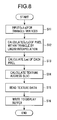
- FIG. 8 is a flow chart for explaining an operation of the texture mapping apparatus of FIG. 7 ;
- FIG. 9 is a block diagram showing an example of an lod calculating apparatus of FIG. 7 ;
- FIG. 10 is a schematic representation for explaining a method of calculating an lod in the lod calculating apparatus of FIG. 7 ;
- FIG. 11 is a graph showing the relationship between log 2 m and m
- FIG. 12 is a schematic representation for explaining a data structure of the lod
- FIG. 13 is a schematic representation for explaining a correspondence table
- FIG. 14 is a schematic representation for explaining a decimal fraction part
- FIG. 15 is a block diagram showing an example of a personal computer 501 .
- FIG. 7 shows an example of a texture mapping apparatus 1 to which the present invention is applied.
- the texture mapping apparatus 1 is provided with an lod calculating apparatus 101 in place of the lod calculating apparatus 2 of FIG. 4 .
- steps S 11 , S 12 , and step S 14 to step S 16 processes similar to steps S 1 , S 2 and step S 4 to step S 6 of FIG. 5 are carried out, and description thereof is omitted to avoid redundancy.
- step S 13 the lod calculating apparatus 101 performs an operation of equation (6) according to (s, t, q) of each pixel within the polygon so as to obtain an lod.
- Equation (6) is obtained in such a way that equation (5), which has been performed its operation so as to calculate the lod in the lod calculating apparatus 2 of FIG. 4 , is expanded or modified so as not to include a division. More specifically, equation (5) is expanded to obtain equation (7), and further expanded or modified to obtain equation (6).
- FIG. 9 shows an example of the lod calculating apparatus 101 .
- the lod calculating apparatus 2 of FIG. 4 is provided with 22 multipliers, the lod calculating apparatus 101 includes only 9 multipliers, thereby the apparatus is down-scaled.
- Each of circuits 111 A, 111 B, 111 I, and 111 J of FIG. 9 includes two multipliers, a subtracter, and an absolute value detector.
- the circuit 111 A including a multiplier 121 - 1 to an absolute value detector 121 - 4 performs an operation of a portion A of equation (6), and outputs its operational result to a maximum value detector 111 C.
- the multiplier 121 - 1 multiplies dS/dx by Q
- a multiplier 121 - 2 multiplies dQ/dx by S
- each multipliers outputs respective resulting product to a subtracter 121 - 3 .
- the subtracter 121 - 3 subtracts the resulting product of the multiplier 121 - 2 from the resulting product of the multiplier 121 - 1 in order to output its resulting subtraction to the absolute value detector 121 - 4 .
- the absolute value detector 121 - 4 detects an absolute value of the resulting subtraction of the subtracter 121 - 3 , and outputs its resulting detection to the maximum value detector 111 C.
- the circuit 111 B including a multiplier 122 - 1 to an absolute value detector 122 - 4 performs an operation of a portion B of equation (6), and outputs its operational result to a maximum value detector 111 C.
- the maximum value detector 111 C detects the greater of the operational result (a value of the portion A of equation (6)) from the circuit 111 A and the operational result (a value of the portion B of equation (6)) from the circuit 111 B in order to output the greater to a logarithmic operation unit 111 D. Specifically, the maximum value detector 111 C performs the operation of the portion C of equation (6).
- the logarithmic operation unit 111 D performs an operation of a logarithm, having a base of 2, of the value from the maximum value detector 111 C (performs an operation of a portion D of equation (6)), and outputs its operational result to an adder 131 .
- a logarithmic operation unit 111 E performs an operation of a logarithm, having a base of 2, of USIZE (performs an operation of a portion E of equation (6)), and outputs its operational result to a subtracter 132 .
- a multiplier 111 F performs an operation of square of Q (performs an operation of a portion F of equation (6)), and outputs its operational result to a logarithmic operation unit 111 G.
- the logarithmic operation unit 111 G performs an operation of a logarithm, having a base of 2, of the square of Q (performs an operation of a portion G), and outputs its operational result to the subtracter 132 and a subtracter 133 .
- a logarithmic operation unit 111 H performs an operation of a logarithm, having a base of 2, of VSIZE (performs an operation of a portion H of equation (6)), and outputs its operational result to the subtracter 133 .
- a circuit 111 I including a multiplier 123 - 1 to an absolute value detector 123 - 4 performs an operation of a portion I of equation (6)
- a circuit 111 J including a multiplier 124 - 1 to an absolute value detector 124 - 4 performs an operation of a portion J of equation (6).
- the circuits output respective operational results to a maximum value detector 111 K.
- the maximum value detector 111 K detects the greater of the operational result (a value of the portion I of equation (6)) from the circuit 111 I and the operational result (a value of the portion J of equation (6)) from the circuit 111 J (performs an operation of a portion K), and outputs the greater to a logarithmic operation unit 111 L.
- the logarithmic operation unit 111 L performs an operation of a logarithm, having a base of 2, of the value from the maximum value detector 111 K (performs an operation of a portion L), and outputs its operational result to an adder 134 .
- the subtracter 132 subtracts the result of the logarithmic operation unit 111 G from the result of the logarithmic operation unit 111 E, and outputs its resulting subtraction to the adder 131 .
- the adder 131 adds the result of the logarithmic operation unit 111 D to the result of the subtracter 132 , and outputs its resulting addition to a maximum value detector 135 .
- the subtracter 133 subtracts the result of the logarithmic operation unit 111 G from the result of the logarithmic operation unit 111 H, and outputs its resulting subtraction to the adder 134 .
- the adder 134 adds the result of the logarithmic operation unit 111 L to the result of the subtracter 133 , and outputs its resulting addition to the maximum value detector 135 .
- the maximum value detector 135 detects the greater of the operational result from the adder 131 and the result from the adder 134 , and outputs its resulting detection (operational result of the whole equation (6)) as an lod to the display buffer 4 .
- the logarithmic operation units 111 D, E, G, H, L perform operations of logarithm, having a base of 2, of inputted value (hereinafter referred to as value W) as shown in the equation of FIG. 10A . Since the value inputted to the lod calculating apparatus 101 is a numeric value with floating point, an operation of a logarithm of the numeric value with floating point is carried out.
- the value W in numeric value with floating point is represented as shown in FIG. 10B . If a logarithm of the value is taken, having a base of 2, as shown in the left side of FIG. 10C , the right side of FIG. 10C may be obtained.
- a trace of the second term (log 2 m) on the right side of FIG. 10C may be as shown in FIG. 11 .
- the second term on the right side of FIG. 10C may be approximated to a straight line passing through a point A and a point B in FIG. 11 so that the equation of FIG. 10D is valid.
- error(m) in the equation of FIG. 10D is a difference between the second term on the right side of FIG. 10C and the straight line passing the points A and B of FIG. 11 (difference between log 2 m and (m ⁇ 1.0)).
- a logarithmic operation unit obtains e and m which form a numeric value of floating point of the value W and error(m) corresponding to m.
- a value of the logarithm of FIG. 10A may be obtained.
- error(m) (as in equations of FIGS. 10D , 10 E, FIG. 11 ) provides one-to-one correspondence to m.
- the logarithmic operation unit stores a correspondence table (which will be described later and is in particular a correspondence table where m ⁇ 1 and error(m) are in one-to-one correspondence), and that the error(m) corresponding to m of the value W is obtained from the correspondence table.
- an addition of e, (m ⁇ 1.0) to error(m) (which is an operation of the right side of FIG. 10E ) is carried out in such a way that e is represented by 4 bits and set at an integral part, and (m ⁇ 1.0+error(m)) is represented by 4 bits and set at a decimal fraction part as shown in FIG. 12 because e is an integer and (m ⁇ 1.0)+error(m) becomes a value after the decimal point if 1 ⁇ m ⁇ 2.
- the lod consists of an integral part of 4 bits and a decimal fraction part of 4 bits.
- an addition of (m ⁇ 1.0) to error(m) is carried out by adding the 4 bits representing m ⁇ 1.0 to the 4 bits representing error(m).
- the 4 bits representing (m ⁇ 1.0) as a numeric value after the decimal point and the 4 bits corresponding thereto and representing error(m) as a numeric value after the decimal point are set in the correspondence table as shown in FIG. 13 .
- the 4 bits representing m ⁇ 1.0 is “1000”. Accordingly, the value “1000” is added to “0001” of the term error(m) which is set according to “1000” of the term m ⁇ 1.0 in the correspondence table, thereby “1001” of its resulting addition becomes a decimal fraction part.
- the value of 0.5 is represented in such a way that the value of 1 set at the 1 bit for representing the integer as in FIG. 14A is shifted to the right in FIGS. by 1 bit (or the value of 1 is reduced to half) so that the value of 0.5 is becomes a “1000” as shown in FIG. 14B .
- a series of processes as described above may be provided by means of hardware and software as well.
- one or more programs which compose the software are installed in a computer and executed in the computer, thereby functionalities of the lod calculating apparatus 101 described above are realized.
- FIG. 15 is a block diagram showing an embodiment of a computer 501 which functions as the lod calculating apparatus 101 as described above.
- a CPU (Central Processing Unit) 511 is connected to an input/output interface 516 via a bus 515 .
- an input unit 518 such as a keyboard, a mouse via the input/output interface 516
- the CPU 511 loads a program on a RAM (Random Access Memory) 513 so as to execute.
- RAM Random Access Memory
- the program may be stored in a storage medium such as ROM (Read Only Memory) 512 , a hard disk 514 , and a magnetic disk 531 , a optical disk 532 , a magneto-optical disk 533 and a semiconductor memory 534 which may be mounted in a drive 520 , thereby each process as described above is carried out.
- ROM Read Only Memory
- the CPU 511 outputs its result to an output unit 517 such as an LCD (Liquid Crystal Display) through the input/output interface 516 , for example.
- the program may be stored in the hard disk 514 or the ROM 512 beforehand so as to be provided together with the computer 501 , or may be provided as a package medium such as the magnetic disk 531 , the optical disk 532 , the magneto-optical disk 533 and the semiconductor memory 534 or may be provided to the hard disk 514 through a communication unit 519 by means of a satellite, a network or the like.
- the steps describing the program provided by means of a storage medium may be processes wherein the steps are carried out in a time-serial order as described above, or may be processes where the steps are performed in parallel or individually instead of the time serial order.
- a “system” is intended to refer to a whole group of apparatuses including a plurality of apparatuses.
Applications Claiming Priority (2)
| Application Number | Priority Date | Filing Date | Title |
|---|---|---|---|
| JP2001-355866 | 2001-11-21 | ||
| JP2001355866A JP3775580B2 (ja) | 2001-11-21 | 2001-11-21 | 画像処理装置および方法、記録媒体、並びにプログラム |
Publications (2)
| Publication Number | Publication Date |
|---|---|
| US20030117399A1 US20030117399A1 (en) | 2003-06-26 |
| US7151862B2 true US7151862B2 (en) | 2006-12-19 |
Family
ID=19167490
Family Applications (1)
| Application Number | Title | Priority Date | Filing Date |
|---|---|---|---|
| US10/299,297 Expired - Fee Related US7151862B2 (en) | 2001-11-21 | 2002-11-19 | Image processing apparatus and method, storage medium, and program |
Country Status (2)
| Country | Link |
|---|---|
| US (1) | US7151862B2 (ja) |
| JP (1) | JP3775580B2 (ja) |
Families Citing this family (4)
| Publication number | Priority date | Publication date | Assignee | Title |
|---|---|---|---|---|
| JP4140575B2 (ja) * | 2004-07-30 | 2008-08-27 | ソニー株式会社 | 画像変形装置,画像変形回路及び画像変形方法 |
| JP4462132B2 (ja) | 2005-07-04 | 2010-05-12 | ソニー株式会社 | 画像特殊効果装置,グラフィックスプロセッサ,プログラム |
| US8106918B2 (en) * | 2007-05-01 | 2012-01-31 | Vivante Corporation | Apparatus and method for texture level of detail computation |
| US8207980B2 (en) * | 2007-05-01 | 2012-06-26 | Vivante Corporation | Coordinate computations for non-power of 2 texture maps |
Citations (8)
| Publication number | Priority date | Publication date | Assignee | Title |
|---|---|---|---|---|
| US5436733A (en) * | 1991-05-14 | 1995-07-25 | Fuji Xerox Co. Ltd. | Image processing apparatus for combining image data and texture image data |
| US5767858A (en) * | 1994-12-01 | 1998-06-16 | International Business Machines Corporation | Computer graphics system with texture mapping |
| US6034786A (en) * | 1996-09-02 | 2000-03-07 | Samsung Electronics Co., Ltd. | Apparatus and method for enlarging or reducing an image in an image processing system |
| US6476818B1 (en) * | 1998-03-17 | 2002-11-05 | Sony Corporation | Storage circuit control device and graphic computation device |
| US6693634B1 (en) * | 1999-09-07 | 2004-02-17 | Sony Corporation | Reduction rate processing circuit and method with logarithmic operation and image processor employing same |
| US6744440B1 (en) * | 1999-09-10 | 2004-06-01 | Sony Computer Entertainment Inc. | Image processing apparatus, recording medium, and program |
| US6988059B1 (en) * | 1999-09-14 | 2006-01-17 | Kabushiki Kaisha Square Enix | Rendering method and device, game device, and computer-readable recording medium for storing program to render stereo model |
| US6992664B2 (en) * | 2000-02-29 | 2006-01-31 | Sony Corporation | Graphics plotting apparatus |
-
2001
- 2001-11-21 JP JP2001355866A patent/JP3775580B2/ja not_active Expired - Fee Related
-
2002
- 2002-11-19 US US10/299,297 patent/US7151862B2/en not_active Expired - Fee Related
Patent Citations (8)
| Publication number | Priority date | Publication date | Assignee | Title |
|---|---|---|---|---|
| US5436733A (en) * | 1991-05-14 | 1995-07-25 | Fuji Xerox Co. Ltd. | Image processing apparatus for combining image data and texture image data |
| US5767858A (en) * | 1994-12-01 | 1998-06-16 | International Business Machines Corporation | Computer graphics system with texture mapping |
| US6034786A (en) * | 1996-09-02 | 2000-03-07 | Samsung Electronics Co., Ltd. | Apparatus and method for enlarging or reducing an image in an image processing system |
| US6476818B1 (en) * | 1998-03-17 | 2002-11-05 | Sony Corporation | Storage circuit control device and graphic computation device |
| US6693634B1 (en) * | 1999-09-07 | 2004-02-17 | Sony Corporation | Reduction rate processing circuit and method with logarithmic operation and image processor employing same |
| US6744440B1 (en) * | 1999-09-10 | 2004-06-01 | Sony Computer Entertainment Inc. | Image processing apparatus, recording medium, and program |
| US6988059B1 (en) * | 1999-09-14 | 2006-01-17 | Kabushiki Kaisha Square Enix | Rendering method and device, game device, and computer-readable recording medium for storing program to render stereo model |
| US6992664B2 (en) * | 2000-02-29 | 2006-01-31 | Sony Corporation | Graphics plotting apparatus |
Also Published As
| Publication number | Publication date |
|---|---|
| US20030117399A1 (en) | 2003-06-26 |
| JP3775580B2 (ja) | 2006-05-17 |
| JP2003157445A (ja) | 2003-05-30 |
Similar Documents
| Publication | Publication Date | Title |
|---|---|---|
| US11830143B2 (en) | Tessellation method using recursive sub-division of triangles | |
| US7034823B2 (en) | 3D computer graphics processing apparatus and method | |
| US7239319B2 (en) | Rendering outline fonts | |
| JP3318914B2 (ja) | ベツィエスプラインをレンダリングするためのシステムおよび方法 | |
| US6323874B1 (en) | System and method for rendering an image | |
| US20110109625A1 (en) | Drawing processing apparatus, texture processing apparatus, and tessellation method | |
| EP0425177A2 (en) | Parametric surface evaluation for a computer graphics display system | |
| US5317682A (en) | Parametric curve evaluation method and apparatus for a computer graphics display system | |
| JPH06124314A (ja) | コンピュータ支援設計システムおよびそのシステムにおける幾何学的対象を修正する方法 | |
| JP2618951B2 (ja) | 三次元図形処理装置 | |
| US20140071124A1 (en) | Image processing apparatus | |
| KR100277803B1 (ko) | 3차원 그래픽 표시장치 | |
| CA2050651A1 (en) | Integrated hardware generator for area fill, conics and vectors in a graphics rendering processor | |
| JPH0927039A (ja) | オブジェクトにテクスチャを表示するためにテクセル値を計算する方法及び装置 | |
| JP2006520963A (ja) | 直接推定を用いた三角形レンダリング | |
| US7151862B2 (en) | Image processing apparatus and method, storage medium, and program | |
| US7015930B2 (en) | Method and apparatus for interpolating pixel parameters based on a plurality of vertex values | |
| US6850244B2 (en) | Apparatus and method for gradient mapping in a graphics processing system | |
| JP2926637B2 (ja) | ボリュームレンダリング装置及びこれに好適な方法 | |
| US6711603B1 (en) | Fractional, arithmetic unit, fractional arithmetic method, set-up engine for handling graphic images and computer-readable medium | |
| US7015917B2 (en) | Curved surface subdivision apparatus | |
| US6940520B2 (en) | Anisotropic texture filtering method and apparatus using area coverage weight of sub-texel precision | |
| US8274513B1 (en) | System, method, and computer program product for obtaining a boundary attribute value from a polygon mesh, during voxelization | |
| US6460063B1 (en) | Division circuit and graphic display processing apparatus | |
| US7301540B1 (en) | System and method for rasterization through approximation |
Legal Events
| Date | Code | Title | Description |
|---|---|---|---|
| AS | Assignment |
Owner name: SONY CORPORATION, JAPAN Free format text: ASSIGNMENT OF ASSIGNORS INTEREST;ASSIGNORS:NAGASAKI, TANIO;TOMIKAWA, HIDEAKI;IWASAKI, SEIGO;AND OTHERS;REEL/FRAME:013781/0493;SIGNING DATES FROM 20030109 TO 20030124 |
|
| FEPP | Fee payment procedure |
Free format text: PAYER NUMBER DE-ASSIGNED (ORIGINAL EVENT CODE: RMPN); ENTITY STATUS OF PATENT OWNER: LARGE ENTITY Free format text: PAYOR NUMBER ASSIGNED (ORIGINAL EVENT CODE: ASPN); ENTITY STATUS OF PATENT OWNER: LARGE ENTITY |
|
| FPAY | Fee payment |
Year of fee payment: 4 |
|
| REMI | Maintenance fee reminder mailed | ||
| LAPS | Lapse for failure to pay maintenance fees | ||
| STCH | Information on status: patent discontinuation |
Free format text: PATENT EXPIRED DUE TO NONPAYMENT OF MAINTENANCE FEES UNDER 37 CFR 1.362 |
|
| FP | Lapsed due to failure to pay maintenance fee |
Effective date: 20141219 |