US7134473B2 - Anti-bow roller tube arrangement - Google Patents
Anti-bow roller tube arrangement Download PDFInfo
- Publication number
- US7134473B2 US7134473B2 US10/943,302 US94330204A US7134473B2 US 7134473 B2 US7134473 B2 US 7134473B2 US 94330204 A US94330204 A US 94330204A US 7134473 B2 US7134473 B2 US 7134473B2
- Authority
- US
- United States
- Prior art keywords
- roller tube
- support
- mount
- sheet material
- assembly
- Prior art date
- Legal status (The legal status is an assumption and is not a legal conclusion. Google has not performed a legal analysis and makes no representation as to the accuracy of the status listed.)
- Active - Reinstated, expires
Links
Images


Classifications
-
- G—PHYSICS
- G03—PHOTOGRAPHY; CINEMATOGRAPHY; ANALOGOUS TECHNIQUES USING WAVES OTHER THAN OPTICAL WAVES; ELECTROGRAPHY; HOLOGRAPHY
- G03B—APPARATUS OR ARRANGEMENTS FOR TAKING PHOTOGRAPHS OR FOR PROJECTING OR VIEWING THEM; APPARATUS OR ARRANGEMENTS EMPLOYING ANALOGOUS TECHNIQUES USING WAVES OTHER THAN OPTICAL WAVES; ACCESSORIES THEREFOR
- G03B21/00—Projectors or projection-type viewers; Accessories therefor
- G03B21/54—Accessories
- G03B21/56—Projection screens
- G03B21/58—Projection screens collapsible, e.g. foldable; of variable area
-
- E—FIXED CONSTRUCTIONS
- E06—DOORS, WINDOWS, SHUTTERS, OR ROLLER BLINDS IN GENERAL; LADDERS
- E06B—FIXED OR MOVABLE CLOSURES FOR OPENINGS IN BUILDINGS, VEHICLES, FENCES OR LIKE ENCLOSURES IN GENERAL, e.g. DOORS, WINDOWS, BLINDS, GATES
- E06B9/00—Screening or protective devices for wall or similar openings, with or without operating or securing mechanisms; Closures of similar construction
- E06B9/24—Screens or other constructions affording protection against light, especially against sunshine; Similar screens for privacy or appearance; Slat blinds
- E06B9/40—Roller blinds
- E06B9/42—Parts or details of roller blinds, e.g. suspension devices, blind boxes
- E06B9/50—Bearings specially adapted therefor
-
- E—FIXED CONSTRUCTIONS
- E04—BUILDING
- E04F—FINISHING WORK ON BUILDINGS, e.g. STAIRS, FLOORS
- E04F10/00—Sunshades, e.g. Florentine blinds or jalousies; Outside screens; Awnings or baldachins
- E04F10/02—Sunshades, e.g. Florentine blinds or jalousies; Outside screens; Awnings or baldachins of flexible canopy materials, e.g. canvas ; Baldachins
- E04F10/06—Sunshades, e.g. Florentine blinds or jalousies; Outside screens; Awnings or baldachins of flexible canopy materials, e.g. canvas ; Baldachins comprising a roller-blind with means for holding the end away from a building
- E04F10/0666—Accessories
- E04F10/0677—Accessories acting as centre bearing
-
- Y—GENERAL TAGGING OF NEW TECHNOLOGICAL DEVELOPMENTS; GENERAL TAGGING OF CROSS-SECTIONAL TECHNOLOGIES SPANNING OVER SEVERAL SECTIONS OF THE IPC; TECHNICAL SUBJECTS COVERED BY FORMER USPC CROSS-REFERENCE ART COLLECTIONS [XRACs] AND DIGESTS
- Y10—TECHNICAL SUBJECTS COVERED BY FORMER USPC
- Y10S—TECHNICAL SUBJECTS COVERED BY FORMER USPC CROSS-REFERENCE ART COLLECTIONS [XRACs] AND DIGESTS
- Y10S160/00—Flexible or portable closure, partition, or panel
- Y10S160/903—Roll type bracket means
Definitions
- the present invention relates to solar screens and awnings, and more particularly, to a roller tube and assembly for a solar screen or awning including an integral support cradle.
- roller shade systems make use of flexible shades supported by elongated roller tubes.
- the roller tube typically made from aluminum or steel, is rotatably supported and provides support for the flexible shade on the roller tube.
- Roller shades include manual shades having spring driven roller tubes and motorized shades having drive motors engaging the roller tube to rotatingly drive the tube.
- the drive motors for motorized shades include externally mounted motors engaging an end of the roller tube and internal motors that are received within an interior defined by the tube.
- roller shades have support systems that engage the opposite ends of the roller tube to provide the rotatable support that is required for winding and unwinding of the flexible shade.
- the support system includes a drive end support assembly having a coupler engaging the open end of the tube for rotation.
- the coupler is adapted to receive the drive shaft of a motor such that rotation of the drive shaft is transferred to the coupler for rotation of the tube.
- the motor is secured to a bracket for attachment of the roller shade system to the wall or ceiling of a structure, for example.
- a coupler engaging an opposite end of the roller tube could receive a motor drive shaft or, alternatively, could receive a rotatably supported shaft of an idler assembly.
- a roller shade tube supported in a conventional manner from the opposite ends will deflect in response to transverse loading, from the weight of an attached shade for example.
- the response of a roller tube, supported at its ends in a conventional manner, from the weight of a flexible shade as well as from self-weight of the tube, results in a downward “sagging” deflection in a central portion of the roller tube with respect to the supported ends.
- V-shaped wrinkles also known as “smiles”
- Sagging deflection in a conventionally supported roller tube can also have a detrimental effect on shade operation.
- the shade is drawn onto the tube in a direction that is substantially perpendicular to the axis of the tube.
- roller tube diameter serves to reduce sagging deflection in conventional end-supported tubes, there are undesirable consequences associated with such a solution.
- Increasing the diameter of the roller tube increases weight, thereby potentially affecting the size and type of structure capable of providing rotatable support for the tube.
- additional space required by the larger diameter roller tube and its associated support structure may not be readily available in many installations. Even if space is available, the bulky nature of the system due to the required large roller tube diameter is often objectionable for aesthetic reasons.
- roller tube support mechanism having a fixed support cradle.
- a support mechanism comprises a roller tube including a body.
- the roller tube is configured to support a sheet material wound around the roller tube body along a length of the body between a first end and a second end of the body.
- An assembly includes a first mount and a second mount opposite the first mount. The assembly is configured to support the roller tube rotatably coupled to the first mount and the second mount.
- a support cradle is coupled to the assembly between the first mount and the second mount. The support cradle is configured to support the roller tube along the length of the roller tube.
- the body can have a cylindrical shape.
- the sheet material can be one of a screen and fabric configured to shade sunlight.
- the assembly can be configured to releasably contain the roller tube and sheet material thereon and discharge the sheet material proximate the support cradle.
- the first mount and second mount can be configured provide both rotary support and translational support to the roller tube.
- Each of the first and second mounts can include at least one slot formed in the assembly at each of the first and second ends respectively.
- the configuration can include a central slot bounded by two opposing side slots, wherein the central slot is configured to support an idler and the opposing side slots can be configured to support at least one of a motor and a drive gear.
- the slot can be configured to guide and support the roller tube responsive to a variable diameter of the roller tube and sheet material.
- the first and second mounts each can include a slotted insert configured to couple to the first and second ends of the assembly.
- the slotted insert can include an idler groove between a pair of side grooves.
- the pair of side grooves can be configured to support at least one of a motor bearing and a drive gear bearing.
- the slotted insert can be concealable in an interior of the assembly.
- Each of the first and second mounts can include a pivot arm assembly configured to support the roller tube.
- the pivot arm assembly can be pivotably coupled to the assembly proximate the first mount and the second mount respectfully and concealable in the interior of the assembly.
- the pivot arm assembly can include an idler receiver and a set of opposing receivers adjacent the idler receiver.
- the pivot arm assembly can be configured to guide and support the roller tube responsive to a variable diameter of the roller tube and sheet material.
- the support cradle can be fixed with respect to the assembly and the roller tube.
- the support cradle can be crescent shaped.
- the support cradle can contact the sheet material proximate a lower portion of the roller tube.
- the support cradle can be formed integral with the assembly.
- the support cradle can support the roller tube and sheet material below an axis of rotation of the roller tube.
- the support cradle can support the roller tube body substantially along the entire length of the tube body.
- the support cradle can continuously support the roller tube body and the sheet material along the length responsive to variation of a diameter of the sheet material wound around the roller tube body resulting from winding and unwinding the sheet material around the roller tube body.
- An exemplary method of supporting a roller tube is provided.
- the method provides for disposing a sheet material on the roller tube.
- the roller tube includes a body having a first end and a second end.
- the sheet material can be wound around the roller tube body along a length of the body between the first end and the second end.
- the roller tube can be mounted in an assembly.
- the assembly can include a first mount and a second mount opposite thereof.
- the roller tube can be supported on the first and second mounts wherein the roller tube is rotatable for winding and unwinding the sheet material on the roller tube.
- the method includes supporting the roller tube along the length on a support cradle coupled to the assembly.
- the support cradle can be integrally fixed to the assembly.
- the invention provides for supporting the roller tube at each of the first and second mounts in both a rotary motion and a translational motion responsive to a variable diameter of the sheet material on the roller tube.
- the first and second mounts comprise one of a slot formed in the assembly and a slotted insert mounted in an interior of the assembly and a pivot arm assembly mounted in the interior.
- the method provides for concealing the first and second mounts in an interior of the assembly.
- the roller tube can be prevented from deflection along the length by the cradle support. Surface discontinuities can be prevented along a surface of the sheet material responsive to unwinding the sheet material across the cradle support.
- FIG. 1 is a perspective view of an exemplary roller tube support mechanism.
- FIG. 2 is a side view of an exemplary roller tube support mechanism.
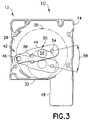
- FIG. 3 is a side view of an exemplary roller tube support mechanism.
- FIG. 4 is a perspective view of an exemplary mount.
- FIG. 5 is a perspective view of another exemplary mount.
- FIG. 6 is a perspective view of another exemplary mount.
- the disclosure provides an exemplary roller tube support mechanism.
- the roller tube support mechanism can include an assembly including a first mount and a second mount opposite each other.
- the assembly can be configured to support a roller tube rotatably coupled to the first mount and the second mount.
- the roller tube includes a body defining a length between a first end and a second end.
- the roller tube can be configured to support a sheet material wound around the roller tube body along the length of the body between the first and second ends of the body.
- a support cradle can be coupled to the assembly between the first and second mounts.
- the support cradle can be configured to support the roller tube along the length of the roller tube.
- the sheet material can comprise one of a solar screen or awning material for an awning, such as lateral arm awnings or retractable window awnings.
- FIGS. 1 and 2 illustrate exemplary embodiments of the roller tube mechanism 10 .
- the roller tube mechanism 10 includes a assembly 12 that extends laterally between a first mount 14 and a second mount 16 opposite the first mount 14 .
- the assembly 12 can be mounted on a wall, ceiling, or the like, to provide a stable position to deploy a sheet material 18 .
- the assembly 12 can be constructed of a rigid material through various means including, for example, extruded aluminum, and the like.
- a roller tube 20 is rotatably mounted in the assembly 12 .
- the roller tube 20 can be pivotably supported on the first mount 14 and second mount 16 .
- the roller tube 20 includes a body 22 that extends along a length 24 between a first end 26 and a second end 28 .
- the roller tube body 22 can have a cylindrical shape including a circular cross-section extending along the length 24 .
- the roller tube 20 is configured to support the sheet material 18 , such as solar screen material.
- the sheet material 18 can be wound around the roller tube 20 about an axis of rotation (axis) 30 of the roller tube 20 . As the sheet material 18 is wound (wrapped) around the roller tube body 22 , the diameter of the roller tube 20 and sheet material 18 increases. As the sheet material is unwound, the diameter of the roller tube 20 and sheet material 18 decreases.
- a support cradle 32 is coupled to the assembly 12 .
- the support cradle 32 extends between the first mount 14 and the second mount 16 .
- the support cradle 32 is configured to support the roller tube 20 and sheet material 18 wound thereon. More specifically, the support cradle 32 supports the roller tube 20 along the entire length 24 of the roller tube 20 .
- the roller tube 20 is prevented from bowing along the length 24 due to the support from the support cradle 32 .
- the support cradle 32 can comprise a portion of the assembly 12 .
- the support cradle 32 can be formed separate from the assembly 12 and coupled to the assembly 12 .
- the support cradle 32 is positioned such that the roller tube 20 and sheet material 18 rest on top of the support cradle 32 .
- the support cradle 32 can be positioned such that an upper surface 36 contacts the sheet material near a lower portion of the roller tube 20 below the axis 30 .
- the support cradle 32 can support the roller tube 20 and sheet material 18 throughout the winding and unwinding of the sheet material 18 during which the outer diameter of the sheet material 18 on the roller tube 20 varies.
- the support cradle 32 comprises a base 34 including the upper surface 36 and a lower surface 38 .
- the base 34 can be formed into an elongate arcuate beam cupped to support the arcuate shape of the outer diameter of the roller 20 and sheet material 18 wrapped on the roller 20 .
- the base 34 can include a width that extends outward a distance sufficient to support the roller 20 without snagging or binding to roller 20 .
- the base 34 can include a width approximately the size of a quarter of the outer perimeter of the roller 20 and sheet material 18 thereon.
- a coupling arm 40 can extend from the lower surface 38 and couple to the assembly 12 .
- the base 34 can have a crescent shaped cross-section.
- the base 34 can be a circular cross-section, or the like.
- the shape of the support cradle 32 can substantially mate to the shape of the roller tube 20 and sheet material 18 .
- the upper surface can include a coating (not shown) that enables the sheet material 18 to slide across the support cradle upper surface 36 without sticking, being marked, or discolored.
- the upper surface 36 is coated (e.g., painted) to prevent the surfaces of the sheet material 18 from being marked (e.g., by aluminum oxide) as the material 18 unwinds.
- the support cradle 32 can be manufactured using a material such as high-density polyurethane, PVC, or the like.
- the support cradle 32 is rigid and does not move relative to the roller tube 20 , sheet material 18 or assembly 12 .
- the support cradle 32 can extend the entire length 24 of the roller tube 20 in a preferred embodiment. It is also contemplated that the support cradle 32 can extend substantially the length 24 of the roller tube 20 and variations thereof.
- the support cradle 32 can be integrally formed from the assembly 12 .
- the support cradle 32 can extend in a single contiguous length.
- the support cradle 32 can include segmentation and discontinuities along the length and/or the width of the base 34 .
- the support cradle 32 prevents the roller tube 20 from deflecting along the length 24 and resultantly prevents surface discontinuities from forming in the sheet material 18 as the sheet material 18 is dispensed out of the assembly 12 .
- an exemplary roller tube mechanism 10 is illustrated from a side view.
- the roller tube 20 is supported on both ends 26 and 28 , by the first mount 14 and second mount 16 .
- the first and second mounts 14 , 16 include a configuration for receiving bearings and drive mechanisms of the roller tube 20 .
- the mounts 14 , 16 comprise a pivot arm assembly 42 .
- the pivot arm assembly 42 includes a body 44 having a pivot mount 46 coupled to a cover plate 48 .
- the body 44 includes at least one bearing mount 50 , and in a preferred exemplary embodiment, a central bearing receiver 52 bounded by opposing receivers 54 , 56 .
- the central bearing receiver 52 can receive an idler of the roller tube 20 and the opposing receivers 54 , 56 can receive at least one of a drive motor and drive gears (not shown) or a pull chain and clutch mechanism (tape drive or chain drive) for the roller tube 20 .
- the drive motor can be mounted inside the roller tube for a compact arrangement.
- the appropriate gearing and drive mechanism can be coupled to the drive motor as is known in the art.
- the pivot arm assembly 42 illustrated in FIG. 3 is shown with a ghost image of the pivot arm assembly 42 to indicate the range of motion and capacity to pivot up and down with the roller tube 20 .
- the pivot arm assembly 42 can swing about pivot mount 46 through an angle 58 .
- the angle 58 can include a range from about zero degrees to about 45 degrees depending on the roller tube 20 size and expected service.
- the first and second mounts 14 , 16 are configured to support the roller tube 20 throughout the range of travel within the assembly 12 . As the sheet material 18 winds and unwinds on the roller tube 20 , the outside diameter of the roller tube 20 and material 18 wrapped thereon changes.
- the roller tube axis 30 moves relative to the cover plate 48 and fixed support cradle 32 (i.e., rotation and translation).
- the receivers 52 , 54 , 56 should also move with the roller tube 20 and accompanying drive motor, gears and idlers associated with the roller tube 20 .
- the exemplary embodiment of the pivot arm assembly 42 provides both the rotary support as well as the lateral support for the roller tube 20 while maintaining the roller tube 20 supported by the fixed support cradle 32 . It is noted that the pivot mount 46 may be slightly elongated to maintain the roller tube 20 centered over the support cradle 36 .
- FIGS. 4 through 6 are side views of exemplary mounts 14 , 16 .
- FIG. 4 illustrates the pivot arm assembly 42 , similar to the embodiment illustrated in FIG. 3 .
- the pivot arm assembly 42 embodiment allows the roller tube 20 to be supported while concealing the mechanism. A superior appearance can be gained through concealing the pivot arm assembly 42 inside the assembly 12 .
- Another embodiment is concealed behind the cover plate 48 of the mounts 14 and 16 as shown in FIG. 5 .
- a slotted insert 60 is attachable to the cover plate 48 of the mount 14 , 16 .
- the slotted insert 60 serves the same function as the pivot arm assembly 42 , of supporting the roller tube 20 in both translation and rotation.
- the slotted insert 60 includes an idler groove 62 formed between a pair of side grooves 64 , 66 .
- the idler groove 62 and side grooves 64 , 66 can be formed as raised flanges 68 extending from a base 70 .
- the idler groove 62 and side grooves 64 , 66 can be machined into the base 70 , cast in the base 70 , attached to the base 70 , and the like.
- the centrally located idler groove 62 can receive a bushing or bearing axle of an idler (see FIG.
- the side grooves 64 , 66 can receive a bushing or bearing or axle of a drive motor and/or gears (see FIG. 6 ) of the roller tube 20 .
- the slotted insert 60 is also concealed behind the cover plate 48 and provides an aesthetic quality to the assembly 12 .
- a less elaborate embodiment can include slots formed in the cover plate 48 , as shown in FIG. 6 .
- the embodiment of FIG. 6 includes at least one slot 72 formed in the cover plate 48 of the mount 14 , 16 .
- a central slot 74 and opposing side slots 76 , 78 can be formed in the mounts 14 , 16 to support the roller tube in both rotation and translation.
- the less complex embodiment of the slots 74 , 76 , 78 reduces manufacturing with an aesthetic tradeoff, since the ends of the bearings, axles and bushings, shown generally as 80 , are visible from the exterior of the assembly 12 .
- the exemplary roller tube support mechanism disclosed herein provides the advantage of supporting the roller tube without the need for complex moving parts.
- the roller tube and sheet material wrapped around the roller tube can be supported along the entire length.
- the problem of bowing and sagging across the roller tube and the resultant smile-shaped surface discontinuities on the sheet material are prevented as a result of the novel support mechanism.
- Further advantages of the disclosed roller tube support mechanism include the support cradle and assembly being formed integral improving strength, lowering weight and manufacturing costs.
- the novel assembly and support cradle allow for a variety of mounts to be employed in mounting the roller tube in the assembly.
- a reduced diameter roller tube can be used, since the sheet material and roller tube are supported over the length of the roller tube, enabling a solar screen system to significantly reduce the size required to house the roller tube, as compared to prior art systems.
- a solar screen housing provided by the present invention may be only about 3 inches by 3 inches in cross-section for a given size solar screen, whereas the prior art devices require larger diameter roller tubes for the same size solar screen and are typically 8 inches by 8 inches or greater in cross-section.
Abstract
Description
Claims (19)
Priority Applications (11)
| Application Number | Priority Date | Filing Date | Title |
|---|---|---|---|
| US10/943,302 US7134473B2 (en) | 2004-09-17 | 2004-09-17 | Anti-bow roller tube arrangement |
| US11/086,819 US7770625B2 (en) | 2004-09-17 | 2005-03-22 | Anti-bow roller tube arrangement |
| CA2509274A CA2509274C (en) | 2004-09-17 | 2005-06-07 | Anti-bow roller tube arrangement |
| EP05012282A EP1637668B1 (en) | 2004-09-17 | 2005-06-08 | Anti-bow roller tube arrangement |
| JP2005175525A JP2006083684A (en) | 2004-09-17 | 2005-06-15 | Deformation preventive roller tube structure |
| BRPI0502527-3A BRPI0502527A (en) | 2004-09-17 | 2005-06-16 | anti-winding winding tube arrangement |
| MXPA05007027A MXPA05007027A (en) | 2004-09-17 | 2005-06-27 | Anti-bow roller tube arrangement. |
| CNA2005100853397A CN1749142A (en) | 2004-09-17 | 2005-07-22 | Anti-bow roller tube arrangement |
| AU2005287216A AU2005287216B2 (en) | 2004-09-17 | 2005-09-12 | Anti-bow roller tube arrangement |
| PCT/US2005/032558 WO2006033892A1 (en) | 2004-09-17 | 2005-09-12 | Anti-bow roller tube arrangement |
| US12/152,836 US8220520B2 (en) | 2004-09-17 | 2008-05-15 | Spring biased slide arrangement for anti-bow roller tube |
Applications Claiming Priority (1)
| Application Number | Priority Date | Filing Date | Title |
|---|---|---|---|
| US10/943,302 US7134473B2 (en) | 2004-09-17 | 2004-09-17 | Anti-bow roller tube arrangement |
Related Child Applications (1)
| Application Number | Title | Priority Date | Filing Date |
|---|---|---|---|
| US11/086,819 Continuation-In-Part US7770625B2 (en) | 2004-09-17 | 2005-03-22 | Anti-bow roller tube arrangement |
Publications (2)
| Publication Number | Publication Date |
|---|---|
| US20060060312A1 US20060060312A1 (en) | 2006-03-23 |
| US7134473B2 true US7134473B2 (en) | 2006-11-14 |
Family
ID=36072688
Family Applications (1)
| Application Number | Title | Priority Date | Filing Date |
|---|---|---|---|
| US10/943,302 Active - Reinstated 2024-09-30 US7134473B2 (en) | 2004-09-17 | 2004-09-17 | Anti-bow roller tube arrangement |
Country Status (2)
| Country | Link |
|---|---|
| US (1) | US7134473B2 (en) |
| CN (1) | CN1749142A (en) |
Cited By (19)
| Publication number | Priority date | Publication date | Assignee | Title |
|---|---|---|---|---|
| US20050077017A1 (en) * | 2003-09-03 | 2005-04-14 | Ramsey Robert M. | Release device and method of manufacturing, installing and operating the same |
| US20050205216A1 (en) * | 2004-03-17 | 2005-09-22 | Vrielink Gerrit J | Method and apparatus for installing window coverings |
| US20060060306A1 (en) * | 2004-09-17 | 2006-03-23 | Stephen Lukos | Anti-bow roller tube housing assembly |
| US20060060313A1 (en) * | 2004-09-17 | 2006-03-23 | Stephen Lukos | Anti-bow roller tube arrangement |
| US20060289120A1 (en) * | 2005-06-25 | 2006-12-28 | Thyssen Polymer Gmbh | Roller shutter box |
| US20070240443A1 (en) * | 2004-02-20 | 2007-10-18 | Oliver Merker | Refrigerated Cabinet with Rolling Night Blind |
| US20080135191A1 (en) * | 2006-12-06 | 2008-06-12 | Zakowski Joseph W | Link system for shade couplings |
| US20080289775A1 (en) * | 2004-09-17 | 2008-11-27 | Stephen Lukos | Spring biased slide arrangement for anti-bow roller tube |
| US20100071859A1 (en) * | 2007-02-07 | 2010-03-25 | Dynaco International S.A. | Device With a Shutter Which May Be Wound Around a Drum |
| US20100116443A1 (en) * | 2008-11-07 | 2010-05-13 | Mechoshade Systems, Inc. | Through shade system and method |
| US20100326605A1 (en) * | 2008-02-11 | 2010-12-30 | Francisco Guillen Chico | End cap for blind with entry guide |
| US20110132556A1 (en) * | 2009-12-07 | 2011-06-09 | Yu-Ting Kao | Curtain frame |
| US20170058600A1 (en) * | 2015-08-31 | 2017-03-02 | Sun Glow Window Covering Products of Canada Ltd. | Roller Shade System |
| US20170208980A1 (en) * | 2016-01-25 | 2017-07-27 | Current Products Corp. | Valance System For Window Coverings |
| US10309153B2 (en) | 2016-09-26 | 2019-06-04 | Draper, Inc. | Support system for rolled material |
| US10684542B2 (en) | 2017-05-16 | 2020-06-16 | Draper, Inc. | Projection screen system |
| US10895106B2 (en) | 2017-05-23 | 2021-01-19 | Hunter Douglas Inc. | Bottom rail assembly for a covering with adjustable roller position and related methods |
| US11314159B2 (en) * | 2020-06-08 | 2022-04-26 | Draper, Inc. | Projection screen system and method for mounting the same |
| US20230019557A1 (en) * | 2021-07-15 | 2023-01-19 | Three Smith Group Limited | Barrier member |
Families Citing this family (3)
| Publication number | Priority date | Publication date | Assignee | Title |
|---|---|---|---|---|
| CN103910162A (en) * | 2012-12-29 | 2014-07-09 | 上海沃迪自动化装备股份有限公司 | Shaft seat type square roller vibration shaping conveyor |
| JP7002250B2 (en) * | 2017-08-30 | 2022-01-20 | 立川ブラインド工業株式会社 | Roll screen |
| CN114314204A (en) * | 2020-09-30 | 2022-04-12 | 张家港宝视特影视器材有限公司 | Tensioning type anti-wrinkle curtain winding box |
Citations (21)
| Publication number | Priority date | Publication date | Assignee | Title |
|---|---|---|---|---|
| US477512A (en) | 1892-06-21 | Awning | ||
| US1595234A (en) * | 1925-12-02 | 1926-08-10 | Peter H Kuyper | Mounting for rolling screen construction |
| US1615830A (en) * | 1923-11-26 | 1927-02-01 | Derus John | Awning-roller center support |
| US1671545A (en) * | 1926-08-02 | 1928-05-29 | Reuther John | Rolling-screen bracket |
| US1742549A (en) | 1927-12-30 | 1930-01-07 | Andrew Dutton Company | Curtain-roll cradle |
| US1812416A (en) * | 1928-12-17 | 1931-06-30 | John A Smith | Awning support and protector |
| US1825198A (en) * | 1930-04-30 | 1931-09-29 | Negrini Bruno | Truck and guide member for roller blinds |
| US2248414A (en) * | 1938-12-28 | 1941-07-08 | Fanner Mfg Co | Awning center support |
| US2326642A (en) * | 1941-11-24 | 1943-08-10 | Astrup Company | Awning belt center support |
| US2894578A (en) | 1955-05-06 | 1959-07-14 | Orville S Caesar | Roller shade |
| US3421568A (en) | 1966-06-29 | 1969-01-14 | Wilbur R Youngs | Flexible door closure |
| US3882921A (en) * | 1972-08-04 | 1975-05-13 | Beauty Blinds Ltd | Roller screen assembly for an aperture |
| US3900063A (en) | 1973-06-18 | 1975-08-19 | J H Channon Inc | Roller curtain |
| US4347886A (en) * | 1980-05-30 | 1982-09-07 | Von Knorring Enar S | Roller blinds |
| US5121782A (en) * | 1990-01-29 | 1992-06-16 | Warema Renkhoff Gmbh & Co. Kg | Protective covering for a marquee on an articulated arm |
| US5423506A (en) | 1993-05-24 | 1995-06-13 | Recreation Vehicle Products, Inc. | Recreational vehicle awning support |
| EP0745742A2 (en) | 1995-06-01 | 1996-12-04 | WEINOR Dieter Weiermann GmbH & Co. | Awning |
| EP0792978A1 (en) | 1996-03-01 | 1997-09-03 | Schmitz-Werke GmbH & Co. | Awning, especially boxe awning |
| US5819831A (en) * | 1995-12-22 | 1998-10-13 | Schanz; Hans | Roller blind drive, more particularly for shade producing means |
| EP1030003A2 (en) | 1999-02-18 | 2000-08-23 | Helge Weiss | Awning with articulated arms |
| US20040129850A1 (en) | 2003-01-06 | 2004-07-08 | Kirby David A. | Roller shade mounting system |
Family Cites Families (1)
| Publication number | Priority date | Publication date | Assignee | Title |
|---|---|---|---|---|
| US447512A (en) * | 1891-03-03 | Vehicle-brake |
-
2004
- 2004-09-17 US US10/943,302 patent/US7134473B2/en active Active - Reinstated
-
2005
- 2005-07-22 CN CNA2005100853397A patent/CN1749142A/en active Pending
Patent Citations (21)
| Publication number | Priority date | Publication date | Assignee | Title |
|---|---|---|---|---|
| US477512A (en) | 1892-06-21 | Awning | ||
| US1615830A (en) * | 1923-11-26 | 1927-02-01 | Derus John | Awning-roller center support |
| US1595234A (en) * | 1925-12-02 | 1926-08-10 | Peter H Kuyper | Mounting for rolling screen construction |
| US1671545A (en) * | 1926-08-02 | 1928-05-29 | Reuther John | Rolling-screen bracket |
| US1742549A (en) | 1927-12-30 | 1930-01-07 | Andrew Dutton Company | Curtain-roll cradle |
| US1812416A (en) * | 1928-12-17 | 1931-06-30 | John A Smith | Awning support and protector |
| US1825198A (en) * | 1930-04-30 | 1931-09-29 | Negrini Bruno | Truck and guide member for roller blinds |
| US2248414A (en) * | 1938-12-28 | 1941-07-08 | Fanner Mfg Co | Awning center support |
| US2326642A (en) * | 1941-11-24 | 1943-08-10 | Astrup Company | Awning belt center support |
| US2894578A (en) | 1955-05-06 | 1959-07-14 | Orville S Caesar | Roller shade |
| US3421568A (en) | 1966-06-29 | 1969-01-14 | Wilbur R Youngs | Flexible door closure |
| US3882921A (en) * | 1972-08-04 | 1975-05-13 | Beauty Blinds Ltd | Roller screen assembly for an aperture |
| US3900063A (en) | 1973-06-18 | 1975-08-19 | J H Channon Inc | Roller curtain |
| US4347886A (en) * | 1980-05-30 | 1982-09-07 | Von Knorring Enar S | Roller blinds |
| US5121782A (en) * | 1990-01-29 | 1992-06-16 | Warema Renkhoff Gmbh & Co. Kg | Protective covering for a marquee on an articulated arm |
| US5423506A (en) | 1993-05-24 | 1995-06-13 | Recreation Vehicle Products, Inc. | Recreational vehicle awning support |
| EP0745742A2 (en) | 1995-06-01 | 1996-12-04 | WEINOR Dieter Weiermann GmbH & Co. | Awning |
| US5819831A (en) * | 1995-12-22 | 1998-10-13 | Schanz; Hans | Roller blind drive, more particularly for shade producing means |
| EP0792978A1 (en) | 1996-03-01 | 1997-09-03 | Schmitz-Werke GmbH & Co. | Awning, especially boxe awning |
| EP1030003A2 (en) | 1999-02-18 | 2000-08-23 | Helge Weiss | Awning with articulated arms |
| US20040129850A1 (en) | 2003-01-06 | 2004-07-08 | Kirby David A. | Roller shade mounting system |
Cited By (27)
| Publication number | Priority date | Publication date | Assignee | Title |
|---|---|---|---|---|
| US20050077017A1 (en) * | 2003-09-03 | 2005-04-14 | Ramsey Robert M. | Release device and method of manufacturing, installing and operating the same |
| US20070240443A1 (en) * | 2004-02-20 | 2007-10-18 | Oliver Merker | Refrigerated Cabinet with Rolling Night Blind |
| US20050205216A1 (en) * | 2004-03-17 | 2005-09-22 | Vrielink Gerrit J | Method and apparatus for installing window coverings |
| US20060060306A1 (en) * | 2004-09-17 | 2006-03-23 | Stephen Lukos | Anti-bow roller tube housing assembly |
| US20060060313A1 (en) * | 2004-09-17 | 2006-03-23 | Stephen Lukos | Anti-bow roller tube arrangement |
| US7441582B2 (en) * | 2004-09-17 | 2008-10-28 | Stephen Lukos | Anti-bow roller tube housing assembly |
| US20080289775A1 (en) * | 2004-09-17 | 2008-11-27 | Stephen Lukos | Spring biased slide arrangement for anti-bow roller tube |
| US8220520B2 (en) | 2004-09-17 | 2012-07-17 | Stephen Lukos | Spring biased slide arrangement for anti-bow roller tube |
| US7770625B2 (en) * | 2004-09-17 | 2010-08-10 | Stephen Lukos | Anti-bow roller tube arrangement |
| US20060289120A1 (en) * | 2005-06-25 | 2006-12-28 | Thyssen Polymer Gmbh | Roller shutter box |
| US20080135191A1 (en) * | 2006-12-06 | 2008-06-12 | Zakowski Joseph W | Link system for shade couplings |
| US20100071859A1 (en) * | 2007-02-07 | 2010-03-25 | Dynaco International S.A. | Device With a Shutter Which May Be Wound Around a Drum |
| US20100326605A1 (en) * | 2008-02-11 | 2010-12-30 | Francisco Guillen Chico | End cap for blind with entry guide |
| US8016016B2 (en) | 2008-11-07 | 2011-09-13 | Mechoshade Systems, Inc. | Trough shade system and method |
| US20100116443A1 (en) * | 2008-11-07 | 2010-05-13 | Mechoshade Systems, Inc. | Through shade system and method |
| US8276642B2 (en) | 2008-11-07 | 2012-10-02 | Mechoshade Systems, Inc. | Trough shade system and method |
| US20110132556A1 (en) * | 2009-12-07 | 2011-06-09 | Yu-Ting Kao | Curtain frame |
| US10544621B2 (en) * | 2015-08-31 | 2020-01-28 | Sun Glow Window Covering Products of Canada Ltd. | Roller shade system |
| US20170058600A1 (en) * | 2015-08-31 | 2017-03-02 | Sun Glow Window Covering Products of Canada Ltd. | Roller Shade System |
| US10694880B2 (en) * | 2016-01-25 | 2020-06-30 | Current Products Corp. | Valance system for window coverings |
| US20170208980A1 (en) * | 2016-01-25 | 2017-07-27 | Current Products Corp. | Valance System For Window Coverings |
| US10309153B2 (en) | 2016-09-26 | 2019-06-04 | Draper, Inc. | Support system for rolled material |
| US10684542B2 (en) | 2017-05-16 | 2020-06-16 | Draper, Inc. | Projection screen system |
| US10895106B2 (en) | 2017-05-23 | 2021-01-19 | Hunter Douglas Inc. | Bottom rail assembly for a covering with adjustable roller position and related methods |
| US11898401B2 (en) | 2017-05-23 | 2024-02-13 | Hunter Douglas Inc. | Bottom rail assembly for a covering with adjustable roller position and related methods |
| US11314159B2 (en) * | 2020-06-08 | 2022-04-26 | Draper, Inc. | Projection screen system and method for mounting the same |
| US20230019557A1 (en) * | 2021-07-15 | 2023-01-19 | Three Smith Group Limited | Barrier member |
Also Published As
| Publication number | Publication date |
|---|---|
| CN1749142A (en) | 2006-03-22 |
| US20060060312A1 (en) | 2006-03-23 |
Similar Documents
| Publication | Publication Date | Title |
|---|---|---|
| US7134473B2 (en) | Anti-bow roller tube arrangement | |
| EP1637668B1 (en) | Anti-bow roller tube arrangement | |
| US8220520B2 (en) | Spring biased slide arrangement for anti-bow roller tube | |
| EP1637667B1 (en) | Anti-bow roller tube housing assembly | |
| US8276642B2 (en) | Trough shade system and method | |
| US7823620B2 (en) | Roller shade mounting system | |
| KR200481182Y1 (en) | Awning structure | |
| US4834160A (en) | Awning deployment and tensioning system | |
| CA2038862A1 (en) | Compensating Mechanism for Variable Speed Roll-Up Door | |
| US6142209A (en) | Closed box motorized window awning | |
| CN113548528A (en) | Multilayer composite strip uncoiling equipment | |
| CN216792669U (en) | Projection screen and projection system | |
| US9126471B2 (en) | Rolling tarpaulin system for selectively covering and uncovering trailers for trucks | |
| CN116905744A (en) | Sunshade awning | |
| JP2001140564A (en) | Support structure for winding drum in electric opening/ closing device | |
| JP4460385B2 (en) | Roller guide device | |
| CN115774374A (en) | Projection screen device | |
| JPS6366720B2 (en) |
Legal Events
| Date | Code | Title | Description |
|---|---|---|---|
| REMI | Maintenance fee reminder mailed | ||
| FPAY | Fee payment |
Year of fee payment: 4 |
|
| SULP | Surcharge for late payment | ||
| REMI | Maintenance fee reminder mailed | ||
| LAPS | Lapse for failure to pay maintenance fees | ||
| STCH | Information on status: patent discontinuation |
Free format text: PATENT EXPIRED DUE TO NONPAYMENT OF MAINTENANCE FEES UNDER 37 CFR 1.362 |
|
| FP | Lapsed due to failure to pay maintenance fee |
Effective date: 20141114 |
|
| FEPP | Fee payment procedure |
Free format text: PETITION RELATED TO MAINTENANCE FEES FILED (ORIGINAL EVENT CODE: PMFP); ENTITY STATUS OF PATENT OWNER: SMALL ENTITY Free format text: SURCHARGE, PETITION TO ACCEPT PYMT AFTER EXP, UNINTENTIONAL. (ORIGINAL EVENT CODE: M2558); ENTITY STATUS OF PATENT OWNER: SMALL ENTITY |
|
| MAFP | Maintenance fee payment |
Free format text: PAYMENT OF MAINTENANCE FEE, 8TH YR, SMALL ENTITY (ORIGINAL EVENT CODE: M2552); ENTITY STATUS OF PATENT OWNER: SMALL ENTITY Year of fee payment: 8 Free format text: PAYMENT OF MAINTENANCE FEE, 12TH YR, SMALL ENTITY (ORIGINAL EVENT CODE: M2553); ENTITY STATUS OF PATENT OWNER: SMALL ENTITY Year of fee payment: 12 |
|
| REFU | Refund |
Free format text: REFUND - PAYMENT OF MAINTENANCE FEE, 8TH YR, SMALL ENTITY (ORIGINAL EVENT CODE: R2552); ENTITY STATUS OF PATENT OWNER: SMALL ENTITY Free format text: REFUND - SURCHARGE, PETITION TO ACCEPT PYMT AFTER EXP, UNINTENTIONAL (ORIGINAL EVENT CODE: R2558); ENTITY STATUS OF PATENT OWNER: SMALL ENTITY Free format text: REFUND - PAYMENT OF MAINTENANCE FEE, 12TH YR, SMALL ENTITY (ORIGINAL EVENT CODE: R2553); ENTITY STATUS OF PATENT OWNER: SMALL ENTITY |
|
| PRDP | Patent reinstated due to the acceptance of a late maintenance fee |
Effective date: 20190828 |
|
| FEPP | Fee payment procedure |
Free format text: PETITION RELATED TO MAINTENANCE FEES GRANTED (ORIGINAL EVENT CODE: PMFG); ENTITY STATUS OF PATENT OWNER: SMALL ENTITY |
|
| STCF | Information on status: patent grant |
Free format text: PATENTED CASE |