US7133215B2 - Varifocal zoom lens and camera system - Google Patents
Varifocal zoom lens and camera system Download PDFInfo
- Publication number
- US7133215B2 US7133215B2 US11/144,841 US14484105A US7133215B2 US 7133215 B2 US7133215 B2 US 7133215B2 US 14484105 A US14484105 A US 14484105A US 7133215 B2 US7133215 B2 US 7133215B2
- Authority
- US
- United States
- Prior art keywords
- lens
- lens group
- length
- component
- focal
- Prior art date
- Legal status (The legal status is an assumption and is not a legal conclusion. Google has not performed a legal analysis and makes no representation as to the accuracy of the status listed.)
- Expired - Fee Related
Links
Images


Classifications
-
- G—PHYSICS
- G02—OPTICS
- G02B—OPTICAL ELEMENTS, SYSTEMS OR APPARATUS
- G02B15/00—Optical objectives with means for varying the magnification
- G02B15/14—Optical objectives with means for varying the magnification by axial movement of one or more lenses or groups of lenses relative to the image plane for continuously varying the equivalent focal length of the objective
- G02B15/16—Optical objectives with means for varying the magnification by axial movement of one or more lenses or groups of lenses relative to the image plane for continuously varying the equivalent focal length of the objective with interdependent non-linearly related movements between one lens or lens group, and another lens or lens group
- G02B15/177—Optical objectives with means for varying the magnification by axial movement of one or more lenses or groups of lenses relative to the image plane for continuously varying the equivalent focal length of the objective with interdependent non-linearly related movements between one lens or lens group, and another lens or lens group having a negative front lens or group of lenses
-
- G—PHYSICS
- G02—OPTICS
- G02B—OPTICAL ELEMENTS, SYSTEMS OR APPARATUS
- G02B15/00—Optical objectives with means for varying the magnification
- G02B15/14—Optical objectives with means for varying the magnification by axial movement of one or more lenses or groups of lenses relative to the image plane for continuously varying the equivalent focal length of the objective
- G02B15/143—Optical objectives with means for varying the magnification by axial movement of one or more lenses or groups of lenses relative to the image plane for continuously varying the equivalent focal length of the objective having three groups only
- G02B15/1435—Optical objectives with means for varying the magnification by axial movement of one or more lenses or groups of lenses relative to the image plane for continuously varying the equivalent focal length of the objective having three groups only the first group being negative
- G02B15/143507—Optical objectives with means for varying the magnification by axial movement of one or more lenses or groups of lenses relative to the image plane for continuously varying the equivalent focal length of the objective having three groups only the first group being negative arranged -++
-
- G—PHYSICS
- G02—OPTICS
- G02B—OPTICAL ELEMENTS, SYSTEMS OR APPARATUS
- G02B27/00—Optical systems or apparatus not provided for by any of the groups G02B1/00 - G02B26/00, G02B30/00
- G02B27/64—Imaging systems using optical elements for stabilisation of the lateral and angular position of the image
- G02B27/646—Imaging systems using optical elements for stabilisation of the lateral and angular position of the image compensating for small deviations, e.g. due to vibration or shake
Definitions
- the present invention contains subject matter related to Japanese Patent Application JP2004-172916 filed in the Japanese Patent Office on Jun. 10, 2004, the entire contents of which are incorporated herein by reference.
- the present invention relates to a varifocal zoom lens and a camera system. More specifically, the present invention relates to a varifocal zoom lens including a plurality of movable lens groups for changing focal length, particularly, a varifocal zoom lens suitable for use on a camera system provided with a solid-state imaging device, such as a video camera or a digital still camera, and to a camera system provided with the varifocal zoom lens.
- a known recording method of recording an image of an object records the image of the object by converting the quantity of light forming the image formed on the surface of a camera system using, as a recording means for a camera, a photoelectric converter, such as a CCD (charge-coupled device) or a CMOS (complementary metal-oxide semiconductor), into electric signals by the photoelectric converter.
- a photoelectric converter such as a CCD (charge-coupled device) or a CMOS (complementary metal-oxide semiconductor
- CPUs central processing units
- degree of integration of storage mediums has been increased with the recent advancement of fine-processing techniques. Consequently, high-speed processing of image data of a large capacity, which had been difficult, has been realized.
- the scale of integration of light-receiving devices has been increased and the miniaturization of light-receiving devices has advanced.
- the increase in the scale of integration made recording at higher spatial frequencies possible, and the miniaturization of the light-receiving device brought about the miniaturization of cameras.
- a camera provided with a photoelectric converter as a light-receiving device namely, a digital still camera
- a digital still camera does not need any developing operation and facilitates data handling, such as the confirmation of an image formed by the camera
- the image quality of the image is inferior to that of an image formed on a 35 mm film format camera using a 35mm film as a recording medium, and the camera needs to be connected to equipment, such as a computer.
- equipment such as a computer.
- Digital still cameras have become generally used in recent years owing to the improvement of image quality and the diffusion of equipment.
- An increased zoom ratio increases the user's degree of freedom of phototaking. For example, an increase zoom ratio enables phototaking at a short object distance and phototakingg scenery in a wide range in a room at a short object distance.
- a known practical zoom lens is the so-called negative-negative-positive three-group lens including, for example, a first lens group having a negative refractive power, a second lens group having a positive refractive power and a third lens group having a positive refractive power arranged from the side of the object in that order.
- the zoom lens mentioned in Patent document 1 employs an Ernostar type lens formed by combining four lenses, namely, convex, convex, concave and convex lenses, as a second lens group.
- the zoom lens mentioned in Patent document 2 employs an Ernostar type lens formed by combining a second lens group including three lenses, namely, convex, convex and concave lenses, and a third lens group.
- the zoom lens mentioned in Patent document 3 employs a triplet type lens formed by combining three lenses, namely, convex, concave and convex lenses, as a second lens group.
- the zoom lens in a fifth embodiment according to the invention disclosed in Patent document 4 has a second lens group including a convex/concave cemented lens and a convex lens.
- the light-receiving device has been miniaturized through the increase of the scale of integration in recent years, and it has been desired to achieve both the miniaturization of the lens system and the improvement of the performance of the lens system. It has been desired to suppress the deterioration of the performance of the lens system due to the decentration of the component lenses caused during the manufacturing process.
- Patent document 1 JP-A 2003-66332
- Patent document 2 JP-A 2003-140041
- Patent document 3 JP-A 2003-140047
- Patent document 4 JP-A 2003-149555
- the first lens group expands axial light rays, and the expanded axial light rays fall on the second lens group. Therefore, it is desirable that the second lens group has a large aperture ratio. Since the incident height (height at objectwise lens surface) of the off-axis light rays does not change and the incident angle of the off-axis light rays changes with lens state, it is desirable to suppress satisfactorily the variation of off-axial aberration resulting from the change of lens state and to suppress the deterioration of the performance attributable to the second lens group as effectively as possible.
- the second lens group of each of the zoom lenses disclosed in Patent documents 1 and 2 has a convex lens and a cemented lens formed by combining a convex lens and a concave lens.
- a spacer may be interposed between the convex lens and the cemented lens. If spacers for large lenses and those for small lenses are formed with the same machining accuracy, smaller lenses are tilted more greatly by the same machining error in the thickness of the spacer.
- the zoom lens in the fifth embodiment according to the invention disclosed in Patent document 4 is not sufficiently miniaturized because the second lens group of this zoom lens has two blocks.
- a preferred embodiment of the present invention resides in a varifocal zoom lens including: a first lens group having a negative refractive power; a second lens group having a positive refractive power, including a cemented lens component L 21 formed by combining a positive lens having a convex surface on the object side and a negative lens having a concave surface on an image side and a positive lens component L 22 disposed on the image side with respect to the cemented lens component L 21 , spaced from the cemented lens component L 21 by an air space and having a convex surface on the object side and disposed behind the first lens group with respect to an object side; and a third lens group having a positive refractive power and disposed behind the second lens group with respect to the object side; wherein at least the first and the second lens group are moved and the second lens group is moved toward the object side so as to decrease an interval between the first and the second lens group, when a lens state is changed from a shortest-focal-length lens state for the largest field angle to
- a preferred embodiment of the present invention resides in a camera system including: a varifocal zoom lens including: a first lens group having a negative refractive power; a second lens group having a positive refractive power, including a cemented lens component L 21 formed by combining a positive lens having a convex surface on the object side and a negative lens having a concave surface on an image side and a positive lens component L 22 disposed on the image side with respect to the cemented lens component L 21 , spaced from the cemented lens component L 21 by an air space and having a convex surface on the object side and disposed behind the first lens group with respect to an object side; and a third lens group having a positive refractive power and disposed behind the second lens group with respect to the object side; and an image pickup device; wherein at least the first and the second lens group are moved and the second lens group is moved toward the object side so as to decrease an interval between the first and the second lens group, when a lens state is changed from a shortest-fo
- the present invention corrects aberrations satisfactorily, and the cemented lens component L 21 and the positive lens component L 22 can be brought into contact with each other outside the effective diameter of the lens.
- a varifocal zoom lens in a preferred embodiment according to the present invention includes: a first lens group having a negative refractive power; a second lens group having a positive refractive power and disposed behind the first lens group with respect to an object side; and a third lens group having a positive refractive power and disposed behind the second lens group with respect to the object side; wherein at least the first and the second lens group are moved to change a lens state from a shortest-focal-length lens state for the largest field angle to a longest-focal-length lens state for the smallest field angle, the second lens group is moved toward the object side so as to decrease an interval between the first and the second lens group, an aperture stop is disposed between the first and the second lens group, the second lens group includes a cemented lens component L 21 formed by combining a positive lens having a convex surface on the object side and a negative lens having a concave surface on an image side and a positive lens component L 22 disposed on an image side with respect to the cemented
- a camera system in a preferred embodiment according to the present invention includes: a varifocal zoom lens including a first lens group having a negative refractive power, a second lens group having a positive refractive power and disposed behind the first lens group with respect to an object side, and a third lens group having a positive refractive power and disposed behind the second lens group with respect to the object side, wherein at least the first and the second lens group are moved to change a lens state from a shortest-focal-length lens state for the largest field angle to a longest-focal-length lens state for the smallest field angle, the second lens group is moved toward the object side so as to decrease an interval between the first and the second lens group; and an image pickup device; wherein an aperture stop is disposed between the first and the second lens group, and the second lens group includes a cemented lens component L 21 formed by combining a positive lens having a convex surface on the object side and a negative lens having a concave surface on an image side and a positive lens component
- the deterioration of performance of the varifocal zoom lens due to the decentration of the lenses caused during manufacture can be suppressed, and the varifocal zoom lens can be formed in a small size and has improved performance.
- the varifocal zoom lens according to the embodiment of the present invention satisfies a condition expressed by: 1.8 ⁇
- the varifocal zoom lens satisfying Expression (3) has a short total length, can properly correct axial aberration and off-axial aberration, and can satisfactorily correct the variation of coma with field angle.
- the varifocal zoom lens according to the embodiment of the present invention satisfies a condition expressed by either of the expressions: ⁇ 0.3 ⁇ ( R 22 a +R 22 b )/( R 22 a ⁇ R 22 b ) ⁇ 0.2 (4) 1.6 ⁇ f 2 /f w ⁇ 2.1 (5) where R 22 b is the radius of curvature of the surface on the image side of the positive lens component L 22 , and f 2 is the focal length of the second lens group.
- the varifocal zoom lens according to the embodiment of the present invention can satisfactorily correct the variation of coma with field angle in the shortest-focal-length lens state and the variation of axial aberration with the variation of field angle by satisfying the condition expressed by Expression (4), and prevent the increase of lens diameter and can satisfactorily correct the variation of axial aberration with the variation of field angle by satisfying the condition expressed by Expression (5).
- the varifocal zoom lens according to the embodiment of the present invention satisfies at least either of conditions expressed by expressions: ⁇ 2 /f w ⁇ 0.85 (6) TL w /f w ⁇ 6.5 (7)
- ⁇ 2 is the thickness of the second lens group and TL w is the length of the varifocal zoom lens in a shortest-focal-length lens state.
- Thickness increase of the second lens group can be avoided when either of the conditions expressed by Expressions (6) and (7) is met. Length increase of the total length of the varifocal zoom lens can be avoided when the condition expressed by Expression (7) is met. Thus the varifocal zoom lens can be further miniaturized.
- FIG. 1 is a diagrammatic view of assistance in explaining the distribution of refractive power of each of the lens groups included in a varifocal zoom lens according to an embodiment of the present invention
- FIG. 2 is a diagrammatic view of a varifocal zoom lens in a first embodiment according to the present invention
- FIG. 3 is diagrams showing spherical aberration, astigmatism, distortion and coma caused by a varifocal zoom lens in a numerical example 1 of the first embodiment in a shortest-focal-length lens state;
- FIG. 4 is diagrams showing spherical aberration, astigmatism, distortion and coma caused by the varifocal zoom lens in the numerical example 1 of the first embodiment in a middle-focal-length lens state;
- FIG. 5 is diagrams showing spherical aberration, astigmatism, distortion and coma caused by a varifocal zoom lens in the numerical example 1 of the first embodiment in a longest-focal-length lens state;
- FIG. 6 is a diagrammatic view of a varifocal zoom lens in a second embodiment according to the present invention.
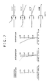
- FIG. 7 is diagrams showing spherical aberration, astigmatism, distortion and coma caused by a varifocal zoom lens in a numerical example 2 of the second embodiment in a shortest-focal-length lens state;
- FIG. 8 is diagrams showing spherical aberration, astigmatism, distortion and coma caused by the varifocal zoom lens in the numerical example 2 of the second embodiment in a middle-focal-length lens state;
- FIG. 9 is diagrams showing spherical aberration, astigmatism, distortion and coma caused by the varifocal zoom lens in the numerical example 2 of the second embodiment in a longest-focal-length lens state;
- FIG. 10 is a diagrammatic view of a varifocal zoom lens in a third embodiment according to the present invention.
- FIG. 11 is diagrams showing spherical aberration, astigmatism, distortion and coma caused by a varifocal zoom lens in a numerical example 3 of the varifocal zoom lens in the third embodiment in a shortest-focal-length lens state;
- FIG. 12 is diagrams showing spherical aberration, astigmatism, distortion and coma caused by the varifocal zoom lens in the numerical example 3 of the third embodiment in a middle-focal-length lens state;
- FIG. 13 is diagrams showing spherical aberration, astigmatism, distortion and coma caused by the varifocal zoom lens in numerical example 3 of the third embodiment in a longest-focal-length lens state;
- FIG. 14 is a diagrammatic view of a varifocal zoom lens in a fourth embodiment according to the present invention.
- FIG. 15 is diagrams showing spherical aberration, astigmatism, distortion and coma caused by a varifocal zoom lens in a numerical example 4 of the fourth embodiment in a shortest-focal-length lens state;
- FIG. 16 is diagrams showing spherical aberration, astigmatism, distortion and coma caused by the varifocal zoom lens in the numerical example 4 of the fourth embodiment in a middle-focal-length lens state;
- FIG. 17 is diagrams showing spherical aberration, astigmatism, distortion and coma caused by the varifocal zoom lens in the numerical example 4 of the fourth embodiment in a longest-focal-length lens state;
- FIG. 18 is a block diagram of a camera system embodying the present invention.
- FIGS. 19A and 19B are diagrammatic views of assistance in explaining outward coma.
- FIGS. 20A and 20B are diagrammatic views of assistance in explaining inward coma.
- a varifocal zoom lens includes a first lens group having a negative refractive power, a second lens group having a positive refractive power and disposed behind the first lens group with respect to an object side, and a third lens group having a positive refractive power and disposed behind the second lens group with respect to the object side. At least the first and the second lens groups are moved to change the lens state from a shortest-focal-length lens state for the largest field angle to a longest-focal-length lens state for the smallest field angle, and the second lens group is moved toward an object side so as to decrease an interval between the first and the second lens group.
- An aperture stop is disposed between the first and the second lens group.
- the lens state is changed from the shortest-focal-length lens state to the longest-focal-length lens state, the variation of off-axial aberration resulting from the variation of lens state is suppressed satisfactorily by taking advantage of the approach of off-axis light rays to the optical axis of the varifocal zoom lens.
- the second lens group of the varifocal zoom lens includes a cemented lens L 21 and a positive lens L 22 disposed on an image side with respect to the cemented lens L 21 and spaced from the cemented lens L 21 .
- the second lens group is formed in the so-called peripheral-contact structure in which the cemented lens L 21 and the positive lens L 22 touch each other outside the effective lens diameter.
- the shape of the cemented lens L 21 of the second lens group is designed so as to form the varifocal zoom lens system in a small size.
- lens groups respectively having high refractive powers are effective in miniaturizing a lens system.
- the decentration of lenses caused during manufacture exerts a considerably significant effect on the deterioration of the performance of the lens system.
- the front convex surface, on the object side, of the cemented lens component L 21 of the second lens group faces the aperture stop, off-axis light rays are caused to diverge greatly and are liable to cause off-axial aberration.
- the radius of curvature of the front convex surface of the cemented lens component L 21 are determined properly to suppress the deterioration of the performance due to the decentration of the lenses and to achieve the miniaturization of the lens system.
- the varifocal zoom lens of the present invention satisfies conditions expressed by: 0.02 ⁇ D s /( R 22 a ⁇ R 21 b ) ⁇ 0.1 (1) 0.6 ⁇ D a /R 21 b ⁇ 0.8 (2) where D s is the length of the air space between the cemented lens component L 21 and the positive lens component L 22 , R 22 a is the radius of curvature of the surface on the object side of the positive lens component L 22 , R 21 b is the radius of curvature of the surface on the image side of the cemented lens component L 21 , and D a is the distance between the aperture stop and the surface on the image side of the cemented lens component L 21 .
- the cemented lens component L 21 of the second lens group and the positive lens component L 22 of the second lens group disposed behind the cemented lens component L 21 and spaced from the cemented lens component L 21 are in direct touch with each other on the outside of the effective lens diameter when the cemented lens component L 21 and the positive lens element L 22 are disposed in a lens chamber without placing any spacer between the cemented lens component L 21 and the positive lens component L 22 .
- the cemented lens component L 21 and the positive lens component L 22 are able to touch each other only at a position greatly spaced apart from the optical axis and the lens diameter increases undesirably.
- the varifocal zoom lens of the present invention causes a higher spherical aberration by using the air space between the cemented lens component L 21 and the positive lens component L 22 disposed on the image side with respect to the cemented lens component L 21 and separated by the air space from the cemented lens component L 21 . If the upper limit specified by Expression (1) is 0.07 or below higher, spherical aberration can be satisfactorily caused for the further enhancement of the performance of the varifocal zoom lens.
- a value of D s /(R 22 a ⁇ R 21 b ) below the lower limit specified by Expression (1) is not desirable because negative distortion is extremely large in the shortest-focal-length lens state and it is difficult for the varifocal zoom lens system to exercise a predetermined optical performance due to a small higher spherical aberration caused by the air space between the cemented lens component L 21 and the positive lens component L 22 if D s /(R 22 a ⁇ R 21 b ) is below the lower limit specified by Expression (1)
- Expression (2) specifies the radii of curvature of the surfaces of the cemented lens component L 21 of the second lens group.
- the refractive power arrangement in the varifocal zoom lens system is extremely asymmetrical in the shortest-focal-length lens state if the first and the second lens group are spaced a long distance apart from each other. Therefore, the second lens group needs a lens having a concave surface facing the image side to cause positive distortion by the second lens group.
- the cemented lens component L 21 of the second lens group of the varifocal zoom lens of the present invention have a concave surface of a small radius of curvature on the image side.
- Expression (2) specifies a numerical range for a value, namely, the ratio of distance between the aperture stop and the surface on the image side of the cemented lens component L 21 to the radius of curvature of the same surface, namely, D a /R 21 b , for satisfactorily correcting negative distortion.
- the second lens group of the varifocal zoom lens of the present invention satisfying the conditions expressed by Expressions (1) and (2) has a simple construction, and the varifocal zoom lens can be sufficiently miniaturized.
- the varifocal zoom lens according to the embodiment of the present invention satisfies a condition expressed by: 1.8 ⁇
- Expression (3) specifies the focal length of the first lens group.
- the varifocal zoom lens has a long length in the longest-focal-length lens state. If the ratio
- the varifocal zoom lens according to the embodiment of the present invention satisfies, to achieve both miniaturization and performance enhancement in a well balanced mode, a condition expressed by either of expressions: ⁇ 0.3 ⁇ ( R 22 a +R 22 b )/( R 22 a ⁇ R 22 b ) ⁇ 0.2 (4) 1.6 ⁇ f 2 /f w ⁇ 2.1 (5) where R 22 b is the radius of curvature of the surface on the image side of the positive lens component L 22 , and f 2 is the focal length of the second lens group.
- Expression (4) specifies the shape of the positive lens included in the second lens group. If the ratio (R 22 a +R 22 b )/(R 22 a ⁇ R 22 b ) is above the upper limit specified by Expression (4), outward coma is liable to arise and the variation of coma with the variation of field angle in the shortest-focal-length lens state cannot be satisfactorily corrected.
- Outward coma is an image defect that forms a fuzzy image resembling the fuzzy tail of a comet and extending outward from a spot.
- Outward coma is, for example, an aberration that forms a fuzzy image x′ extending outward from a spot x and making the spot x look like a comet as shown in FIG. 19A .
- Inward coma is, for example, an aberration that forms a fuzzy image x′ extending inward from a spot x and making the spot x look like a comet as shown in FIG. 20A .
- FIG. 20B is a coma diagram showing the inward coma. If the ratio (R 22 a +R 22 b )/(R 22 a ⁇ R 22 b ) is below the lower limit specified by Expression (4), the air space between the cemented lens component L 21 and the positive lens component L 22 of the second lens group narrows when the cemented lens L 21 and the positive lens L 22 touch each other outside the effective lens diameter. Consequently, it is difficult to correct satisfactorily negative spherical aberration caused by the second lens group, and the variation of axial aberration with the variation of lens state (field angle) cannot be satisfactorily corrected.
- Expression (5) specifies the focal length of the second lens group. If the ratio f 2 /f 2 is above the upper limit specified by Expression (5), the axial distance between the first and the second lens group increases in the shortest-focal-length lens state. Consequently, off-axis light rays passing through the first lens group deviate from the optical axis and the lens diameter increases. If the ratio f 2 /f 2 is below the lower limit specified by Expression (5), correction of negative spherical aberration caused by the second lens group is difficult. When the varifocal zoom lens according to the embodiment of the present invention satisfies both Expressions (4) and (5), the varifocal zoom lens exercises high performance.
- the varifocal zoom lens of the present invention can be further miniaturized when the varifocal zoom lens of the present invention satisfies conditions expressed by expressions: ⁇ 2 /f w ⁇ 0.85 (6) TL w /f w ⁇ 6.5 (7)
- ⁇ 2 is the thickness of the second lens group and TL w is the length of the varifocal zoom lens in a shortest-focal-length lens state.
- Expression (6) specifies the lens thickness of the second lens group.
- the thickness of the body of a collapsible mount type camera that collapses a lens barrel and houses the collapsed lens barrel in the body increases undesirably with the increase of the respective thicknesses of the lens groups.
- the second lens group has a big thickness and the body of the camera is undesirably thick.
- Expression (7) specifies the total length of the varifocal zoom lens in the shortest-focal-length lens state.
- the total length of the varifocal zoom lens system of the present invention in the shortest-focal-length lens state is liable to increase. If the total length of the varifocal zoom lens collapsed to house the varifocal zoom lens in the body of the camera for carrying is long, the body of the camera is inevitably large.
- the lens state in the varifocal zoom lens of the present invention is changed from the shortest-focal-length lens state to the longest-focal-length lens state, the position of an image of an object at an infinite distance formed by the varifocal zoom lens is not continuously fixed.
- the varifocal zoom lens of the present invention may be combined with a detecting system for detecting change in the position of an image, a focusing system including a lens moving system for moving some of the lens components of the varifocal zoom lens along the optical axis, and a control system that determines values of manipulated variables of the driving system necessary for compensating the position of an image on the basis of output provided by the detecting system to form a lens system.
- the varifocal zoom lens can be a zoom lens in which the lens components thereof are moved with respect to each other to obtain a continuously variable focal length while the image is kept in the same image plane.
- the varifocal zoom lens of the present invention When the varifocal zoom lens of the present invention is focused on an object at a short distance, it is desirable that one of the lens groups moves or one of the lens components of one of the lens groups moves. It is preferable to move the third lens group because the variation of off-axis aberration due to the variation of the position of the object is small when the third lens group is moved.
- the position of the third lens group is fixed with respect to an image plane regardless of the lens state in the preferred embodiments to be described below, and the third lens group may be disposed at different positions respectively for the shortest-focal-length lens state and the middle-focal-length lens state.
- the varifocal zoom lens of the present invention may employ an aspherical lens to achieve higher optical performance. Further improvement of central performance, i.e., better correction of spherical aberration, can be achieved by using a lens having an aspherical surface facing the object as the lens nearest to the object of the second lens group. The variation of coma resulting from the variation of field angle in the shortest-focal-length lens state can be satisfactorily corrected by using an aspherical lens as one of the first lens group.
- optical performance of an optical system can be improved by providing the optical system with a plurality of aspherical surfaces.
- An image can be shifted by shifting one of the lens groups or one of the lens components of one of the lens groups of the varifocal zoom lens of the present invention in a direction substantially perpendicular to the optical axis.
- An antivibration optical system can be built by combining the varifocal zoom lens with a camera-shake detecting system, a driving system for shifting the lens groups, and a control system that determines values of manipulated variables of the driving system necessary for compensating the position of an image on the basis of output provided by the detecting system.
- An image can be shifted with a little variation of aberration by shifting the second lens group or the lens component of the second lens group in a direction substantially perpendicular to the optical axis. Since the second lens group is disposed near the aperture stop, the variation of coma due to the shift of the second lens group or the lens component of the second lens group is little because off-axis light rays pass near the optical axis.
- a low-pass filter may be disposed on the image side of the lens system to prevent the formation of moiré or an infrared cut filter may be disposed on the image side of the lens system as the spectral sensitivity characteristic of the light-receiving device needs.
- FIG. 1 shows the distribution of refractive power of a varifocal zoom lens in each of the preferred embodiments according to the present invention.
- a first lens group having a negative refractive power, a second lens group G 2 having a positive refractive power and a third lens group G 3 having a positive refractive power are arranged in that order from the object side, namely, the front side, toward the image side, namely, the back side.
- the second lens group G 2 is moved toward the object side, the first lens group G 1 is moved toward the object side after temporarily moving the first lens group G 1 toward the image side and the third lens group G 3 is kept stationary with respect to the optical axis so that the length of an air space between the first lens group G 1 and the second lens group G 2 increases and the length of an air space between the second lens group G 2 and the third lens group G 3 changes.
- the varifocal zoom lens in each of the preferred embodiments is provided with a protective glass plate in front of the first lens group.
- FIG. 2 shows a varifocal zoom lens 1 in a first embodiment according to the present invention.
- a first lens group G 1 includes a negative lens component L 11 having a concave surface facing the image side and a positive lens component L 12 having a convex surface facing the object side.
- a second lens group G 2 includes a cemented lens component L 21 including a positive lens having a convex surface facing the object side and a negative lens having a concave surface facing the image side and a biconvex positive lens component L 22 .
- a third lens group G 3 has a positive lens component L 3 .
- a contact edge Lm is formed in a surface on the image side of the cemented lens component L 21 of the second lens group G 2 in a circular area near and outside a circle of the effective diameter of the cemented lens component L 21 .
- a surface s 9 on the object side of the positive lens component L 22 is in contact with the contact edge Lm.
- the second lens group G 2 has the so-called peripheral-contact construction.
- an aperture stop S is disposed in front of the second group G 2 .
- the aperture stop S moves together with the second lens group G 2 when the lens state of the varifocal zoom lens 1 is changed.
- Table 1 shows numerical values of dimensions of a varifocal zoom lens in a numerical example 1 of the varifocal zoom lens in the first embodiment.
- s i indicates the i-th surface from the front
- r i indicates the radius of curvature of the i-th surface
- d i indicates the distance between the i-th surface and the i+1-th surface
- INFINITY indicates that the relevant surface is flat and “ASP” indicates that the relevant surface is an aspherical surface.
- the surface separation d 4 between the first lens group G 1 and the aperture stop S, the surface separation d 10 between the second lens group G 2 and the third lens group G 3 and the surface separation d 12 between the third lens group G 3 and a protective glass plate GL are variable when the lens state is changed.
- Table 2 shows values of the surface separations d 4 , D 10 and d 12 in the varifocal zoom lens in the numerical example 1 in a shortest-focal-length lens state, a middle-focal-length lens state and a longest-focal-length lens state, respectively, F numbers and field angles 2 ⁇ ° for focal lengths.
- the surface s 2 on the image side of the negative lens component L 11 of the first lens group G 1 and the surface S 6 on the object side of the cemented lens component L 21 of the second lens group G 2 are aspherical.
- Values of the fourth-order aspheric coefficient C 4 , the sixth-order aspheric coefficient C 6 , the eighth-order aspheric coefficient C 8 and the tenth-order aspheric coefficient C 10 and the conic coefficients ⁇ of the surfaces s 2 and S 6 are tabulated in Table 3.
- the varifocal zoom lens in the numerical example 1 is capable of satisfactorily correcting aberrations.
- FIG. 6 shows a varifocal zoom lens 2 in a second embodiment according to the present invention.
- a first lens group G 1 includes a negative lens component L 11 having a concave surface facing the image side and a positive lens component L 12 having a convex surface facing the object side.
- a second lens group G 2 includes a cemented lens component L 21 including a positive lens having a convex surface facing the object side and a negative lens having a concave surface facing the image side and a biconvex positive lens component L 22 .
- a third lens group G 3 has a positive lens component L 3 .
- a contact edge Lm is formed in a surface on the image side of the cemented lens component L 21 of the second lens group G 2 in a circular area near and outside a circle of the effective diameter of the cemented lens component L 21 .
- a surface s 9 on the object side of the positive lens component L 22 is in contact with the contact edge Lm.
- the second lens group G 2 has the so-called peripheral-contact construction.
- an aperture stop S is disposed in front of the second group G 2 .
- the aperture stop S moves together with the second lens group G 2 when the lens state of the varifocal zoom lens 2 is changed.
- Table 5 shows numerical values of dimensions of a varifocal zoom lens in a numerical example 2 of the varifocal zoom lens 2 in the second embodiment. Symbols shown in Table 5 are the same in meaning as those shown in Table 1.
- the surface separation d 4 between the first lens group G 1 and the aperture stop S, the surface separation d 10 between the second lens group G 2 and the third lens group G 3 and the surface separation d 12 between the third lens group G 3 and a protective glass plate GL are variable when the lens state is changed.
- Table 6 shows values of the surface separations d 4 , D 10 and d 12 in the varifocal zoom lens in the numerical example 2 in a shortest-focal-length lens state, a middle-focal-length lens state and a longest-focal-length lens state, respectively, F numbers and field angles 2 ⁇ ° for focal lengths.
- the surface s 2 on the image side of the negative lens component L 11 of the first lens group G 1 and the surface s 6 on the object side of the cemented lens component L 21 of the second lens group G 2 are aspherical.
- Values of the fourth-order aspheric coefficient C 4 , the sixth-order aspheric coefficient C 6 , the eighth-order aspheric coefficient C 8 and the tenth-order aspheric coefficient C 10 and the conic coefficients ⁇ of the surfaces s 2 and s 6 are tabulated in Table 7.
- a indicates field angle.
- the varifocal zoom lens in the numerical example 2 is capable of satisfactorily correcting aberrations and has an excellent image forming ability.
- FIG. 10 shows a varifocal zoom lens 3 in a third embodiment according to the present invention.
- a first lens group G 1 includes a negative lens component L 11 having a concave surface facing the image side and a positive lens component L 12 having a convex surface facing the object side.
- a second lens group G 2 includes a cemented lens component L 21 including a positive lens having a convex surface facing the object side and a negative lens having a concave surface facing the image side and a biconvex positive lens component L 22 .
- a third lens group G 3 has a positive lens component L 3 .
- a contact edge Lm is formed in a surface on the image side of the cemented lens component L 21 of the second lens group G 2 in a circular area near and outside a circle of the effective diameter of the cemented lens component L 21 .
- a surface s 9 on the object side of the positive lens component L 22 is in contact with the contact edge Lm.
- the second lens group G 2 has the so-called peripheral-contact construction.
- an aperture stop S is disposed in front of the second group G 2 .
- the aperture stop S moves together with the second lens group G 2 when the lens state of the varifocal zoom lens 3 is changed.
- Table 9 shows numerical values of dimensions of a varifocal zoom lens in a numerical example 3 of the varifocal zoom lens 3 in the third embodiment. Symbols shown in Table 9 are the same in meaning as those shown in Table 1.
- the surface separation d 4 between the first lens group G 1 and the aperture stop S, the surface separation d 10 between the second lens group G 2 and the third lens group G 3 and the surface separation d 12 between the third lens group G 3 and a protective glass plate GL are variable when the lens state is changed.
- Table 10 shows values of the surface separations d 4 , d 10 and d 12 in the varifocal zoom lens in the numerical example 3 in a shortest-focal-length lens state, a middle-focal-length lens state and a longest-focal-length lens state, respectively, F numbers and field angles 2 ⁇ ° for focal lengths.
- the surface s 2 on the image side of the negative lens component L 11 of the first lens group G 1 and the surface s 6 on the object side of the cemented lens component L 21 of the second lens group G 2 are aspherical.
- Values of the fourth-order aspheric coefficient C 4 , the sixth-order aspheric coefficient C 6 , the eighth-order aspheric coefficient C 8 and the tenth-order aspheric coefficient C 10 and the conic coefficients ⁇ of the surfaces s 2 and s 6 are tabulated in Table 11.
- continuous lines and broken lines indicate sagittal image surfaces and meridional image surfaces, respectively.
- “A” indicates field angle.
- the varifocal zoom lens in the numerical example 3 is capable of satisfactorily correcting aberrations and has an excellent image forming ability.
- FIG. 14 shows a varifocal zoom lens 4 in a fourth embodiment according to the present invention.
- a first lens group G 1 includes a negative lens component L 11 having a concave surface facing the image side and a positive lens component L 12 having a convex surface facing the object side.
- a second lens group G 2 includes a cemented lens component L 21 including a positive lens having a convex surface facing the object side and a negative lens having a concave surface facing the image side and a biconvex positive lens component L 22 .
- a third lens group G 3 has a positive lens component L 3 .
- a contact edge Lm is formed in a surface on the image side of the cemented lens component L 21 of the second lens group G 2 in a circular area near and outside a circle of the effective diameter of the cemented lens component L 21 .
- a surface s 9 on the object side of the positive lens component L 22 is in contact with the contact edge Lm.
- the second lens group G 2 has the so-called peripheral-contact construction.
- an aperture stop S is disposed in front of the second group G 2 .
- the aperture stop S moves together with the second lens group G 2 when the lens state of the varifocal zoom lens 4 is changed.
- Table 13 shows numerical values of dimensions of a varifocal zoom lens in a numerical example 4 of the varifocal zoom lens 4 in the fourth embodiment. Symbols shown in Table 9 are the same in meaning as those shown in Table 1.
- the surface separation d 4 between the first lens group G 1 and the aperture stop S, the surface separation d 10 between the second lens group G 2 and the third lens group G 3 and the surface separation d 12 between the third lens group G 3 and a protective glass plate GL are variable when the lens state is changed.
- Table 14 shows values of the surface separations d 4 , d 10 and d 12 in the varifocal zoom lens in the numerical example 4 in a shortest-focal-length lens state, a middle-focal-length lens state and a longest-focal-length lens state, respectively, F numbers and field angles 2 ⁇ ° for focal lengths.
- the surface s 2 on the image side of the negative lens component L 11 of the first lens group G 1 and the surface S 6 on the object side of the cemented lens component L 21 of the second lens group G 2 are aspherical.
- Values of the fourth-order aspheric coefficient C 4 , the sixth-order aspheric coefficient C 6 , the eighth-order aspheric coefficient C 8 and the tenth-order aspheric coefficient C 10 and the conic coefficients ⁇ of the surfaces s 2 and s 6 are tabulated in Table 15.
- continuous lines and broken lines indicate sagittal image surfaces and meridional image surfaces, respectively.
- “A” indicates field angle.
- the varifocal zoom lens in the numerical example 4 is capable of satisfactorily correcting aberrations and has an excellent image forming ability.
- FIG. 18 shows a camera system 10 embodying the present invention.
- the camera system 10 includes a varifocal zoom lens 20 and an image pickup device 30 for converting optical image formed by the varifocal zoom lens 20 into electric signals.
- the image pickup device 30 is provided with a photoelectric converter, such as a CCD (charge-coupled device) or a CMOS device (complementary metal-oxide semiconductor device).
- the varifocal zoom lens 20 may be any one of the varifocal zoom lenses in the first to the fourth embodiment.
- the image pickup device 30 gives an electric signal to an image separating circuit 40 .
- the image separating circuit 40 divides the electric signal into an image forming signal and a focusing signal.
- the image separating circuit 40 gives the focusing signal to a focusing control circuit 50 , and gives the image forming signal to an image processing unit.
- the image forming signal given to the image processing circuit is processed to produce an easy-to-process image signal.
- the image signal thus produced is used for displaying an image on a display, storing image data in a recording medium and transferring image data to other devices.
- An external operation signal is given to the focusing control circuit 50 by operating an operation control button, such as a zoom button.
- an operation control button such as a zoom button.
- drivers 60 , 70 and 80 drive, for example, drive devices, such as motors 61 , 71 and 81 , so that the first lens group G 1 , the second lens group G 2 and the third lens group G 3 are moved to predetermined positions to set the varifocal zoom lens 20 for a desired focal length.
- Position signals provided by sensors 62 , 72 and 82 and representing the respective positions of the first lens group G 1 , the second lens group G 2 and the third lens group G 3 are given to the focusing control circuit 50 , and then the focusing control circuit 50 generates command signals to be given to the drivers 60 , 70 and 80 on the basis of the input signals.
- the focusing control circuit 50 examines the focusing condition on the basis of the signal given thereto by the image separating circuit 40 and controls, for example, the drive circuit 80 to move the third lens group G 3 so that the varifocal zoom lens 20 is focused in an optimum accuracy.
- the camera system 10 is one of various products.
- the camera system 10 can be widely used as a camera unit for digital input/output apparatuses including, for example, digital still cameras, digital video cameras, portable telephones with a camera, and PDAs (personal digital assistants) with a camera.
- digital input/output apparatuses including, for example, digital still cameras, digital video cameras, portable telephones with a camera, and PDAs (personal digital assistants) with a camera.
Landscapes
- Physics & Mathematics (AREA)
- General Physics & Mathematics (AREA)
- Optics & Photonics (AREA)
- Nonlinear Science (AREA)
- Lenses (AREA)
Abstract
0.02<D s/(R22 a −R21 b)<0.1 (1)
0.6<D a /R21 b<0.8 (2)
where Ds is the length of an air space between the cemented lens component L21 and the positive lens component L22, R22 a is the radius of curvature of the surface on the object side of the positive lens component L22, R21 b is the radius of curvature of the surface on the image side of the cemented lens component L21, and Da is the distance between the aperture stop and the surface on the image side of the cemented lens component L21.
Description
0.02<D s/(R22a −R21b)<0.1 (1)
0.6<D a /R21b<0.8 (2)
where Ds is the length of an air space between the cemented lens component L21 and the positive lens component L22, R22 a is the radius of curvature of the surface on the object side of the positive lens component L22, R21 b is the radius of curvature of the surface on the image side of the cemented lens component L21, and Da is the distance between the aperture stop and the surface on the image side of the cemented lens component L21.
0.02<D s/(R22a −R21b)<0.1 (1)
0.6<D a /R21b<0.8 (2)
where Ds is the length of the air space between the cemented lens component L21 and the positive lens component L22, R22 a is the radius of curvature of the surface on the object side of the positive lens component L22, R21 b is the radius of curvature of the surface on the image side of the cemented lens component L21, and Da is the distance between the aperture stop and the surface on the image side of the cemented lens component L21.
1.8<|f 1 |/f w<2.3 (3)
where f1 is the focal length of the first lens group, and fw is the focal length of the varifocal zoom lens in the shortest-focal-length lens state.
−0.3<(R22a +R22b)/(R22a −R22b)<0.2 (4)
1.6<f 2 /f w<2.1 (5)
where R22 b is the radius of curvature of the surface on the image side of the positive lens component L22, and f2 is the focal length of the second lens group.
Σ2/f w<0.85 (6)
TL w /f w<6.5 (7)
0.02<D s/(R22a −R21b)<0.1 (1)
0.6<D a /R21b<0.8 (2)
where Ds is the length of the air space between the cemented lens component L21 and the positive lens component L22, R22 a is the radius of curvature of the surface on the object side of the positive lens component L22, R21 b is the radius of curvature of the surface on the image side of the cemented lens component L21, and Da is the distance between the aperture stop and the surface on the image side of the cemented lens component L21.
1.8<|f 1 /f w<2.3 (3)
where f1 is the focal length of the first lens group, and fw is the focal length of the varifocal zoom lens in the shortest-focal-length lens state. Expression (3) specifies the focal length of the first lens group.
−0.3<(R22 a +R22 b)/(R22 a −R22 b)<0.2 (4)
1.6<f 2 /f w<2.1 (5)
where R22 b is the radius of curvature of the surface on the image side of the positive lens component L22, and f2 is the focal length of the second lens group.
Σ2/f w<0.85 (6)
TL w /f w<6.5 (7)
-
- Aspherical surfaces in the preferred embodiments are defined by:
x=cy 2/[1+{1−(1+κ)c 2 y 2}1/2 ]+C 4 y 4 +C 6 y 6+ . . .
where y is the height from the optical axis, x is sag, c is the curvature, κ is the conic coefficient and C4, C6 are aspherical coefficients.
- Aspherical surfaces in the preferred embodiments are defined by:
| TABLE 1 | ||||
| si | ri | di | ni | νi |
| 1 | r1 = 23.9432 | d1 = 0.124 | n1 = 1.74432 | ν1 = 49.2 |
| 2 | r2 = 0.8326(ASP) | d2 = 0.358 | ||
| 3 | r3 = 1.6598 | d3 = 0.173 | n2 = 1.84666 | ν2 = 23.8 |
| 4 | r4 = 4.4809 | d4 = variable | ||
| 5 | r5 = INFINITY | d5 = 0.012 | Aperture stop | |
| 6 | r6 = 0.8025(ASP) | d6 = 0.427 | n3 = 1.80610 | ν3 = 40.7 |
| 7 | r7 = 1.7051 | d7 = 0.100 | n4 = 1.92286 | ν4 = 20.9 |
| 8 | r8 = 0.7035 | d8 = 0.075 | ||
| 9 | r9 = 2.0012 | d9 = 0.194 | n5 = 1.65160 | ν5 = 58.4 |
| 10 | r10 = −2.5854 | d10 = variable | ||
| 11 | r11 = 2.0719 | d11 = 0.212 | n6 = 1.49700 | ν6 = 80.2 |
| 12 | r12 = 82.9807 | d12 = variable | ||
| 13 | r13 = INFINITY | d13 = 0.406 | n7 = 1.51633 | ν7 = 64.2 |
| Protective | ||||
| glass plate | ||||
| 14 | r14 = INFINITY | Back focus | ||
| TABLE 2 | ||
| Focal length | ||
| 1.000 | 1.581 | 3.296 | ||
| F number | 2.88 | 3.75 | 5.69 | ||
| 2ω (°) | 63.02 | 41.34 | 20.12 | ||
| d4 | 2.454 | 1.326 | 0.315 | ||
| d10 | 1.363 | 2.060 | 4.118 | ||
| d12 | 0.279 | 0.279 | 0.279 | ||
| Back focus | 0.183 | 0.183 | 0.183 | ||
| TABLE 3 | |||||
| si | κ | C4 | C6 | C8 | C10 |
| 2 | −1.8675 | +0.22999 × 10−0 | −0.71376 × 10⁻¹ | +0.00000 | +0.00000 |
| 6 | −0.6823 | +0.67478 × 10⁻¹ | +0.12900 × 10−0 | −0.14122 × 10−0 | +0.33428 × 10−0 |
| TABLE 4 | |||
| f1 | −2.011 | ||
| f2 | +1.919 | ||
| (1)Ds/(R22a − R21b) | 0.058 | ||
| (2)Da/R21b | 0.766 | ||
| (3)|f1|/fw | −2.011 | ||
| (4)(R22a + R22b)/(R22a − R22b) | −0.127 | ||
| (5)f2/fw | 1.919 | ||
| (6) |
0.796 | ||
| (7)TLw/fw | 6.360 | ||
| TABLE 5 | ||||
| si | ri | di | ni | νi |
| 1 | r1 = 15.3786 | d1 = 0.134 | n1 = 1.77250 | ν1 = 49.6 |
| 2 | r2 = 0.8810(ASP) | d2 = 0.449 | ||
| 3 | r3 = 1.8130 | d3 = 0.170 | n2 = 1.84666 | ν2 = 23.8 |
| 4 | r4 = 3.9849 | d4 = variable | ||
| 5 | r5 = INFINITY | d5 = 0.013 | Aperture stop | |
| 6 | r6 = 0.7917(ASP) | d6 = 0.429 | n3 = 1.80610 | ν3 = 40.7 |
| 7 | r7 = 1.7990 | d7 = 0.107 | n4 = 1.92286 | ν4 = 20.9 |
| 8 | r8 = 0.6948 | d8 = 0.077 | ||
| 9 | r9 = 2.2859 | d9 = 0.186 | n5 = 1.72916 | ν5 = 54.7 |
| 10 | r10 = −2.9293 | d10 = variable | ||
| 11 | r11 = 2.0847 | d11 = 0.229 | n6 = 1.49700 | ν6 = 80.2 |
| 12 | r12 = 87.2758 | d12 = variable | ||
| 13 | r13 = INFINITY | d13 = 0.437 | n7 = 1.51633 | ν7 = 64.2 |
| Protective | ||||
| glass plate | ||||
| 14 | r14 = INFINITY | Back focus | ||
| TABLE 6 | ||
| Focal length | ||
| 1.000 | 1.701 | 2.826 | ||
| F number | 2.88 | 3.73 | 5.12 | ||
| 2ω (°) | 66.83 | 41.34 | 25.21 | ||
| d4 | 2.369 | 1.079 | 0.346 | ||
| d10 | 1.225 | 2.051 | 3.378 | ||
| d12 | 0.300 | 0.300 | 0.300 | ||
| Back focus | 0.196 | 0.196 | 0.196 | ||
| TABLE 7 | |||||
| si | κ | C4 | C6 | C8 | C10 |
| 2 | −1.9870 | +0.21279 × 10−0 | −0.61470 × 10⁻¹ | +0.00000 | +0.00000 |
| 6 | −0.3942 | +0.62924 × 10⁻² | +0.12817 × 10−0 | −0.47535 × 10−0 | +0.94302 × 10−0 |
| TABLE 8 | |||
| f1 | −2.087 | ||
| f2 | +1.921 | ||
| (1)Ds/(R22a − R21b) | 0.048 | ||
| (2)Da/R21b | 0.790 | ||
| (3)|f1|/fw | −2.087 | ||
| (4)(R22a + R22b)/(R22a − R22b) | −0.123 | ||
| (5)f2/fw | 1.921 | ||
| (6) |
0.799 | ||
| (7)TLw/fw | 6.323 | ||
| TABLE 9 | ||||
| si | ri | di | ni | νi |
| 1 | r1 = 11.7360 | d1 = 0.124 | n1 = 1.77250 | ν1 = 49.6 |
| 2 | r2 = 0.8326(ASP) | d2 = 0.354 | ||
| 3 | r3 = 1.5333 | d3 = 0.170 | n2 = 1.84666 | ν2 = 23.8 |
| 4 | r4 = 3.3112 | d4 = variable | ||
| 5 | r5 = INFINITY | d5 = 0.012 | Aperture stop | |
| 6 | r6 = 0.7050(ASP) | d6 = 0.324 | n3 = 1.80610 | ν3 = 40.7 |
| 7 | r7 = 1.4780 | d7 = 0.100 | n4 = 1.92286 | ν4 = 20.9 |
| 8 | r8 = 0.6343 | d8 = 0.088 | ||
| 9 | r9 = 2.6180 | d9 = 0.171 | n5 = 1.72916 | ν5 = 54.7 |
| 10 | r10 = −2.4627 | d10 = variable | ||
| 11 | r11 = 2.1716 | d11 = 0.193 | n6 = 1.49700 | ν6 = 80.2 |
| 12 | r12 = 82.9807 | d12 = variable | ||
| 13 | r13 = INFINITY | d13 = 0.406 | n7 = 1.51633 | ν7 = 64.2 |
| Protective | ||||
| glass plate | ||||
| 14 | r14 = INFINITY | Back focus | ||
| TABLE 10 | ||
| Focal length | ||
| 1.000 | 1.581 | 2.826 | ||
| F number | 2.88 | 3.56 | 5.05 | ||
| 2ω (°) | 63.04 | 41.39 | 23.46 | ||
| d4 | 2.345 | 1.199 | 0.330 | ||
| d10 | 1.281 | 1.909 | 3.258 | ||
| d12 | 0.279 | 0.279 | 0.279 | ||
| Back focus | 0.183 | 0.183 | 0.183 | ||
| TABLE 11 | |||||
| si | κ | C4 | C6 | C8 | C10 |
| 2 | −1.8370 | +0.24770 × 10−0 | −0.58783 × 10⁻¹ | +0.00000 | +0.00000 |
| 6 | −0.2459 | +0.50755 × 10⁻¹ | +0.15749 × 10−0 | −0.11053 × 10+1 | +0.23610 × 10+1 |
| TABLE 12 | |||
| f1 | −2.101 | ||
| f2 | +1.837 | ||
| (1)Ds/(R22a − R21b) | 0.044 | ||
| (2)Da/R21b | 0.683 | ||
| (3)|f1|/fw | −2.101 | ||
| (4)(R22a + R22b)/(R22a − R22b) | +0.030 | ||
| (5)f2/fw | 1.837 | ||
| (6) |
0.683 | ||
| (7)TLw/fw | 6.030 | ||
| TABLE 13 | ||||
| si | ri | di | ni | νi |
| 1 | r1 = 11.5284 | d1 = 0.124 | n1 = 1.08420 | ν1 = 46.5 |
| 2 | r2 = 0.8326(ASP) | d2 = 0.342 | ||
| 3 | r3 = 1.5284 | d3 = 0.174 | n2 = 1.84666 | ν2 = 23.8 |
| 4 | r4 = 3.4877 | d4 = variable | ||
| 5 | r5 = INFINITY | d5 = 0.012 | Aperture stop | |
| 6 | r6 = 0.7236(ASP) | d6 = 0.346 | n3 = 1.80610 | ν3 = 40.7 |
| 7 | r7 = 1.5617 | d7 = 0.100 | n4 = 1.92286 | ν4 = 20.9 |
| 8 | r8 = 0.6491 | d8 = 0.084 | ||
| 9 | r9 = 2.5257 | d9 = 0.172 | n5 = 1.72916 | ν5 = 54.7 |
| 10 | r10 = −2.4636 | d10 = variable | ||
| 11 | r11 = 2.3033 | d11 = 0.184 | n6 = 1.49700 | ν6 = 80.2 |
| 12 | r12 = 82.9807 | d12 = variable | ||
| 13 | r13 = INFINITY | d13 = 0.406 | n7 = 1.51633 | ν7 = 64.2 |
| Protective | ||||
| glass plate | ||||
| 14 | r14 = INFINITY | Back focus | ||
| TABLE 14 | ||
| Focal length | ||
| 1.000 | 1.581 | 2.826 | ||
| F number | 2.88 | 3.56 | 5.03 | ||
| 2 ω (°) | 63.04 | 41.39 | 23.46 | ||
| d4 | 2.367 | 1.208 | 0.328 | ||
| d10 | 1.256 | 1.869 | 3.183 | ||
| d12 | 0.279 | 0.279 | 0.278 | ||
| Back focus | 0.183 | 0.183 | 0.183 | ||
| TABLE 15 | |||||
| si | κ | C4 | C6 | C8 | C10 |
| 2 | −1.7726 | +0.2360 × 10−0 | −0.5112 × 10⁻¹ | +0.00000 | +0.00000 |
| 6 | −0.1884 | +0.6921 × 10⁻¹ | +0.1118 × 10−0 | −0.1041 × 10+1 | +0.2051 × 10+1 |
| TABLE 16 | |||
| f1 | −2.108 | ||
| f2 | +1.825 | ||
| (1)Ds/(R22a − R21b) | 0.041 | ||
| (2)Da/R21b | 0.706 | ||
| (3)|f1|/fw | −2.108 | ||
| (4)(R22a + R22b)/(R22a − R22b) | +0.012 | ||
| (5)f2/fw | 1.825 | ||
| (6) |
0.702 | ||
| (7)TLw/fw | 6.034 | ||
Claims (17)
0.02<D s/(R22a −R21b)<0.1 (1)
0.6<D a /R21b<0.8 (2)
1.8<|f 1 |/f w<2.3 (3)
−0.3<(R22a +R22b)/(R22a −R22b)<0.2 (4)
1.6<f 2 /f w<2.1 (5)
−0.3<(R22a +R22b)/(R22a −R22b)<0.2 (4)
1.6<f 2 /f w<2.1 (5)
−0.3<(R22a +R22b)/(R22a −R22b)<0.2 (4)
1.6<f 2 /f w<2.1 (5)
−0.3<(R22a +R22b)/(R22a −R22b)<0.2 (4)
1.6<f 2 /f w<2.1 (5)
Σ2/f w<0.85 (6)
TL w /f w<6.5 (7)
Σ2/f w<0.85 (6)
TL w /f w<6.5 (7)
Σ2/f w<0.85 (6)
TL w /f w<6.5 (7)
Σ2/f w<0.85 (6)
TL w /f w<6.5 (7)
Σ2/f w<0.85 (6)
TL w /f w<6.5 (7)
Σ2/f w<0.85 (6)
TL w /f w<6.5 (7)
0.02<D s/(R22a −R21b)<0.1 (1)
0.6<D a /R21b<0.8 (2)
0.02<D s/(R22a −R21b)<0.1 (1)
0.6<D a /R21b<0.8 (2)
1.8<|f1|/fw<2.3
Applications Claiming Priority (2)
| Application Number | Priority Date | Filing Date | Title |
|---|---|---|---|
| JP2004172916A JP4210935B2 (en) | 2004-06-10 | 2004-06-10 | Variable focal length lens system and imaging apparatus |
| JPP2004-172916 | 2004-06-10 |
Publications (2)
| Publication Number | Publication Date |
|---|---|
| US20050275951A1 US20050275951A1 (en) | 2005-12-15 |
| US7133215B2 true US7133215B2 (en) | 2006-11-07 |
Family
ID=34942388
Family Applications (1)
| Application Number | Title | Priority Date | Filing Date |
|---|---|---|---|
| US11/144,841 Expired - Fee Related US7133215B2 (en) | 2004-06-10 | 2005-06-06 | Varifocal zoom lens and camera system |
Country Status (5)
| Country | Link |
|---|---|
| US (1) | US7133215B2 (en) |
| EP (1) | EP1605291B1 (en) |
| JP (1) | JP4210935B2 (en) |
| CN (2) | CN101241227A (en) |
| DE (1) | DE602005003263T2 (en) |
Cited By (4)
| Publication number | Priority date | Publication date | Assignee | Title |
|---|---|---|---|---|
| US20100097708A1 (en) * | 2007-01-30 | 2010-04-22 | Panasonic Corporation | Zoom lens system, imaging device and camera |
| US20100265594A1 (en) * | 2009-04-21 | 2010-10-21 | Sony Corporation | Zoom lens and imaging apparatus |
| US20120140106A1 (en) * | 2009-07-17 | 2012-06-07 | Largan Precision Co., Ltd. | Imaging lens system |
| US20120162497A1 (en) * | 2010-12-28 | 2012-06-28 | Panasonic Corporation | Zoom Lens System, Imaging Device and Camera |
Families Citing this family (13)
| Publication number | Priority date | Publication date | Assignee | Title |
|---|---|---|---|---|
| JP2006139164A (en) * | 2004-11-15 | 2006-06-01 | Konica Minolta Photo Imaging Inc | Variable power optical system |
| CN100397136C (en) * | 2006-09-12 | 2008-06-25 | 亚洲光学股份有限公司 | Zoom lens |
| JP2008164724A (en) * | 2006-12-27 | 2008-07-17 | Sony Corp | Zoom lens and imaging device |
| JP5179519B2 (en) | 2008-01-28 | 2013-04-10 | パナソニック株式会社 | Zoom lens system, imaging device and camera |
| TWI408410B (en) * | 2009-01-09 | 2013-09-11 | Hon Hai Prec Ind Co Ltd | Optical zoom lens system |
| WO2011001663A1 (en) * | 2009-07-02 | 2011-01-06 | パナソニック株式会社 | Zoom lens system, image pickup device and camera |
| CN102455492A (en) * | 2010-10-15 | 2012-05-16 | 广圆光电股份有限公司 | Miniature zoom lens |
| WO2013031188A1 (en) * | 2011-08-29 | 2013-03-07 | 富士フイルム株式会社 | Zoom lens and imaging device |
| WO2014129156A1 (en) * | 2013-02-19 | 2014-08-28 | 株式会社ニコン | Optical system, optical apparatus, and method for manufacturing optical system |
| JP5852764B2 (en) * | 2013-03-26 | 2016-02-03 | 富士フイルム株式会社 | Imaging lens and imaging apparatus |
| DE102020101474B3 (en) * | 2020-01-22 | 2021-05-12 | Carl Zeiss Ag | Camera zoom lens, optical imaging device, control unit, method for controlling an aperture diaphragm, computer program and computer-readable data carrier |
| CN113484998B (en) * | 2021-06-30 | 2023-03-24 | 江西晶浩光学有限公司 | Optical system, image capturing module with same and electronic device |
| CN113495347B (en) * | 2021-09-07 | 2021-12-07 | 沂普光电(天津)有限公司 | Ultra-short-focus lens |
Citations (9)
| Publication number | Priority date | Publication date | Assignee | Title |
|---|---|---|---|---|
| US5559635A (en) | 1993-08-27 | 1996-09-24 | Nikon Corporation | Zoom lens system capable of correcting image position |
| EP1093000A2 (en) | 1999-10-06 | 2001-04-18 | Canon Kabushiki Kaisha | Zoom lens and optical apparatus having the same |
| US6417973B2 (en) * | 2000-05-23 | 2002-07-09 | Olympus Optical Co., Ltd. | Electronic image pickup equipment |
| JP2003066332A (en) | 2001-08-22 | 2003-03-05 | Nikon Corp | Zoom lens |
| JP2003140047A (en) | 2001-10-30 | 2003-05-14 | Canon Inc | Zoom lens and optical apparatus having the same |
| JP2003140041A (en) | 2001-10-31 | 2003-05-14 | Pentax Corp | Zoom lens system |
| JP2003149555A (en) | 2001-11-16 | 2003-05-21 | Olympus Optical Co Ltd | Zoom lens and electronic image pickup device using the same |
| US6844986B2 (en) * | 2000-11-02 | 2005-01-18 | Canon Kabushiki Kaisha | Zoom lens and image taking apparatus using the same |
| US6943962B2 (en) * | 2003-05-06 | 2005-09-13 | Canon Kabushiki Kaisha | Zoom lens system |
Family Cites Families (3)
| Publication number | Priority date | Publication date | Assignee | Title |
|---|---|---|---|---|
| JP2003057547A (en) * | 2001-08-14 | 2003-02-26 | Canon Inc | Zoom lens and optical apparatus having the same |
| US7002755B2 (en) * | 2001-11-26 | 2006-02-21 | Olympus Corporation | Zoom lens, and electronic imaging system using the same |
| JP4138324B2 (en) * | 2001-11-28 | 2008-08-27 | 松下電器産業株式会社 | Zoom lens and video camera using the same |
-
2004
- 2004-06-10 JP JP2004172916A patent/JP4210935B2/en not_active Expired - Fee Related
-
2005
- 2005-06-06 US US11/144,841 patent/US7133215B2/en not_active Expired - Fee Related
- 2005-06-08 DE DE602005003263T patent/DE602005003263T2/en not_active Expired - Lifetime
- 2005-06-08 EP EP05291229A patent/EP1605291B1/en not_active Expired - Lifetime
- 2005-06-10 CN CNA2008100740528A patent/CN101241227A/en active Pending
- 2005-06-10 CN CNB2005100913063A patent/CN100381856C/en not_active Expired - Fee Related
Patent Citations (11)
| Publication number | Priority date | Publication date | Assignee | Title |
|---|---|---|---|---|
| US5559635A (en) | 1993-08-27 | 1996-09-24 | Nikon Corporation | Zoom lens system capable of correcting image position |
| EP1093000A2 (en) | 1999-10-06 | 2001-04-18 | Canon Kabushiki Kaisha | Zoom lens and optical apparatus having the same |
| US6417973B2 (en) * | 2000-05-23 | 2002-07-09 | Olympus Optical Co., Ltd. | Electronic image pickup equipment |
| US6538824B1 (en) * | 2000-05-23 | 2003-03-25 | Olympus Optical Co., Ltd. | Electronic image pickup equipment |
| US6844986B2 (en) * | 2000-11-02 | 2005-01-18 | Canon Kabushiki Kaisha | Zoom lens and image taking apparatus using the same |
| JP2003066332A (en) | 2001-08-22 | 2003-03-05 | Nikon Corp | Zoom lens |
| JP2003140047A (en) | 2001-10-30 | 2003-05-14 | Canon Inc | Zoom lens and optical apparatus having the same |
| JP2003140041A (en) | 2001-10-31 | 2003-05-14 | Pentax Corp | Zoom lens system |
| JP2003149555A (en) | 2001-11-16 | 2003-05-21 | Olympus Optical Co Ltd | Zoom lens and electronic image pickup device using the same |
| US20030189762A1 (en) | 2001-11-16 | 2003-10-09 | Olympus Optical Co., Ltd. | Zoom lens, and electronic imaging system using the same |
| US6943962B2 (en) * | 2003-05-06 | 2005-09-13 | Canon Kabushiki Kaisha | Zoom lens system |
Non-Patent Citations (2)
| Title |
|---|
| EPO Search Report mailed Feb. 10, 2006. |
| Partial EPO Search Report mailed Oct. 27, 2005. |
Cited By (10)
| Publication number | Priority date | Publication date | Assignee | Title |
|---|---|---|---|---|
| US20100097708A1 (en) * | 2007-01-30 | 2010-04-22 | Panasonic Corporation | Zoom lens system, imaging device and camera |
| US20100128362A1 (en) * | 2007-01-30 | 2010-05-27 | Panasonic Corporation | Zoom lens system, imaging device and camera |
| US8098442B2 (en) * | 2007-01-30 | 2012-01-17 | Panasonic Corporation | Zoom lens system, imaging device and camera |
| US8179611B2 (en) | 2007-01-30 | 2012-05-15 | Panasonic Corporation | Zoom lens system, imaging device and camera |
| US20100265594A1 (en) * | 2009-04-21 | 2010-10-21 | Sony Corporation | Zoom lens and imaging apparatus |
| US7880974B2 (en) * | 2009-04-21 | 2011-02-01 | Sony Corporation | Zoom lens and imaging apparatus |
| US20120140106A1 (en) * | 2009-07-17 | 2012-06-07 | Largan Precision Co., Ltd. | Imaging lens system |
| US8526115B2 (en) * | 2009-07-17 | 2013-09-03 | Largan Precision Co., Ltd. | Imaging lens system |
| US20120162497A1 (en) * | 2010-12-28 | 2012-06-28 | Panasonic Corporation | Zoom Lens System, Imaging Device and Camera |
| US8885265B2 (en) * | 2010-12-28 | 2014-11-11 | Panasonic Corporation | Zoom lens system, imaging device and camera |
Also Published As
| Publication number | Publication date |
|---|---|
| CN1715986A (en) | 2006-01-04 |
| CN100381856C (en) | 2008-04-16 |
| CN101241227A (en) | 2008-08-13 |
| DE602005003263D1 (en) | 2007-12-27 |
| EP1605291B1 (en) | 2007-11-14 |
| JP4210935B2 (en) | 2009-01-21 |
| US20050275951A1 (en) | 2005-12-15 |
| DE602005003263T2 (en) | 2008-09-18 |
| JP2005352182A (en) | 2005-12-22 |
| EP1605291A3 (en) | 2006-03-29 |
| EP1605291A2 (en) | 2005-12-14 |
Similar Documents
| Publication | Publication Date | Title |
|---|---|---|
| US7061686B2 (en) | Variable focal length lens system | |
| CN101063745B (en) | Variable focal length lens system and imaging device | |
| CN100538427C (en) | Zoom lens and image pick-up device | |
| CN100480771C (en) | Zoom lens and image pickup device | |
| US6992835B2 (en) | Zoom lens and imaging device | |
| US7133215B2 (en) | Varifocal zoom lens and camera system | |
| US7385766B2 (en) | Variable focal length lens system and image capturing apparatus | |
| JP3729126B2 (en) | Zoom lens | |
| JP4650676B2 (en) | Zoom lens and imaging device | |
| US7177095B2 (en) | Zoom lens and imaging apparatus having the same | |
| JP2010181787A (en) | Zoom lens and image pickup apparatus using the same | |
| JP4325209B2 (en) | Variable focal length lens system | |
| US7920333B2 (en) | Variable focal distance lens system and imaging device | |
| US7319562B2 (en) | Zoom lens system and image pickup apparatus including the zoom lens system | |
| JP2004212616A (en) | Variable focal length lens system | |
| EP3064979A1 (en) | Zoom lens and photographing apparatus including the same | |
| JP7425616B2 (en) | Optical system and imaging device | |
| JP4441856B2 (en) | Variable focal length lens system and imaging apparatus | |
| JP4479151B2 (en) | Variable focal length lens system | |
| JP2004333572A (en) | Variable focal length lens system | |
| JP7191884B2 (en) | Imaging lens and imaging device | |
| JP2008310364A (en) | Variable focal length lens system and imaging apparatus | |
| JP2007127694A (en) | Zoom lens and imaging device | |
| JP7794628B2 (en) | Optical system and imaging device | |
| US20250102783A1 (en) | Zoom lens and image pickup apparatus having the same |
Legal Events
| Date | Code | Title | Description |
|---|---|---|---|
| AS | Assignment |
Owner name: SONY CORPORATION, JAPAN Free format text: ASSIGNMENT OF ASSIGNORS INTEREST;ASSIGNOR:OTAKE, MOTOYUKI;REEL/FRAME:016888/0585 Effective date: 20050802 |
|
| CC | Certificate of correction | ||
| FEPP | Fee payment procedure |
Free format text: PAYER NUMBER DE-ASSIGNED (ORIGINAL EVENT CODE: RMPN); ENTITY STATUS OF PATENT OWNER: LARGE ENTITY Free format text: PAYOR NUMBER ASSIGNED (ORIGINAL EVENT CODE: ASPN); ENTITY STATUS OF PATENT OWNER: LARGE ENTITY |
|
| RR | Request for reexamination filed |
Effective date: 20081208 |
|
| FPAY | Fee payment |
Year of fee payment: 4 |
|
| B1 | Reexamination certificate first reexamination |
Free format text: CLAIMS 14, 15, 16 AND 17 ARE CANCELLED. CLAIMS 1, 3, 4, 5, 6 AND 13 ARE DETERMINED TO BE PATENTABLE AS AMENDED. CLAIMS 2, 7, 8, 9, 10, 11 AND 12, DEPENDENT ON AN AMENDED CLAIM, ARE DETERMINED TO BE PATENTABLE. NEW CLAIMS 18-21 ARE ADDED AND DETERMINED TO BE PATENTABLE. |
|
| FPAY | Fee payment |
Year of fee payment: 8 |
|
| FEPP | Fee payment procedure |
Free format text: MAINTENANCE FEE REMINDER MAILED (ORIGINAL EVENT CODE: REM.) |
|
| LAPS | Lapse for failure to pay maintenance fees |
Free format text: PATENT EXPIRED FOR FAILURE TO PAY MAINTENANCE FEES (ORIGINAL EVENT CODE: EXP.); ENTITY STATUS OF PATENT OWNER: LARGE ENTITY |
|
| STCH | Information on status: patent discontinuation |
Free format text: PATENT EXPIRED DUE TO NONPAYMENT OF MAINTENANCE FEES UNDER 37 CFR 1.362 |
|
| FP | Lapsed due to failure to pay maintenance fee |
Effective date: 20181107 |