US7126627B1 - Video conferencing device and method - Google Patents
Video conferencing device and method Download PDFInfo
- Publication number
- US7126627B1 US7126627B1 US10/092,667 US9266702A US7126627B1 US 7126627 B1 US7126627 B1 US 7126627B1 US 9266702 A US9266702 A US 9266702A US 7126627 B1 US7126627 B1 US 7126627B1
- Authority
- US
- United States
- Prior art keywords
- video
- conferee
- camera
- image
- conferees
- Prior art date
- Legal status (The legal status is an assumption and is not a legal conclusion. Google has not performed a legal analysis and makes no representation as to the accuracy of the status listed.)
- Expired - Fee Related, expires
Links
- 238000000034 method Methods 0.000 title claims abstract description 17
- 230000007935 neutral effect Effects 0.000 claims abstract description 18
- 230000003287 optical effect Effects 0.000 claims description 17
- 241000282414 Homo sapiens Species 0.000 description 11
- 230000008921 facial expression Effects 0.000 description 9
- 230000001815 facial effect Effects 0.000 description 6
- 230000002996 emotional effect Effects 0.000 description 4
- 238000013459 approach Methods 0.000 description 3
- 210000001061 forehead Anatomy 0.000 description 3
- 210000003205 muscle Anatomy 0.000 description 3
- 230000011664 signaling Effects 0.000 description 3
- 210000004556 brain Anatomy 0.000 description 2
- 238000004891 communication Methods 0.000 description 2
- 230000001537 neural effect Effects 0.000 description 2
- 238000011160 research Methods 0.000 description 2
- 208000003443 Unconsciousness Diseases 0.000 description 1
- 210000003484 anatomy Anatomy 0.000 description 1
- 230000006399 behavior Effects 0.000 description 1
- 238000002052 colonoscopy Methods 0.000 description 1
- 230000003247 decreasing effect Effects 0.000 description 1
- 230000007812 deficiency Effects 0.000 description 1
- 230000000694 effects Effects 0.000 description 1
- 230000008451 emotion Effects 0.000 description 1
- 238000005516 engineering process Methods 0.000 description 1
- 210000003414 extremity Anatomy 0.000 description 1
- 210000000887 face Anatomy 0.000 description 1
- 210000001097 facial muscle Anatomy 0.000 description 1
- 230000006870 function Effects 0.000 description 1
- 239000011521 glass Substances 0.000 description 1
- 210000003128 head Anatomy 0.000 description 1
- 230000003993 interaction Effects 0.000 description 1
- 238000002357 laparoscopic surgery Methods 0.000 description 1
- 230000008447 perception Effects 0.000 description 1
- 230000002093 peripheral effect Effects 0.000 description 1
- 238000012545 processing Methods 0.000 description 1
- 230000000717 retained effect Effects 0.000 description 1
- 230000001953 sensory effect Effects 0.000 description 1
- 210000002435 tendon Anatomy 0.000 description 1
- 210000001519 tissue Anatomy 0.000 description 1
- 210000001364 upper extremity Anatomy 0.000 description 1
- 230000000007 visual effect Effects 0.000 description 1
- 230000002747 voluntary effect Effects 0.000 description 1
Images


Classifications
-
- H—ELECTRICITY
- H04—ELECTRIC COMMUNICATION TECHNIQUE
- H04N—PICTORIAL COMMUNICATION, e.g. TELEVISION
- H04N7/00—Television systems
- H04N7/14—Systems for two-way working
- H04N7/141—Systems for two-way working between two video terminals, e.g. videophone
- H04N7/142—Constructional details of the terminal equipment, e.g. arrangements of the camera and the display
- H04N7/144—Constructional details of the terminal equipment, e.g. arrangements of the camera and the display camera and display on the same optical axis, e.g. optically multiplexing the camera and display for eye to eye contact
Definitions
- the present invention is involved with a method and device for video conferencing between remote conference locations.
- the device consists of a video camera and image receiver, the image receiver being provided with a border and within the border, an image field for displaying the video image from the remote location.
- the video camera is mounted within the image field such as to promote eye-to-eye contact between conferees without camera intrusion.
- Facial expressions therefore constitute an innate communication system, the evolutionary roots of which far predate spoken or written language. All written language is at most ten thousand years old, and spoken language a few hundred thousand years old. By contrast, the signaling system of which facial expressions are a part is approximately one hundred million years old. It is noted that specific areas of the human brain are dedicated to the processing of human facial expressions. Neural systems in the brain that decode facial expressions are significantly older than those responsible for conscious and voluntary behaviors. The decoding of facial expressions is part of an inherited neural architecture in the brain—it is invariant and involuntary.
- the eyes are of particular importance in emotional signaling. Not only do the eyes contribute to the display of emotions such as fear or surprise, but human beings also use eye contact and the direction of gaze to communicate signals about the emotional context of an interaction. Eye contact and gaze direction impart information about the participants' perceptions of their relative social rank, personal power, trustworthiness, mutual liking, and assertiveness. Eye contact signals are also crucial in coordinating the exchange of speaking and listening roles, which occurs rapidly and fluently within normal conversational speech. Not surprisingly, research has demonstrated that human beings are highly proficient at making precise determinations about gaze direction in others. This function, as well as the decoding of complex signals inherent in eye contact, occurs on an involuntary basis.
- conferee 10 is shown looking directly into viewing area 21 as part of monitor 20 .
- camera 22 perched above monitor 20 captures the face of conferee 10 at a parallax angle making it seem as if conferee 10 is looking down by that same angle to the counterpart of conferee 10 at the remote location. Without suitable eye contact, the potential of video conferencing is greatly reduced.
- U.S. Pat. No. 5,777,665 have used beam splitters, prisms and optical refraction devices enabling the camera to be placed outside the field of vision.
- these approaches require bulky equipment and are distracting in presenting a certain amount of visual obstruction.
- U.S. Pat. No. 5,400,069 suggests the use of a half-silvered mirror as a projection screen with a camera placed behind the apparent location of the face of the remotely located conferee.
- Such devices are necessarily large and cumbersome.
- the conferee cannot see the camera filming the event, the conferee never actually looks at the camera, but merely in the general direction of the eyes of the remote conferee.
- each conferee should be between 2 and 8 feet from the video monitor such that the size of the face of the remote conferee is “life-size.”
- the present invention is directed towards a method of video conferencing and apparatus useful in carrying out the recited method.
- Each remote conference location is provided with a video conferee, a video camera and an image monitor, wherein each monitor displays an image of the remote conferee.
- the video camera in each location is placed proximate its associated video monitor and is positioned at an emotionally neutral field of the image of the remote conferee as appearing upon the video monitor.
- the optical axis of each video camera is aimed at the eyes of the conferee facing the video monitor at an angle that promotes the sense of direct eye contact between conferees.
- FIG. 1 is a side plan view of a conferee and video monitor of the prior art.
- FIG. 2 is a side plan view of a conferee, video camera and monitor showing, schematically, viewing orientations of these component parts.
- FIG. 3 is yet another side plan views of a conferee, video monitor and appended video camera positioned according to the present invention.
- FIG. 4 is a front plan view of the face of a typical conferee employing the present invention showing the video camera at the conferee's emotionally neutral field.
- FIG. 5 displays a series of front plan views of various examples of camera sizes for comparison, some of which are useful in practicing the present invention.
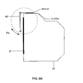
- FIGS. 6A , 6 B, 7 A, 7 B, 8 A and 8 B are side views of monitors and various camera supports for use herein.
- FIG. 9 depicts an image of a remote conferee on a monitor with an associated video camera as the image would appear in practicing the present invention.
- FIG. 2 Conferee 10 is ideally seated from 2 to 8 feet from video monitor 20 and particularly, its front face carrying image field 21 displaying the image of remotely located conferee 10 a .
- FIG. 2 shows camera 25 on or proximate to image field 21 at the eye level of conferees 10 and 10 A. Stated differently, video camera 25 is placed in front of monitor 20 within image field 21 whereby its optical axis coincides with the sight line 22 drawn between the eyes of the respective conferees.
- the camera's field of view is shown by phantom lines 22 A and 22 B and is adjusted and the conferees positioned so that the size of the facial image as it appears on the monitor at the remote location is approximately the same size as it would be if the conferee was attending a conference physically.
- placing camera 25 in front of the eyes of an image of the remote conferee with its optical axis coinciding with the sight line between conferees interferes with eye contact communication because the camera obscures regions of high emotional signal at and around the eyes.
- FIG. 3 For sake of direct comparison, common reference numerals are employed wherever possible while the depictions of local and remote conferees 10 and 10 A, the latter being displayed through video monitor 20 within image field 21 remains consistent as well.
- camera 25 instead of being located within image field 21 in front of the eyes of the video image of remote conferee 10 A is moved a distance above the eyes of conferee 10 A.
- the present invention contemplates locating video camera 25 directly within image field 21 facing conferee 10 and within an emotionally neutral field of conferee 10 A.
- Camera 25 is moved to an emotionally neutral field defined with respect to a portion of the face of remotely located conferee 10 A, as it appears over monitor 20 .
- repositioning camera 25 away from the eyes of the image of conferee 10 A to an emotionally neutral field of conferee 10 A restores the possibility for eye direct contact.
- the definition of an “emotionally neutral field” of the facial portion of a conferee will be discussed hereinafter. In the present discussion of FIG.
- camera 25 has been moved away from and above the eyes of the image of remotely located conferee 10 A in order to enable the conferees to engage in direct eye contact while substantially avoiding the creation of a significant parallax angle which would otherwise result in a conferee being sensed as looking downward from a remote location.
- camera 25 should be positioned above the eyes of conferee 10 A a distance which does not provide for a significant parallax angle and yet is not positioned directly in front of the eyes of conferee 10 A to enable each conferee to establish direct eye contact.
- ⁇ crit should be no greater than 3 degrees, although the actual value for ⁇ crit may be influenced by several variables including video resolution, video frame rate and lighting.
- FIG. 4 depicts the recited emotionally neutral field referred to previously.
- This field is defined by horizontal boundary lines 30 and 31 , the former being slightly above eye level and the latter at conferee 10 's hairline (or upper extremity of the forehead) while vertical lines 32 and 33 are defined by the outer extremities of the eyes of conferee 10 .
- a small object such as camera 25 located on or proximate image field 21 of video monitor 20 at emotionally neutral area 35 of the face of the image of remote conferee 10 A does not, in fact, produce an unacceptable obstruction.
- camera 25 In order to enhance the irrelevance of the obstruction created by the lens of camera 25 , it is preferable to provide camera 25 in the form of a cylindrical video camera having a small diameter. It was found that a “lipstick case” shaped camera having a diameter of 0.5 inches and a length of 2.5 inches clearly performed adequately in carrying out the present invention. Current technology has provided even smaller video cameras such as those used in invasive medical procedures such as in laparoscopy and colonoscopy which would provide even less intrusion.
- the prior art has taught to avoid placing the camera within image field 21 as, to do so, would interfere with the video conferencing experience, it has now been determined through the present invention that, when the camera is of a small dimension and placed in an emotionally neutral field of the image of the remote conferee, there is no unacceptable intrusion. Yet, the present invention promotes direct eye contact between conferees. As noted, such eye contact and facial expression is needed to promote a successful video conference as an excellent substitute to a face-to-face physical conference.
- FIG. 5 depicts camera “footprints” perpendicular to the optical axis, some of which are suitable for practicing the present invention while others are not.
- rectangular image 41 depicts the body of Sony's EV1-D30 camera which is widely used in traditional video conferencing systems. It features (1) pan-tilt-zoom to adjust the field of view, (2) focus control, and (3) an automatic iris.
- the cross section of this camera is too large for practicing the present invention for it substantially prevents eye contact when the camera is placed as suggested herein.
- Body “footprint” 41 of Sony's EV1-D30 has cross sectional dimensions perpendicular to the axis of viewing of 141 mm ⁇ 108 mm (5.6 in. ⁇ 4.2 in.). Such a camera is typically positioned on top of the monitor. If such a camera was to be centered as suggested, it would obstruct eye-to-eye contact.
- FIG. 5 further shows other camera “footprints” of decreasing size as viewed perpendicularly to each camera's optical axis.
- Rectangle 42 depicts the Polycom ViaVideo video conferencing camera. Again, this lens size mandates placement of the camera on top of the monitor.
- the typical video conferencing cameras like those shown as elements 41 and 42 requiring placement on top of the monitor results in a parallax angle between the camera's optical axis and the line established by direct eye to eye contact between conferees of from 8 to 15 degrees which is clearly larger than the critical angle necessary for practicing the present invention.
- Even lens 43 of Hitachi's KP-D8 video camera is marginally too large.
- “footprints” 44 , 45 and 46 representing Panasonic's GP-KS1000, Sony's DXC-LS1 and Toshiba's 1K-SM43H, respectively, can be employed in successfully practicing the present invention.
- the present invention contemplates using miniature cameras that have a lens “footprints” sufficiently small to enable conferees to establish eye-to-eye contact while not detracting from the conference experience.
- the present invention contemplates employing miniature cameras in which the lens “footprint” perpendicular to the camera's optical axis is no greater than 12 mm (0.47 in.) when used with a monitor having image field 21 with a diagonal dimension of 27 inches or greater.
- FIG. 9 depicts a side view and front view of a monitor showing the positioning of camera 25 within image field 21 and the effect that such positioning would have in establishing direct eye contact with remotely located conferee 10 A. It is noted that camera 25 is positioned within emotionally neutral field of conferee 10 A; in this instance, approximately at the middle of the forehead of the remotely located conferee. It is noted that camera 25 does not present an impediment in establishing facial contact with conferee 10 A while the positioning of camera 25 as shown enables the conferees to perceive direct eye contact during video conferencing.
- the positioning of the video camera often requires that it be tilted downward slightly and aimed at the subject's eyes as best depicted in FIG. 3 .
- the camera must also be panned to center the image.
- Camera support devices have been developed with the capabilities needed to carry out this repositioning and aiming. While the base of the camera's support assembly is designed to rest on the top of monitor 20 , such devices are intended to position the camera in front of the image of the remote video conferee within his or her emotionally neutral field 35 .
- a suction cup or a similar adhering device could be removeably retained upon image field 21 , the rubber body of which could capture a portion of camera 25 .
- a suction cup or a similar adhering device could be removeably retained upon image field 21 , the rubber body of which could capture a portion of camera 25 .
- the use of such a simplistic device would make it difficult to reposition camera 25 in the event that the conferee moved away from the camera's optical axis.
- the better solution would be to adopt commercially available devices for retaining suitable video cameras as described hereinafter.
- FIGS. 6A and 6B disclose the use of a manually operable support for adjustably positioning camera 25 in front of and proximate image field 21 of monitor 20 .
- Vertical adjustment of camera 25 is accomplished by moving vertical support arm 61 vis à vis horizontal support arm 62 which is in turn removeably positioned atop monitor 20 through the use of anchor 64 .
- Vertical support arm 61 is moved up or down by loosening lock screw 63 enabling vertical support arm 61 to move along slot 65 .
- Camera tilt is obtained by pivoting vertical support arm 61 on the axis of lock screw 63 .
- lock screw 63 can be tightened to prevent inadvertent movement.
- Manually rotating the anchor 64 about its vertical axis pans the camera 25 and will enable the user to adopt a desired horizontal field of view.
- Camera 25 can also be manipulated remotely by employing a device such as that depicted in FIGS. 7A and 7B .
- Camera 25 can be vertically moved using a remote control to signal a remote controller (not shown) for small DC electric motor 75 .
- Planetary gears reduce the rpm of the motor which is connected to shaft 77 which, in turn, is connected to pinion gear 74 .
- Rack 73 is made a part of vertical support arm 71 which supports camera 25 .
- Camera tilt is accomplished by using a suitable remote to control a signal directed to a tilt servo.
- the tilt servo drives tilt yoke 80 which is provided with a push-pull connection to horizontal support arm 72 .
- Horizontal support arm 72 pivots on a pin at the center of rotation shown as element 79 of FIG. 7A .
- the vertical support arm 71 is rigidly connected to the horizontal support arm 72 . Because of this rigid connection, tilting the horizontal support arm 72 with the tilt yoke 80 acts to tilt camera 25 . Further, camera 25 can be panned by using the remote control to signal pan servo 81 which, in turn, drives pan yoke 78 .
- Stage 80 is supported above base 76 on pan bearing 82 having a vertical axis of rotation.
- a push-pull connection between pan yoke 78 and stage 80 transfers pan yoke movements to stage movements. Since all active components are supported on base 76 , rotating the stage with the pan yoke pans camera 25 .
- FIGS. 8A and 8B can also be employed to adjust positioning of camera 25 noting that most of the hardware used to do so remains out of sight of the conferee.
- support system 90 is capable of providing remote, pan, tilt, up and down operation of camera 25 similar to that described with respect to FIGS. 7A and 7B .
- base 93 motor 91 , planetary gears 92 , pan yoke 94 and pan servo 95 all hidden from view
- the conferee sees only a 3 square inch component “footprint” in the embodiment shown in FIGS. 8A and 8B compared to a 10 square inch “footprint” for the embodiment shown in FIGS. 7A and 7B .
- FIG. 8A only vertical support arm 96 containing rack 97 and pinion 98 , support 99 and camera 25 remain visible.
Landscapes
- Engineering & Computer Science (AREA)
- Multimedia (AREA)
- Signal Processing (AREA)
- Two-Way Televisions, Distribution Of Moving Picture Or The Like (AREA)
Abstract
A method and device for video conferencing between first and second conference locations. Each conference location is provided with a video camera and a video image monitor to carry the image of a video conferee to a remote location. The video cameras are located proximate the video monitors such that each video camera is placed upon an emotionally neutral field of the image of the remotely located conferee and aimed substantially at the eyes of the local conferee facing the conferee's monitor in order to create eye-to-eye contact between conferees while positioning the video camera as to not interfere with said conference.
Description
The present invention is involved with a method and device for video conferencing between remote conference locations. The device consists of a video camera and image receiver, the image receiver being provided with a border and within the border, an image field for displaying the video image from the remote location. The video camera is mounted within the image field such as to promote eye-to-eye contact between conferees without camera intrusion.
Although video teleconferencing offers an attractive alternative to face-to-face meetings, its adoption has not been as pervasive as predicted. Certainly with the cost and inconvenience of air travel, being able to conduct conferences through electronic video conferencing provides a low cost and convenient alternative. However, the ergonomics inherent in video conferencing to date have limited its application.
It is well known that in addition to what is said at a meeting, emotional signals which are non-verbally communicated between parties can be very important. In the human body, muscle is the tissue that is specialized for the production of movement. Every muscle in the body connects to other structures via tendons, except in the human face. There, muscles connect directly to the skin. The musculature of the human face has evolved for a particular purpose, that is, to produce a variety of movements in the surface of the face, movements that are elements of a signaling system between human beings. The visible movements in the skin produced by facial muscles are called facial expressions. All human beings share an identical facial anatomy; they all have the same facial movements arranged in the same manner. Further, as demonstrated by various research practitioners, all human beings generate the same invariant group of facial expressions. In addition, all human beings are born with systems necessary to interpret those facial expressions.
Facial expressions therefore constitute an innate communication system, the evolutionary roots of which far predate spoken or written language. All written language is at most ten thousand years old, and spoken language a few hundred thousand years old. By contrast, the signaling system of which facial expressions are a part is approximately one hundred million years old. It is noted that specific areas of the human brain are dedicated to the processing of human facial expressions. Neural systems in the brain that decode facial expressions are significantly older than those responsible for conscious and voluntary behaviors. The decoding of facial expressions is part of an inherited neural architecture in the brain—it is invariant and involuntary.
The eyes are of particular importance in emotional signaling. Not only do the eyes contribute to the display of emotions such as fear or surprise, but human beings also use eye contact and the direction of gaze to communicate signals about the emotional context of an interaction. Eye contact and gaze direction impart information about the participants' perceptions of their relative social rank, personal power, trustworthiness, mutual liking, and assertiveness. Eye contact signals are also crucial in coordinating the exchange of speaking and listening roles, which occurs rapidly and fluently within normal conversational speech. Not surprisingly, research has demonstrated that human beings are highly proficient at making precise determinations about gaze direction in others. This function, as well as the decoding of complex signals inherent in eye contact, occurs on an involuntary basis.
Unfortunately, video teleconferencing involves an inherent lack of eye contact as part of the overall conferencing experience. Eye contact is not promoted by current terminal configurations because, generally, the video camera necessary to feed the video portion of the conference is placed either at the top or sides of the video monitor so as not to obstruct the image of the remotely located conferee. Typically, the camera is placed somewhere above the display monitor such as depicted in U.S. Pat. No. 5,900,907. If the conferee looks directly at the monitor in conversing with the remotely located conferee, the conferee is captured at an angle above the conferee's viewing level or head. Thus, when an image of that participant is displayed at the remote station, it appears as if the participant is looking down toward the ground. This can perhaps be best appreciated in viewing FIG. 1 whereby conferee 10 is shown looking directly into viewing area 21 as part of monitor 20. However, camera 22, perched above monitor 20 captures the face of conferee 10 at a parallax angle making it seem as if conferee 10 is looking down by that same angle to the counterpart of conferee 10 at the remote location. Without suitable eye contact, the potential of video conferencing is greatly reduced.
There has been a plethora of suggestions to correct the above-noted deficiency. For example, previously mentioned U.S. Pat. No. 5,900,907 suggests placing a camera atop the video monitor with a bracket and housing that enables the camera to extend below the top edge of the monitor and onto the upper region of the image field. However, such a configuration does not enable the camera lens to extend far enough within the image to reduce the parallax angle a sufficient amount to cure the problem. In addition, the camera housing clearly obstructs the image field and detracts from the video conferencing experience.
Others, such as is shown in U.S. Pat. No. 5,777,665, have used beam splitters, prisms and optical refraction devices enabling the camera to be placed outside the field of vision. However, these approaches require bulky equipment and are distracting in presenting a certain amount of visual obstruction. For example, U.S. Pat. No. 5,400,069 suggests the use of a half-silvered mirror as a projection screen with a camera placed behind the apparent location of the face of the remotely located conferee. Such devices are necessarily large and cumbersome. Moreover, because the conferee cannot see the camera filming the event, the conferee never actually looks at the camera, but merely in the general direction of the eyes of the remote conferee.
Another approach was suggested by U.S. Pat. No. 5,500,671. In this instance, it was suggested that computer software be employed to manipulate video images on the fly so that instead of an actual face, the viewer looks at a “virtual” face in which various facial features have been altered and reconstructed to simulate eye contact. This approach is obviously hardware and software intensive and is thus expensive to construct and employ and thus somewhat impractical.
As a fall back position in light of the seeming shortcomings of the prior art, the most common practice in the video conferencing industry today is to simply place the conferee at a remote distance from the camera and associated monitor in order to reduce the parallax angle. Although by doing so, the parallax angle is, in fact, reduced, this “solution” sacrifices the participants' ability to discern the details of each other's faces and encourages them to raise their voices to tiring levels in an unconscious reaction to the distance. Ideally, each conferee should be between 2 and 8 feet from the video monitor such that the size of the face of the remote conferee is “life-size.”
It is thus an object of the present invention to provide a method and apparatus for conducting video conferencing which avoids the problems associated with such prior art devices.
It is yet a further object of the present invention to provide a method and associated apparatus for conducting video conferencing which promotes eye contact between conferees without the need for engaging in complicated and expensive peripheral equipment in order to achieve this goal.
These and further objects will be more readily apparent when considering the following disclosure and appended claims.
The present invention is directed towards a method of video conferencing and apparatus useful in carrying out the recited method. Each remote conference location is provided with a video conferee, a video camera and an image monitor, wherein each monitor displays an image of the remote conferee. The video camera in each location is placed proximate its associated video monitor and is positioned at an emotionally neutral field of the image of the remote conferee as appearing upon the video monitor. Ideally, the optical axis of each video camera is aimed at the eyes of the conferee facing the video monitor at an angle that promotes the sense of direct eye contact between conferees.
In maximizing eye contact, reference is made to FIG. 2 . Conferee 10 is ideally seated from 2 to 8 feet from video monitor 20 and particularly, its front face carrying image field 21 displaying the image of remotely located conferee 10 a. To maximize direct eye contact, FIG. 2 , shows camera 25 on or proximate to image field 21 at the eye level of conferees 10 and 10A. Stated differently, video camera 25 is placed in front of monitor 20 within image field 21 whereby its optical axis coincides with the sight line 22 drawn between the eyes of the respective conferees. The camera's field of view is shown by phantom lines 22A and 22B and is adjusted and the conferees positioned so that the size of the facial image as it appears on the monitor at the remote location is approximately the same size as it would be if the conferee was attending a conference physically. However, as the prior art well recognized, placing camera 25 in front of the eyes of an image of the remote conferee with its optical axis coinciding with the sight line between conferees interferes with eye contact communication because the camera obscures regions of high emotional signal at and around the eyes.
The present invention can be appreciated by reference to FIG. 3 . For sake of direct comparison, common reference numerals are employed wherever possible while the depictions of local and remote conferees 10 and 10A, the latter being displayed through video monitor 20 within image field 21 remains consistent as well. However, in the present instance, camera 25, instead of being located within image field 21 in front of the eyes of the video image of remote conferee 10A is moved a distance above the eyes of conferee 10A. Unlike suggestions made by the prior art, the present invention contemplates locating video camera 25 directly within image field 21 facing conferee 10 and within an emotionally neutral field of conferee 10A.
It is quite apparent then that camera 25 should be positioned above the eyes of conferee 10A a distance which does not provide for a significant parallax angle and yet is not positioned directly in front of the eyes of conferee 10A to enable each conferee to establish direct eye contact. As such, it is of critical importance in practicing the present invention to limit the height to which camera 25 can be moved above eye-to-eye line of sight 22. It has now been determined that the lines of sight and the camera's optical axis will be perceived as being coincident resulting in perceived eye contact if the camera angle θ as shown in FIG. 3 is less than the critical camera angle for direct eye contact, θcrit. It has now been determined that θcrit should be no greater than 3 degrees, although the actual value for θcrit may be influenced by several variables including video resolution, video frame rate and lighting. In this regard, the camera angle θ, can be expressed as:
θ=(tan−1(H/D))
where
θ=(tan−1(H/D))
where
-
- θ=the angle between the camera's optical axis and the line of sight between the eyes of conferees.
- H=camera height above the sight line between the eyes of conferees.
- D=horizontal distance between the camera and the eyes of the conferee facing it.
Certainly, if θ is less than θcrit then direct eye contact is perceived between video conferees.
In order to enhance the irrelevance of the obstruction created by the lens of camera 25, it is preferable to provide camera 25 in the form of a cylindrical video camera having a small diameter. It was found that a “lipstick case” shaped camera having a diameter of 0.5 inches and a length of 2.5 inches clearly performed adequately in carrying out the present invention. Current technology has provided even smaller video cameras such as those used in invasive medical procedures such as in laparoscopy and colonoscopy which would provide even less intrusion. As such, although the prior art has taught to avoid placing the camera within image field 21 as, to do so, would interfere with the video conferencing experience, it has now been determined through the present invention that, when the camera is of a small dimension and placed in an emotionally neutral field of the image of the remote conferee, there is no unacceptable intrusion. Yet, the present invention promotes direct eye contact between conferees. As noted, such eye contact and facial expression is needed to promote a successful video conference as an excellent substitute to a face-to-face physical conference.
In light of the above noted discussion, not only is the camera position important, but camera intrusion upon the video conferencing experience is also influenced by the camera's size. FIG. 5 depicts camera “footprints” perpendicular to the optical axis, some of which are suitable for practicing the present invention while others are not. For example, rectangular image 41 depicts the body of Sony's EV1-D30 camera which is widely used in traditional video conferencing systems. It features (1) pan-tilt-zoom to adjust the field of view, (2) focus control, and (3) an automatic iris. The cross section of this camera, however, is too large for practicing the present invention for it substantially prevents eye contact when the camera is placed as suggested herein. Body “footprint” 41 of Sony's EV1-D30 has cross sectional dimensions perpendicular to the axis of viewing of 141 mm×108 mm (5.6 in.×4.2 in.). Such a camera is typically positioned on top of the monitor. If such a camera was to be centered as suggested, it would obstruct eye-to-eye contact.
As noted previously, the present invention contemplates using miniature cameras that have a lens “footprints” sufficiently small to enable conferees to establish eye-to-eye contact while not detracting from the conference experience. Ideally, the present invention contemplates employing miniature cameras in which the lens “footprint” perpendicular to the camera's optical axis is no greater than 12 mm (0.47 in.) when used with a monitor having image field 21 with a diagonal dimension of 27 inches or greater.
In practicing the present invention, the positioning of the video camera often requires that it be tilted downward slightly and aimed at the subject's eyes as best depicted in FIG. 3 . However, if the video conferee moves to one side, the camera must also be panned to center the image. Camera support devices have been developed with the capabilities needed to carry out this repositioning and aiming. While the base of the camera's support assembly is designed to rest on the top of monitor 20, such devices are intended to position the camera in front of the image of the remote video conferee within his or her emotionally neutral field 35.
There are many ways to support camera 25 on or in conjunction with image field 21. For example, a suction cup or a similar adhering device (not shown) could be removeably retained upon image field 21, the rubber body of which could capture a portion of camera 25. However, the use of such a simplistic device would make it difficult to reposition camera 25 in the event that the conferee moved away from the camera's optical axis. The better solution would be to adopt commercially available devices for retaining suitable video cameras as described hereinafter.
The embodiment shown in FIGS. 8A and 8B can also be employed to adjust positioning of camera 25 noting that most of the hardware used to do so remains out of sight of the conferee. As in the previous embodiment, support system 90 is capable of providing remote, pan, tilt, up and down operation of camera 25 similar to that described with respect to FIGS. 7A and 7B . However, with base 93, motor 91, planetary gears 92, pan yoke 94 and pan servo 95 all hidden from view, the conferee sees only a 3 square inch component “footprint” in the embodiment shown in FIGS. 8A and 8B compared to a 10 square inch “footprint” for the embodiment shown in FIGS. 7A and 7B . As noted in reference to FIG. 8A , only vertical support arm 96 containing rack 97 and pinion 98, support 99 and camera 25 remain visible.
Claims (14)
1. In a method of video conferencing between first and second conference locations, said first conference location having a first video conferee, a first video camera and first image monitor and said second conference location having a second video conferee, a second video camera and a second image monitor wherein said first video monitor displays an image of said second video conferee and said second video monitor displays an image of said first video conferee and, wherein said first and second video conferees face said first and second video cameras and first and second video monitors, respectively, the improvement comprising locating said first and second video cameras proximate said first and second image monitors, respectively, such that said first and second video cameras are aimed at said first and second video conferees, respectively, creating an angle between the optical axis of each of said video cameras and sight line established between the eyes of video conferees, said angle θ, defined by the equation:
θ=(tan−1(H/D))
θ=(tan−1(H/D))
wherein= H=camera height above the eye-to-eye sight line
D=horizontal distance of each camera to its conferee and wherein θ is ≦3 degrees.
2. The method of claim 1 wherein said video conferees are located between approximately 2 to 8 feet from each of conferee's video cameras.
3. The method of claim 2 wherein the video images of each first and second conferees as appearing upon said second and first video monitors at second and first conference locations, respectively, are approximately the size of said conferees.
4. The method of claim 1 wherein each of said first and second video cameras are characterized as having a length along its optical axis and a lens diameter perpendicular thereto.
5. The method of claim 4 wherein each of said first and second video cameras is characterized as having a lens diameter no greater than approximately 0.47 inches.
6. The method of claim 4 wherein each of said first and second video cameras is characterized as having a lens diameter no greater than approximately 0.28 inches.
7. The method of claim 1 wherein said first and second video and cameras are adjustably positionable upon said first and second video monitors such that said first video camera is adjustably maintained within said emotionally neutral field of the image of said second conferee appearing upon said first video monitor and is further adjustable to maintain its optical axis aimed at the eyes of said first video conferee and said second video camera is adjustably maintained within said emotionally neutral field of the image of said first conferee appearing upon said second video monitor and is further adjustable to maintain its optical axis aimed at the eyes of said second video conferee.
8. The method of claim 7 wherein said first and second video cameras are remotely adjustable at a distance from each camera location.
9. In a device for video conferencing between first and second conference locations, said first conference location having a first video conference, a first video camera and a first image monitor and said second conference location having a second video conferee, a second video camera and a second image monitor wherein said first video monitor displays an image of said second video conferee and said second video monitor displays an image of said first video conferee and wherein said first and second video conferees face said first and second video cameras and first and second video monitors, respectively, the improvement comprising positioning said first and second video cameras upon first and second monitors, respectively, such that said first video camera is place upon an emotionally neutral field of the image of said second video conferee and said second video camera is placed upon an emotionally neutral field of the image of said first video conferee and wherein said first and second video cameras are aimed at said first and second video conferees, respectively, creating an angle between the optical axis of each of said video cameras and sight line established between the eyes of video conferees, said angle θ, defined by the equation:
θ=(tan−1(H/D))
θ=(tan−1(H/D))
wherein= H=camera height above the eye-to-eye sight line between conferees
D=horizontal distance of each camera to its conferee and wherein θ≦3 degrees.
10. The device of claim 9 wherein said video conferees are located between approximately 2 to 8 feet from each of conferees video cameras.
11. The method of claim 10 wherein the video images of each first and second conferees as appearing upon the video monitors at said second and first conference locations, respectively, are approximately the size of said conferees.
12. The device of claim 9 wherein each of said first and second video cameras are characterized as having a length along its optical axis and a lens diameter perpendicular thereto.
13. The device of claim 12 wherein each of said first and second video cameras is characterized as having a lens diameter no greater than approximately 0.47 inches.
14. The device of claim 12 wherein each of said first and second video cameras is characterized as having a lens diameter no greater than approximately 0.28 inches.
Priority Applications (1)
| Application Number | Priority Date | Filing Date | Title |
|---|---|---|---|
| US10/092,667 US7126627B1 (en) | 2002-03-06 | 2002-03-06 | Video conferencing device and method |
Applications Claiming Priority (1)
| Application Number | Priority Date | Filing Date | Title |
|---|---|---|---|
| US10/092,667 US7126627B1 (en) | 2002-03-06 | 2002-03-06 | Video conferencing device and method |
Publications (1)
| Publication Number | Publication Date |
|---|---|
| US7126627B1 true US7126627B1 (en) | 2006-10-24 |
Family
ID=37110584
Family Applications (1)
| Application Number | Title | Priority Date | Filing Date |
|---|---|---|---|
| US10/092,667 Expired - Fee Related US7126627B1 (en) | 2002-03-06 | 2002-03-06 | Video conferencing device and method |
Country Status (1)
| Country | Link |
|---|---|
| US (1) | US7126627B1 (en) |
Cited By (45)
| Publication number | Priority date | Publication date | Assignee | Title |
|---|---|---|---|---|
| US20110063405A1 (en) * | 2009-09-17 | 2011-03-17 | Sony Corporation | Method and apparatus for minimizing acoustic echo in video conferencing |
| US20120274734A1 (en) * | 2011-04-28 | 2012-11-01 | Cisco Technology, Inc. | System and method for providing enhanced eye gaze in a video conferencing environment |
| US8472415B2 (en) | 2006-03-06 | 2013-06-25 | Cisco Technology, Inc. | Performance optimization with integrated mobility and MPLS |
| US8599865B2 (en) | 2010-10-26 | 2013-12-03 | Cisco Technology, Inc. | System and method for provisioning flows in a mobile network environment |
| US8599934B2 (en) | 2010-09-08 | 2013-12-03 | Cisco Technology, Inc. | System and method for skip coding during video conferencing in a network environment |
| US8659637B2 (en) | 2009-03-09 | 2014-02-25 | Cisco Technology, Inc. | System and method for providing three dimensional video conferencing in a network environment |
| US8659639B2 (en) | 2009-05-29 | 2014-02-25 | Cisco Technology, Inc. | System and method for extending communications between participants in a conferencing environment |
| US8682087B2 (en) | 2011-12-19 | 2014-03-25 | Cisco Technology, Inc. | System and method for depth-guided image filtering in a video conference environment |
| US8692862B2 (en) | 2011-02-28 | 2014-04-08 | Cisco Technology, Inc. | System and method for selection of video data in a video conference environment |
| US8694658B2 (en) | 2008-09-19 | 2014-04-08 | Cisco Technology, Inc. | System and method for enabling communication sessions in a network environment |
| US8699457B2 (en) | 2010-11-03 | 2014-04-15 | Cisco Technology, Inc. | System and method for managing flows in a mobile network environment |
| US8723914B2 (en) | 2010-11-19 | 2014-05-13 | Cisco Technology, Inc. | System and method for providing enhanced video processing in a network environment |
| US8730297B2 (en) | 2010-11-15 | 2014-05-20 | Cisco Technology, Inc. | System and method for providing camera functions in a video environment |
| US8786631B1 (en) | 2011-04-30 | 2014-07-22 | Cisco Technology, Inc. | System and method for transferring transparency information in a video environment |
| US8797377B2 (en) | 2008-02-14 | 2014-08-05 | Cisco Technology, Inc. | Method and system for videoconference configuration |
| US8804321B2 (en) | 2012-05-25 | 2014-08-12 | Steelcase, Inc. | Work and videoconference assembly |
| US8890919B2 (en) | 2012-02-29 | 2014-11-18 | Cisco Technology, Inc. | Video conferencing display and method to facilitate enhanced eye contact |
| US8896655B2 (en) | 2010-08-31 | 2014-11-25 | Cisco Technology, Inc. | System and method for providing depth adaptive video conferencing |
| US8902244B2 (en) | 2010-11-15 | 2014-12-02 | Cisco Technology, Inc. | System and method for providing enhanced graphics in a video environment |
| US20140362170A1 (en) * | 2012-02-15 | 2014-12-11 | Thomson Licensing | Video conference system and method for maintaining participant eye contact |
| US8934026B2 (en) | 2011-05-12 | 2015-01-13 | Cisco Technology, Inc. | System and method for video coding in a dynamic environment |
| US8947493B2 (en) | 2011-11-16 | 2015-02-03 | Cisco Technology, Inc. | System and method for alerting a participant in a video conference |
| US9082297B2 (en) | 2009-08-11 | 2015-07-14 | Cisco Technology, Inc. | System and method for verifying parameters in an audiovisual environment |
| US9111138B2 (en) | 2010-11-30 | 2015-08-18 | Cisco Technology, Inc. | System and method for gesture interface control |
| US9143725B2 (en) | 2010-11-15 | 2015-09-22 | Cisco Technology, Inc. | System and method for providing enhanced graphics in a video environment |
| US20150278989A1 (en) * | 2014-03-31 | 2015-10-01 | Electronics And Telecommunications Research Institute | Apparatus and method for controlling eye-to-eye contact function |
| US9225916B2 (en) | 2010-03-18 | 2015-12-29 | Cisco Technology, Inc. | System and method for enhancing video images in a conferencing environment |
| US9300916B1 (en) | 2015-02-10 | 2016-03-29 | International Business Machines Corporation | Natural gazes during online video conversations |
| US9313452B2 (en) | 2010-05-17 | 2016-04-12 | Cisco Technology, Inc. | System and method for providing retracting optics in a video conferencing environment |
| US9338394B2 (en) | 2010-11-15 | 2016-05-10 | Cisco Technology, Inc. | System and method for providing enhanced audio in a video environment |
| US20160182858A1 (en) * | 2014-12-17 | 2016-06-23 | Samsung Electronics Co., Ltd. | Multivision display apparatus |
| US9681154B2 (en) | 2012-12-06 | 2017-06-13 | Patent Capital Group | System and method for depth-guided filtering in a video conference environment |
| US9743040B1 (en) * | 2015-12-03 | 2017-08-22 | Symantec Corporation | Systems and methods for facilitating eye contact during video conferences |
| US9843621B2 (en) | 2013-05-17 | 2017-12-12 | Cisco Technology, Inc. | Calendaring activities based on communication processing |
| USD808197S1 (en) | 2016-04-15 | 2018-01-23 | Steelcase Inc. | Support for a table |
| USD838129S1 (en) | 2016-04-15 | 2019-01-15 | Steelcase Inc. | Worksurface for a conference table |
| US10219614B2 (en) | 2016-04-15 | 2019-03-05 | Steelcase Inc. | Reconfigurable conference table |
| WO2019064194A1 (en) * | 2017-09-26 | 2019-04-04 | Bansal Sanjay | System and method for providing a video conferencing setup |
| USD862127S1 (en) | 2016-04-15 | 2019-10-08 | Steelcase Inc. | Conference table |
| US10531050B1 (en) * | 2014-02-13 | 2020-01-07 | Steelcase Inc. | Inferred activity based conference enhancement method and system |
| US10560661B2 (en) | 2017-03-16 | 2020-02-11 | Dolby Laboratories Licensing Corporation | Detecting and mitigating audio-visual incongruence |
| US11174985B1 (en) * | 2020-05-24 | 2021-11-16 | Anastasios Michael Koulopoulos | Camera-positioning apparatuses and methods |
| US11381776B2 (en) * | 2020-08-27 | 2022-07-05 | Eye Contact Llc | Camera positioning device for eye-to-eye alignment in video conference applications |
| EP4090012A1 (en) | 2021-05-14 | 2022-11-16 | Commissariat à l'énergie atomique et aux énergies alternatives | Videoconferencing system for reducing a parallax effect associated with the direction of the gaze of a user |
| US12121150B2 (en) | 2022-01-31 | 2024-10-22 | Plexicam, Inc | Method and apparatus for dynamically mounting a camera in front of a display screen |
Citations (18)
| Publication number | Priority date | Publication date | Assignee | Title |
|---|---|---|---|---|
| US5117285A (en) | 1991-01-15 | 1992-05-26 | Bell Communications Research | Eye contact apparatus for video conferencing |
| US5317405A (en) | 1991-03-08 | 1994-05-31 | Nippon Telegraph And Telephone Corporation | Display and image capture apparatus which enables eye contact |
| US5400069A (en) | 1993-06-16 | 1995-03-21 | Bell Communications Research, Inc. | Eye contact video-conferencing system and screen |
| US5500671A (en) | 1994-10-25 | 1996-03-19 | At&T Corp. | Video conference system and method of providing parallax correction and a sense of presence |
| US5572248A (en) | 1994-09-19 | 1996-11-05 | Teleport Corporation | Teleconferencing method and system for providing face-to-face, non-animated teleconference environment |
| US5612733A (en) | 1994-07-18 | 1997-03-18 | C-Phone Corporation | Optics orienting arrangement for videoconferencing system |
| US5619254A (en) | 1995-04-11 | 1997-04-08 | Mcnelley; Steve H. | Compact teleconferencing eye contact terminal |
| US5666155A (en) | 1994-06-24 | 1997-09-09 | Lucent Technologies Inc. | Eye contact video telephony |
| US5777665A (en) | 1995-09-20 | 1998-07-07 | Videotronic Systems | Image blocking teleconferencing eye contact terminal |
| US5856842A (en) | 1996-08-26 | 1999-01-05 | Kaiser Optical Systems Corporation | Apparatus facilitating eye-contact video communications |
| US5953052A (en) | 1995-09-20 | 1999-09-14 | Videotronic Systems | Reflected display teleconferencing eye contact terminal |
| US6042235A (en) | 1996-11-08 | 2000-03-28 | Videotronic Systems | Videoconferencing eye contact spatial imaging display |
| US6208373B1 (en) | 1999-08-02 | 2001-03-27 | Timothy Lo Fong | Method and apparatus for enabling a videoconferencing participant to appear focused on camera to corresponding users |
| US6243130B1 (en) | 1995-09-20 | 2001-06-05 | Mcnelley Steve H. | Integrated reflected display teleconferencing eye contact terminal |
| US6326994B1 (en) * | 1997-01-22 | 2001-12-04 | Sony Corporation | Matched field-of-view stereographic imaging apparatus |
| US20030112325A1 (en) * | 2001-12-13 | 2003-06-19 | Digeo, Inc. | Camera positioning system and method for eye-to-eye communication |
| US6677980B1 (en) * | 1999-11-10 | 2004-01-13 | Jeon Byeung-Woo | Method and apparatus for correcting gaze of image using single camera |
| US6806847B2 (en) * | 1999-02-12 | 2004-10-19 | Fisher-Rosemount Systems Inc. | Portable computer in a process control environment |
-
2002
- 2002-03-06 US US10/092,667 patent/US7126627B1/en not_active Expired - Fee Related
Patent Citations (20)
| Publication number | Priority date | Publication date | Assignee | Title |
|---|---|---|---|---|
| US5117285A (en) | 1991-01-15 | 1992-05-26 | Bell Communications Research | Eye contact apparatus for video conferencing |
| US5317405A (en) | 1991-03-08 | 1994-05-31 | Nippon Telegraph And Telephone Corporation | Display and image capture apparatus which enables eye contact |
| US5400069A (en) | 1993-06-16 | 1995-03-21 | Bell Communications Research, Inc. | Eye contact video-conferencing system and screen |
| US5666155A (en) | 1994-06-24 | 1997-09-09 | Lucent Technologies Inc. | Eye contact video telephony |
| US5612733A (en) | 1994-07-18 | 1997-03-18 | C-Phone Corporation | Optics orienting arrangement for videoconferencing system |
| US6160573A (en) | 1994-09-19 | 2000-12-12 | Telesuite Corporation | Teleconference method and system for providing face-to-face teleconference environment |
| US5572248A (en) | 1994-09-19 | 1996-11-05 | Teleport Corporation | Teleconferencing method and system for providing face-to-face, non-animated teleconference environment |
| US5751337A (en) | 1994-09-19 | 1998-05-12 | Telesuite Corporation | Teleconferencing method and system for providing face-to-face, non-animated teleconference environment |
| US5500671A (en) | 1994-10-25 | 1996-03-19 | At&T Corp. | Video conference system and method of providing parallax correction and a sense of presence |
| US5619254A (en) | 1995-04-11 | 1997-04-08 | Mcnelley; Steve H. | Compact teleconferencing eye contact terminal |
| US6243130B1 (en) | 1995-09-20 | 2001-06-05 | Mcnelley Steve H. | Integrated reflected display teleconferencing eye contact terminal |
| US5953052A (en) | 1995-09-20 | 1999-09-14 | Videotronic Systems | Reflected display teleconferencing eye contact terminal |
| US5777665A (en) | 1995-09-20 | 1998-07-07 | Videotronic Systems | Image blocking teleconferencing eye contact terminal |
| US5856842A (en) | 1996-08-26 | 1999-01-05 | Kaiser Optical Systems Corporation | Apparatus facilitating eye-contact video communications |
| US6042235A (en) | 1996-11-08 | 2000-03-28 | Videotronic Systems | Videoconferencing eye contact spatial imaging display |
| US6326994B1 (en) * | 1997-01-22 | 2001-12-04 | Sony Corporation | Matched field-of-view stereographic imaging apparatus |
| US6806847B2 (en) * | 1999-02-12 | 2004-10-19 | Fisher-Rosemount Systems Inc. | Portable computer in a process control environment |
| US6208373B1 (en) | 1999-08-02 | 2001-03-27 | Timothy Lo Fong | Method and apparatus for enabling a videoconferencing participant to appear focused on camera to corresponding users |
| US6677980B1 (en) * | 1999-11-10 | 2004-01-13 | Jeon Byeung-Woo | Method and apparatus for correcting gaze of image using single camera |
| US20030112325A1 (en) * | 2001-12-13 | 2003-06-19 | Digeo, Inc. | Camera positioning system and method for eye-to-eye communication |
Cited By (65)
| Publication number | Priority date | Publication date | Assignee | Title |
|---|---|---|---|---|
| US8472415B2 (en) | 2006-03-06 | 2013-06-25 | Cisco Technology, Inc. | Performance optimization with integrated mobility and MPLS |
| US8797377B2 (en) | 2008-02-14 | 2014-08-05 | Cisco Technology, Inc. | Method and system for videoconference configuration |
| US8694658B2 (en) | 2008-09-19 | 2014-04-08 | Cisco Technology, Inc. | System and method for enabling communication sessions in a network environment |
| US8659637B2 (en) | 2009-03-09 | 2014-02-25 | Cisco Technology, Inc. | System and method for providing three dimensional video conferencing in a network environment |
| US9204096B2 (en) | 2009-05-29 | 2015-12-01 | Cisco Technology, Inc. | System and method for extending communications between participants in a conferencing environment |
| US8659639B2 (en) | 2009-05-29 | 2014-02-25 | Cisco Technology, Inc. | System and method for extending communications between participants in a conferencing environment |
| US9082297B2 (en) | 2009-08-11 | 2015-07-14 | Cisco Technology, Inc. | System and method for verifying parameters in an audiovisual environment |
| US8441515B2 (en) * | 2009-09-17 | 2013-05-14 | Sony Corporation | Method and apparatus for minimizing acoustic echo in video conferencing |
| US20110063405A1 (en) * | 2009-09-17 | 2011-03-17 | Sony Corporation | Method and apparatus for minimizing acoustic echo in video conferencing |
| US9225916B2 (en) | 2010-03-18 | 2015-12-29 | Cisco Technology, Inc. | System and method for enhancing video images in a conferencing environment |
| US9313452B2 (en) | 2010-05-17 | 2016-04-12 | Cisco Technology, Inc. | System and method for providing retracting optics in a video conferencing environment |
| US8896655B2 (en) | 2010-08-31 | 2014-11-25 | Cisco Technology, Inc. | System and method for providing depth adaptive video conferencing |
| US8599934B2 (en) | 2010-09-08 | 2013-12-03 | Cisco Technology, Inc. | System and method for skip coding during video conferencing in a network environment |
| US9331948B2 (en) | 2010-10-26 | 2016-05-03 | Cisco Technology, Inc. | System and method for provisioning flows in a mobile network environment |
| US8599865B2 (en) | 2010-10-26 | 2013-12-03 | Cisco Technology, Inc. | System and method for provisioning flows in a mobile network environment |
| US8699457B2 (en) | 2010-11-03 | 2014-04-15 | Cisco Technology, Inc. | System and method for managing flows in a mobile network environment |
| US8730297B2 (en) | 2010-11-15 | 2014-05-20 | Cisco Technology, Inc. | System and method for providing camera functions in a video environment |
| US9338394B2 (en) | 2010-11-15 | 2016-05-10 | Cisco Technology, Inc. | System and method for providing enhanced audio in a video environment |
| US8902244B2 (en) | 2010-11-15 | 2014-12-02 | Cisco Technology, Inc. | System and method for providing enhanced graphics in a video environment |
| US9143725B2 (en) | 2010-11-15 | 2015-09-22 | Cisco Technology, Inc. | System and method for providing enhanced graphics in a video environment |
| US8723914B2 (en) | 2010-11-19 | 2014-05-13 | Cisco Technology, Inc. | System and method for providing enhanced video processing in a network environment |
| US9111138B2 (en) | 2010-11-30 | 2015-08-18 | Cisco Technology, Inc. | System and method for gesture interface control |
| US8692862B2 (en) | 2011-02-28 | 2014-04-08 | Cisco Technology, Inc. | System and method for selection of video data in a video conference environment |
| US8670019B2 (en) * | 2011-04-28 | 2014-03-11 | Cisco Technology, Inc. | System and method for providing enhanced eye gaze in a video conferencing environment |
| US20120274734A1 (en) * | 2011-04-28 | 2012-11-01 | Cisco Technology, Inc. | System and method for providing enhanced eye gaze in a video conferencing environment |
| US8786631B1 (en) | 2011-04-30 | 2014-07-22 | Cisco Technology, Inc. | System and method for transferring transparency information in a video environment |
| US8934026B2 (en) | 2011-05-12 | 2015-01-13 | Cisco Technology, Inc. | System and method for video coding in a dynamic environment |
| US8947493B2 (en) | 2011-11-16 | 2015-02-03 | Cisco Technology, Inc. | System and method for alerting a participant in a video conference |
| US8682087B2 (en) | 2011-12-19 | 2014-03-25 | Cisco Technology, Inc. | System and method for depth-guided image filtering in a video conference environment |
| US20140362170A1 (en) * | 2012-02-15 | 2014-12-11 | Thomson Licensing | Video conference system and method for maintaining participant eye contact |
| US8890919B2 (en) | 2012-02-29 | 2014-11-18 | Cisco Technology, Inc. | Video conferencing display and method to facilitate enhanced eye contact |
| US10786074B2 (en) | 2012-05-25 | 2020-09-29 | Steelcase Inc. | Work and videoconference assembly |
| US8804321B2 (en) | 2012-05-25 | 2014-08-12 | Steelcase, Inc. | Work and videoconference assembly |
| US11612240B1 (en) | 2012-05-25 | 2023-03-28 | Steelcase Inc. | Work and videoconference assembly |
| US11185158B1 (en) | 2012-05-25 | 2021-11-30 | Steelcase Inc. | Work and videoconference assembly |
| US9681154B2 (en) | 2012-12-06 | 2017-06-13 | Patent Capital Group | System and method for depth-guided filtering in a video conference environment |
| US9843621B2 (en) | 2013-05-17 | 2017-12-12 | Cisco Technology, Inc. | Calendaring activities based on communication processing |
| US11706390B1 (en) | 2014-02-13 | 2023-07-18 | Steelcase Inc. | Inferred activity based conference enhancement method and system |
| US11006080B1 (en) | 2014-02-13 | 2021-05-11 | Steelcase Inc. | Inferred activity based conference enhancement method and system |
| US10531050B1 (en) * | 2014-02-13 | 2020-01-07 | Steelcase Inc. | Inferred activity based conference enhancement method and system |
| US10904490B1 (en) | 2014-02-13 | 2021-01-26 | Steelcase Inc. | Inferred activity based conference enhancement method and system |
| US12238458B1 (en) | 2014-02-13 | 2025-02-25 | Steelcase Inc. | Inferred activity based conference enhancement method and system |
| US9407871B2 (en) * | 2014-03-31 | 2016-08-02 | Electronics And Telecommunications Research Instit | Apparatus and method for controlling eye-to-eye contact function |
| US20150278989A1 (en) * | 2014-03-31 | 2015-10-01 | Electronics And Telecommunications Research Institute | Apparatus and method for controlling eye-to-eye contact function |
| US20160182858A1 (en) * | 2014-12-17 | 2016-06-23 | Samsung Electronics Co., Ltd. | Multivision display apparatus |
| US9626003B2 (en) | 2015-02-10 | 2017-04-18 | International Business Machines Corporation | Natural gazes during online video conversations |
| US9300916B1 (en) | 2015-02-10 | 2016-03-29 | International Business Machines Corporation | Natural gazes during online video conversations |
| US9743040B1 (en) * | 2015-12-03 | 2017-08-22 | Symantec Corporation | Systems and methods for facilitating eye contact during video conferences |
| US10219614B2 (en) | 2016-04-15 | 2019-03-05 | Steelcase Inc. | Reconfigurable conference table |
| USD808197S1 (en) | 2016-04-15 | 2018-01-23 | Steelcase Inc. | Support for a table |
| USD862127S1 (en) | 2016-04-15 | 2019-10-08 | Steelcase Inc. | Conference table |
| USD838129S1 (en) | 2016-04-15 | 2019-01-15 | Steelcase Inc. | Worksurface for a conference table |
| US10560661B2 (en) | 2017-03-16 | 2020-02-11 | Dolby Laboratories Licensing Corporation | Detecting and mitigating audio-visual incongruence |
| US11122239B2 (en) | 2017-03-16 | 2021-09-14 | Dolby Laboratories Licensing Corporation | Detecting and mitigating audio-visual incongruence |
| WO2019064194A1 (en) * | 2017-09-26 | 2019-04-04 | Bansal Sanjay | System and method for providing a video conferencing setup |
| US10939073B2 (en) | 2017-09-26 | 2021-03-02 | Sanjay Bansal | System and method for providing a video conferencing setup |
| US11174985B1 (en) * | 2020-05-24 | 2021-11-16 | Anastasios Michael Koulopoulos | Camera-positioning apparatuses and methods |
| US20240187550A1 (en) * | 2020-08-27 | 2024-06-06 | Cambox Inc. | Camera positioning device for eye-to-eye alignment in video conference applications |
| US11910127B2 (en) * | 2020-08-27 | 2024-02-20 | Cambox Inc. | Camera positioning device for eye-to-eye alignment in video conference applications |
| US20220286643A1 (en) * | 2020-08-27 | 2022-09-08 | Eye Contact Llc | Camera positioning device for eye-to-eye alignment in video conference applications |
| US12143750B2 (en) * | 2020-08-27 | 2024-11-12 | Cambox Inc. | Camera positioning device for eye-to-eye alignment in video conference applications |
| US11381776B2 (en) * | 2020-08-27 | 2022-07-05 | Eye Contact Llc | Camera positioning device for eye-to-eye alignment in video conference applications |
| FR3122938A1 (en) | 2021-05-14 | 2022-11-18 | Commissariat à l'Energie Atomique et aux Energies Alternatives | Videoconferencing system for reducing a parallax effect associated with the direction of a user's gaze |
| EP4090012A1 (en) | 2021-05-14 | 2022-11-16 | Commissariat à l'énergie atomique et aux énergies alternatives | Videoconferencing system for reducing a parallax effect associated with the direction of the gaze of a user |
| US12121150B2 (en) | 2022-01-31 | 2024-10-22 | Plexicam, Inc | Method and apparatus for dynamically mounting a camera in front of a display screen |
Similar Documents
| Publication | Publication Date | Title |
|---|---|---|
| US7126627B1 (en) | Video conferencing device and method | |
| US5438357A (en) | Image manipulating teleconferencing system | |
| US20230081404A1 (en) | Eye contact enabling device for video conferencing | |
| EP3358835B1 (en) | Improved method and system for video conferences with hmds | |
| US7388981B2 (en) | Telepresence system with automatic preservation of user head size | |
| US6208373B1 (en) | Method and apparatus for enabling a videoconferencing participant to appear focused on camera to corresponding users | |
| CA2157613C (en) | Video conference system and method of providing parallax correction and a sense of presence | |
| US6889120B2 (en) | Mutually-immersive mobile telepresence with gaze and eye contact preservation | |
| Otsuka | MMSpace: Kinetically-augmented telepresence for small group-to-group conversations | |
| US10802290B2 (en) | Display device assembly | |
| US20090201466A1 (en) | Goggles | |
| US20220407902A1 (en) | Method And Apparatus For Real-time Data Communication in Full-Presence Immersive Platforms | |
| TW202141120A (en) | Head wearable device with adjustable image sensing modules and its system | |
| US9088693B2 (en) | Providing direct eye contact videoconferencing | |
| CN113112407B (en) | Method, system, device and medium for generating field of view of television-based mirror | |
| CN108427195A (en) | A kind of information processing method and equipment based on augmented reality | |
| JP7532767B2 (en) | Shooting and display device, shooting and display system, and method for controlling shooting and display device | |
| JP3074679B2 (en) | Two-way interactive system | |
| JPH09327006A (en) | Two-way interactive system | |
| JP3074677B2 (en) | A two-way interactive system having a mechanism for matching eyes between interlocutors via transmission means | |
| US20250211457A1 (en) | Telepresence with a human avatar | |
| CN115079826B (en) | Virtual reality implementation method, electronic equipment and storage medium | |
| Gao et al. | Don't look at the camera: Achieving perceived eye contact in remote video communication | |
| JP3962881B2 (en) | Screen device | |
| CN112738309A (en) | Electronic equipment with double front lenses and shooting method |
Legal Events
| Date | Code | Title | Description |
|---|---|---|---|
| FPAY | Fee payment |
Year of fee payment: 4 |
|
| FPAY | Fee payment |
Year of fee payment: 8 |
|
| FEPP | Fee payment procedure |
Free format text: MAINTENANCE FEE REMINDER MAILED (ORIGINAL EVENT CODE: REM.) |
|
| LAPS | Lapse for failure to pay maintenance fees |
Free format text: PATENT EXPIRED FOR FAILURE TO PAY MAINTENANCE FEES (ORIGINAL EVENT CODE: EXP.); ENTITY STATUS OF PATENT OWNER: SMALL ENTITY |
|
| STCH | Information on status: patent discontinuation |
Free format text: PATENT EXPIRED DUE TO NONPAYMENT OF MAINTENANCE FEES UNDER 37 CFR 1.362 |
|
| FP | Lapsed due to failure to pay maintenance fee |
Effective date: 20181024 |