US7122926B2 - Fault-tolerant rotary actuator - Google Patents
Fault-tolerant rotary actuator Download PDFInfo
- Publication number
- US7122926B2 US7122926B2 US10/665,729 US66572903A US7122926B2 US 7122926 B2 US7122926 B2 US 7122926B2 US 66572903 A US66572903 A US 66572903A US 7122926 B2 US7122926 B2 US 7122926B2
- Authority
- US
- United States
- Prior art keywords
- prime mover
- rotary actuator
- output
- actuator
- clutch
- Prior art date
- Legal status (The legal status is an assumption and is not a legal conclusion. Google has not performed a legal analysis and makes no representation as to the accuracy of the status listed.)
- Expired - Lifetime
Links
Images


Classifications
-
- H—ELECTRICITY
- H02—GENERATION; CONVERSION OR DISTRIBUTION OF ELECTRIC POWER
- H02K—DYNAMO-ELECTRIC MACHINES
- H02K7/00—Arrangements for handling mechanical energy structurally associated with dynamo-electric machines, e.g. structural association with mechanical driving motors or auxiliary dynamo-electric machines
- H02K7/10—Structural association with clutches, brakes, gears, pulleys or mechanical starters
-
- H—ELECTRICITY
- H02—GENERATION; CONVERSION OR DISTRIBUTION OF ELECTRIC POWER
- H02K—DYNAMO-ELECTRIC MACHINES
- H02K16/00—Machines with more than one rotor or stator
-
- H—ELECTRICITY
- H02—GENERATION; CONVERSION OR DISTRIBUTION OF ELECTRIC POWER
- H02K—DYNAMO-ELECTRIC MACHINES
- H02K7/00—Arrangements for handling mechanical energy structurally associated with dynamo-electric machines, e.g. structural association with mechanical driving motors or auxiliary dynamo-electric machines
- H02K7/10—Structural association with clutches, brakes, gears, pulleys or mechanical starters
- H02K7/108—Structural association with clutches, brakes, gears, pulleys or mechanical starters with friction clutches
- H02K7/1085—Magnetically influenced friction clutches
-
- H—ELECTRICITY
- H02—GENERATION; CONVERSION OR DISTRIBUTION OF ELECTRIC POWER
- H02K—DYNAMO-ELECTRIC MACHINES
- H02K7/00—Arrangements for handling mechanical energy structurally associated with dynamo-electric machines, e.g. structural association with mechanical driving motors or auxiliary dynamo-electric machines
- H02K7/10—Structural association with clutches, brakes, gears, pulleys or mechanical starters
- H02K7/116—Structural association with clutches, brakes, gears, pulleys or mechanical starters with gears
-
- Y—GENERAL TAGGING OF NEW TECHNOLOGICAL DEVELOPMENTS; GENERAL TAGGING OF CROSS-SECTIONAL TECHNOLOGIES SPANNING OVER SEVERAL SECTIONS OF THE IPC; TECHNICAL SUBJECTS COVERED BY FORMER USPC CROSS-REFERENCE ART COLLECTIONS [XRACs] AND DIGESTS
- Y10—TECHNICAL SUBJECTS COVERED BY FORMER USPC
- Y10T—TECHNICAL SUBJECTS COVERED BY FORMER US CLASSIFICATION
- Y10T74/00—Machine element or mechanism
- Y10T74/20—Control lever and linkage systems
- Y10T74/20207—Multiple controlling elements for single controlled element
- Y10T74/20305—Robotic arm
- Y10T74/20317—Robotic arm including electric motor
Definitions
- the present invention relates generally to rotary actuators and more specifically to rotary actuators having improved fault-tolerance.
- Rotary actuators are the most common drivers of our machines.
- the partial or complete failure of an actuator can cause a life threatening accident, result in costly downtime, or prevent the continuation of a critical long-duration process, such as micro-surgery.
- a fault might occur, for example, in the electronics, wiring, sensors, prime mover, or gear train of the system.
- the present invention solves many problems associated with current fault-tolerant designs and overcomes problems associated with current approaches, development of redundant systems and output uncertainties.
- the present invention is a fully integrated actuator module, in a completely concentric arrangement in a single containment shell, containing two equal actuator subsystems that are either asymmetrically or symmetrically laid out. Both symmetric and asymmetric embodiments are described in detail herein.
- Fault tolerance in the actuators of the present invention is achieved by the employment of dual sets of equal resources.
- dual resources are integrated into single modules, with each having the external appearance and functionality of a single set of resources.
- the actuators employ a force-summing architecture wherein the dual output velocities are the same but the dual equal forces are summed to double the output load capacity. Should one side completely fail, then a clutch on that side would be disengaged to take that side out of action, leaving the other side to operate to return the system to home base in a ‘limp home’ mode, after which maintenance by module replacement can occur.
- the actuators employ a velocity-summing architecture wherein the velocities are summed, but the maximum torque output is limited to the torque output from each individual actuator.
- a clutch would be engaged on that side to lock that side in place and take that side out of action, leaving the other side to operate the system.
- the present invention is a rotary actuator having a fixed structure, with first and second prime movers attached to the fixed structure.
- the first prime mover has a first portion fixed to the fixed structure, and a second portion rotationally movable with respect to the first portion.
- the second prime mover has a first portion fixed to the fixed structure, and a second portion rotationally movable with respect to the first portion.
- the actuator incorporates a first gearset having an input portion connected to the second portion of the first prime mover and an output portion, as well as a second gearset having an input connected to the second portion of the second prime mover and an output portion.
- the actuator incorporates a first clutch having an input portion connected to the output portion of the first gearset and an output portion, and a second clutch having an input portion connected to the output portion of the second gearset and an output portion.
- the actuator incorporates dual equal outputs. A first actuator output is rotationally fixed to the output portion of the first clutch, and a second actuator output is rotationally fixed to the output portion of the second clutch.
- the present invention is a rotary actuator having a fixed structure having first and second prime movers attached thereto.
- the first prime mover has a first portion fixed to the fixed structure, and a second portion rotationally movable with respect to the first portion.
- the second prime mover also has a first portion fixed to the fixed structure, and a second portion rotationally movable with respect to the first portion.
- a first gearset has an input portion connected to the second portion of the first prime mover and an output portion.
- a second gearset has an input connected to the second portion of the second prime mover and an output portion.
- a first clutch has an input portion connected to the output portion of the first gearset and an output portion.
- a second clutch has an input portion connected to the output portion of the second gearset and an output portion.
- An actuator output is rotationally fixed to the output portion of the first clutch and the output portion of the second clutch.
- FIG. 1A is a three-dimensional section view of a first embodiment of a rotary actuator in accordance with the present invention
- FIG. 1B is a three-dimensional section view of the prime mover section of the rotary actuator of FIG. 1A ;
- FIG. 1C is a three-dimensional section view of the gear train section of the rotary actuator of FIG. 1A ;
- FIG. 1D is a three-dimensional section view of the output section of the rotary actuator of FIG. 1A ;
- FIG. 2A is a three-dimensional section view of a second embodiment of a rotary actuator in accordance with the present invention.
- FIG. 2B is a three-dimensional section view of the first prime mover section of the rotary actuator of FIG. 2A ;
- FIG. 2C is a three-dimensional section view of the second prime mover section of the rotary actuator of FIG. 2A ;
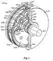
- FIG. 3 is another view of a rotary actuator in accordance with the present invention.
- FIG. 1A is a three-dimensional section view of a first embodiment of a rotary actuator 100 in accordance with the present invention.
- FIG. 1B is a three-dimensional section view of the prime mover section of the rotary actuator 100 of FIG. 1 A.
- FIG. 1C is a three-dimensional section view of a representative gear train section of the rotary actuator 100 of FIG. 1 A.
- FIG. 1D is a three-dimensional section view of the output section of the rotary actuator 100 of FIG. 1 A.
- duality is achieved by summing the equal prime mover forces against output plate 106 through a pair of geared transmissions.
- Prime mover 110 drives gear train 104 to create a torque on the output attachment plate through clutch 114 .
- prime mover 102 drives gear train 112 to create a torque on the output attachment plate 106 through clutch 108 .
- clutch 108 would be energized to take that subsystem out of service. In this case, the remaining subsystem would either carry 50% of the required output, which may be entirely adequate for most operations, or it could be peaked up past its normal performance level for a short period until the system could be taken down for maintenance.
- prime movers 102 and 110 exhibit substantially identical performance characteristics. In other words, prime movers 102 and 110 are able to generate substantially identical torque output, and operate across a similar range of speeds.
- Output plate 106 contains a torque sensor 116 .
- Output plate 106 is separated from the input attachment 118 by principal bearing 120 .
- output plate 106 is connected to the input drive systems by clutches 108 and 114 .
- Clutch 114 is driven by sun gear 122 , supported by bearings 124 and bull gear 126 .
- Bull gear 126 is meshed with planet gear set 128 supported by bearings 124 and held in place by planet cage 132 .
- Planet cage 132 is driven by armature 134 and supported by bearings 136 .
- the fixed motor field 138 operates on armature 134 .
- Fields 138 and 140 are fixed to the rigid fixed structure 142 attached to the outer shell 146 of the actuator 100 through end cap screws 144 .
- Rigid fixed structure 142 also employs screws 148 to fix the stationary shaft 150 , which supports bearings 152 for armature 154 .
- Armature 154 is also supported by bearing 156 and planet cage 158 , using bearings 160 to support planet gear set 162 .
- Planet gear set 162 meshes with the stationary bull gear 164 and sun gear 166 , supported by bearings 170 .
- Sun gear 166 then drives the output plate 106 through clutch 108 .
- Auxiliary bearing 172 gives further support to the output plate 106 from the stationary shaft 150 .
- a similar set of auxiliary bearings 174 are used to provide mutual support between the planet gear cages 158 and 132 . The result is that two prime mover-transmission subsystems create independent torques on output plate 106 through clutches 108 and 114 .
- This system incorporates no single point failure, since it can still operate even under a total, or partial, failure of 50% of the actuator's resources.
- This system can be described as being reconfigurable in the level of force to be supplied by each prime mover to the output. Where force balancing between the two equal subsystems may be achieved in real time, this actuator may perform at an even higher level of performance.
- Actuator 100 employs a certain geartrain architecture, but it will be understood by those of skill in the art that a number of geartrain geometries and architectures would be operable in the present invention without departing from the spirit and scope of the present invention. Additionally, while actuator 100 employs a pair of fixed fields and rotating armatures in concentric arrangement, nothing within the spirit and scope of the present invention requires this geometry. In alternate embodiments, the armatures could be fixed, or could be disposed adjacent to the fields in a pancake arrangement.
- Actuator 100 described above provides a high level of performance in a short, space-efficient package having a relatively small outer diameter. Certain rotary actuator applications may occur where there is a need for the diameter of the actuator to be minimized while the length of the actuator is not critical. This is the case, for example, for trim tabs for water vanes on ships or ailerons on aircraft.
- FIG. 2A is a three-dimensional section view of a second embodiment of a rotary actuator 200 having a symmetrical geometry in accordance with the present invention.
- FIG. 2B is a three-dimensional section view of the first prime mover and gear train section of the rotary actuator 200 of FIG. 2 A.
- FIG. 2C is a three-dimensional section view of the second prime mover and gear train section of the rotary actuator 200 of FIG. 2 A.
- FIGS. 2A-2C provide a detailed graphical representation of a dual symmetric torque summing fault tolerant rotary actuator 200 .
- FIG. 2A shows the general layout of rotary actuator 200 wherein two prime movers each drive a gear train, each of which drives an output attachment plate through a torque sensor and a clutch.
- planet gear cages 210 and 212 are supported by needle bearings 214 and 216 , and carry planet gear sets 218 and 220 in bearings 222 and 224 on shafts 226 and 228 .
- the planet gear sets 218 and 220 mesh with the stationary bull gears 230 and 232 and rotating sun gears 234 and 236 .
- the bull gears 230 and 232 are rigidly attached to the outer shells 238 and 240 of the actuator 200 .
- the sun gears 234 and 236 are rigidly attached to the output attachment plates 242 and 244 .
- the bull gears 230 and 232 and sun gears 234 and 236 are separated by the principal bearings 246 and 248 , which also act as the bearings of the joint of which this actuator 200 is a part.
- the output attachment plates 242 and 244 incorporate torque sensors 250 and 252 and release clutches 254 and 256 .
- the shell is assembled in two halves using assembly screws 258 with a fixed structure 260 in the center that also holds the centering shaft 266 of the actuator 200 , holding support bearings 262 and 264 .
- the output attachments shown are configured for yokes. Other geometries are possible wherein attachments are molded into the shell or as axial extensions to the face of the output plates. This latter arrangement would make the assembly longer and slimmer, which is useful as an actuator for a water vane trim tab for a ship or an aileron for an airplane.
- the yoke arrangement shown would be useful as an elbow in a robot manipulator or similar device.
- FIG. 3 A third embodiment of a rotary actuator 300 according to the present invention is shown in FIG. 3 .
- the central axis of actuator 300 is the center line of the output shaft 302 .
- the two independent prime movers are permanent magnet disks 304 and 306 that rotate about the center line supported by bearings 308 and 310 supported directly by the actuator shell 312 .
- the stationary magnetic fields 314 are rigidly held by the outer walls of the actuator 300 and are independently controlled by a power supply module.
- actuator 300 may employ a power supply module provided by Silicon Power Corporation of Eaton, Pa. Another suitable power supply module is manufactured by ARM Automation, Inc. of Austin, Tex.
- Each of the prime mover magnet disks 304 and 306 drives a radial gear 316 , which is meshed with differential gears 318 supported by bearings 320 and 322 in cage 324 , which rotates about the major center line of the actuator module 300 .
- the differential gears 318 will be stationary relative to magnet disks 304 and 306 if they rotate at the same speed, or produce the same torque. Otherwise, just as in an automobile drive train, the differential gears 318 will rotate to accommodate this difference in velocity.
- Cage 324 contains the planet gears 326 and 328 , which are rigidly connected to each other and supported on the ends by bearing 10 all held by the cage 324 .
- Cage 324 is the central structural element in actuator 300 .
- the section holding the race for bearing 330 and bearings 332 is assembled from machined sections. There may be four differential gears and up to eight planetary gears 326 and 328 held by the cage 324 which is supported by bearings 334 as well as bearing 330 .
- the planet gears 328 drive a sun gear 336 , which is machined into shaft 302 .
- Planet gears 326 roll over a stationary bull gear 338 .
- This stationary bull gear 338 is rigidly bolted to the actuator shell 312 with benefit of a centering boss to accurately locate it on the main center line of actuator 300 .
Landscapes
- Engineering & Computer Science (AREA)
- Power Engineering (AREA)
- Retarders (AREA)
- Gear-Shifting Mechanisms (AREA)
Abstract
Description
Claims (22)
Priority Applications (1)
| Application Number | Priority Date | Filing Date | Title |
|---|---|---|---|
| US10/665,729 US7122926B2 (en) | 2002-09-19 | 2003-09-18 | Fault-tolerant rotary actuator |
Applications Claiming Priority (2)
| Application Number | Priority Date | Filing Date | Title |
|---|---|---|---|
| US41197902P | 2002-09-19 | 2002-09-19 | |
| US10/665,729 US7122926B2 (en) | 2002-09-19 | 2003-09-18 | Fault-tolerant rotary actuator |
Publications (2)
| Publication Number | Publication Date |
|---|---|
| US20040103742A1 US20040103742A1 (en) | 2004-06-03 |
| US7122926B2 true US7122926B2 (en) | 2006-10-17 |
Family
ID=32030771
Family Applications (1)
| Application Number | Title | Priority Date | Filing Date |
|---|---|---|---|
| US10/665,729 Expired - Lifetime US7122926B2 (en) | 2002-09-19 | 2003-09-18 | Fault-tolerant rotary actuator |
Country Status (3)
| Country | Link |
|---|---|
| US (1) | US7122926B2 (en) |
| AU (1) | AU2003267206A1 (en) |
| WO (1) | WO2004027266A2 (en) |
Cited By (16)
| Publication number | Priority date | Publication date | Assignee | Title |
|---|---|---|---|---|
| US20060113933A1 (en) * | 2004-06-04 | 2006-06-01 | The Boeing Company | Fault-tolerant electromechanical actuator having a torque sensing control system |
| US20140060223A1 (en) * | 2011-06-03 | 2014-03-06 | Sony Corporation | Actuator device, multi-shaft driving device, and robot device |
| US9365105B2 (en) | 2013-10-11 | 2016-06-14 | Delbert Tesar | Gear train and clutch designs for multi-speed hub drives |
| US9657813B2 (en) | 2014-06-06 | 2017-05-23 | Delbert Tesar | Modified parallel eccentric rotary actuator |
| US9862263B2 (en) | 2013-03-01 | 2018-01-09 | Delbert Tesar | Multi-speed hub drive wheels |
| US9879760B2 (en) | 2002-11-25 | 2018-01-30 | Delbert Tesar | Rotary actuator with shortest force path configuration |
| US9915319B2 (en) | 2014-09-29 | 2018-03-13 | Delbert Tesar | Compact parallel eccentric rotary actuator |
| US10414271B2 (en) | 2013-03-01 | 2019-09-17 | Delbert Tesar | Multi-speed hub drive wheels |
| US10422387B2 (en) | 2014-05-16 | 2019-09-24 | Delbert Tesar | Quick change interface for low complexity rotary actuator |
| US10464413B2 (en) | 2016-06-24 | 2019-11-05 | Delbert Tesar | Electric multi-speed hub drive wheels |
| US11014658B1 (en) | 2015-01-02 | 2021-05-25 | Delbert Tesar | Driveline architecture for rotorcraft featuring active response actuators |
| US11022200B2 (en) | 2014-06-06 | 2021-06-01 | Delbert Tesar | Simplified parallel eccentric rotary actuator |
| WO2021174080A1 (en) | 2020-02-28 | 2021-09-02 | Moog Inc. | Fault tolerant multiple rotary actuator assembly |
| US11166864B2 (en) | 2016-12-06 | 2021-11-09 | Delbert Tesar | Actuators for patient mobility devices, patient healthcare devices and human prosthetics |
| US12330771B2 (en) | 2023-10-31 | 2025-06-17 | Honeywell International Inc. | Differential lock actuator systems and methods for moving flight control surface |
| US12504057B2 (en) | 2023-01-10 | 2025-12-23 | Goodrich Actuation Systems Sas | Epicyclic gear system |
Families Citing this family (12)
| Publication number | Priority date | Publication date | Assignee | Title |
|---|---|---|---|---|
| GB0027709D0 (en) * | 2000-11-14 | 2000-12-27 | Univ Coventry | Roller screw |
| US20070168081A1 (en) * | 2005-05-06 | 2007-07-19 | Sung-Ho Shin | Analytic integration of tolerances in designing precision interfaces for modular robotics |
| DE102005030218A1 (en) * | 2005-06-29 | 2007-01-25 | Robert Bosch Gmbh | Adapter and method for connecting an electric motor to a transmission interface of a body part |
| US8219245B2 (en) * | 2006-05-15 | 2012-07-10 | Kuka Roboter Gmbh | Articulated arm robot |
| US8843218B2 (en) * | 2011-07-22 | 2014-09-23 | GM Global Technology Operations LLC | Method and system for limited time fault tolerant control of actuators based on pre-computed values |
| CN104203505A (en) * | 2012-03-22 | 2014-12-10 | 株式会社安川电机 | Work robot and robot system |
| EP3020632B1 (en) | 2014-11-13 | 2018-12-26 | Safran Landing Systems UK Limited | Aircraft landing gear assembly |
| BR112018014266A2 (en) * | 2016-01-13 | 2018-12-18 | Moog Inc | rotary actuator assembly |
| US10253855B2 (en) | 2016-12-15 | 2019-04-09 | Boston Dynamics, Inc. | Screw actuator for a legged robot |
| DE102017209174A1 (en) * | 2017-05-31 | 2018-12-06 | Siemens Aktiengesellschaft | Redundant electric machine for driving a propulsion means |
| US11060593B2 (en) * | 2018-10-19 | 2021-07-13 | Hamilton Sundstrand Corporation | Jam-tolerant electric rotary actuator |
| CN109687671B (en) * | 2019-03-04 | 2020-06-16 | 哈尔滨工业大学 | Axial Parallel Double Stator Multiphase Permanent Magnet Fault Tolerant Motor |
Citations (114)
| Publication number | Priority date | Publication date | Assignee | Title |
|---|---|---|---|---|
| US276776A (en) | 1883-05-01 | Apparatus for transmitting differential rotary motion | ||
| US474903A (en) | 1892-05-17 | George cottrell | ||
| US546249A (en) | 1895-09-10 | Power-transmitter | ||
| US908529A (en) | 1907-05-22 | 1909-01-05 | Harvey D Williams | Power-transmission gearing. |
| US978371A (en) | 1910-02-18 | 1910-12-13 | William L Harrison | Mechanism for transmitting rotary motion. |
| US987430A (en) | 1911-03-21 | William C Conant | Speed-changing mechanism. | |
| US1009954A (en) | 1908-07-28 | 1911-11-28 | Jose Luis De Briones | Speed-changing mechanism. |
| US1192627A (en) | 1915-12-09 | 1916-07-25 | David H Hatlee | Speed-reducer. |
| US1217427A (en) | 1915-05-18 | 1917-02-27 | Gustave Fast | Gearing. |
| US1282172A (en) | 1916-04-26 | 1918-10-22 | John A Beirns | Electric starter. |
| US1313537A (en) | 1919-08-19 | George jones | ||
| US1499763A (en) | 1922-04-15 | 1924-07-01 | Rembrandt Peale | Power-transmitting and speed-reducing mechanism |
| US1514938A (en) | 1923-02-07 | 1924-11-11 | Gen Motors Corp | Connecting gearing |
| US1590166A (en) | 1923-02-14 | 1926-06-22 | Jesse C Howard | Speed-reducing device for pumps |
| US1601750A (en) | 1923-11-02 | 1926-10-05 | Wildhaber Ernest | Helical gearing |
| US1641766A (en) | 1925-01-24 | 1927-09-06 | Laukhuff Alfred | Speed reducer |
| US1693154A (en) | 1927-03-16 | 1928-11-27 | Newmann John | Transmission mechanism |
| US1694031A (en) | 1925-12-05 | 1928-12-04 | Matthew M Looram | Motion-picture camera |
| US1735662A (en) | 1928-01-09 | 1929-11-12 | Trevino Manuel Falcon | Miniature aeroplane |
| US1767866A (en) | 1927-11-10 | 1930-06-24 | Wildhaber Ernest | Gearing |
| US1770035A (en) | 1927-09-09 | 1930-07-08 | Heap Walter | Speed-reduction gearing |
| US1831903A (en) | 1928-06-21 | 1931-11-17 | Pittsburgh Equitable Meter Co | Reduction gearing |
| US1844471A (en) | 1928-01-10 | 1932-02-09 | J P Johnson Engineering Compan | Coupling |
| US1942795A (en) | 1931-02-05 | 1934-01-09 | Melvin B Benson Corp | Power transmission and speed reduction system |
| US2026880A (en) | 1932-07-09 | 1936-01-07 | Fliesberg | Transmission gear |
| US2037787A (en) | 1932-10-20 | 1936-04-21 | Chrysler Corp | Power transmission mechanism |
| US2049696A (en) | 1935-03-07 | 1936-08-04 | Erhard A M Fliesberg | Transmission gear |
| US2108384A (en) | 1936-11-19 | 1938-02-15 | Moisy Alexandre | Transmission gear for electric starters |
| US2168164A (en) | 1937-11-06 | 1939-08-01 | John W Kittredge | Speed reducer |
| US2170951A (en) | 1937-12-06 | 1939-08-29 | Fred W Coffing | Continuous power eccentric dual gear speed reducer |
| US2250259A (en) | 1940-03-11 | 1941-07-22 | Jr Bradford Foote | Speed reducing gearing |
| US2303365A (en) | 1939-11-14 | 1942-12-01 | Karlsen Karl Henry | Clock mechanism |
| US2382482A (en) | 1944-02-14 | 1945-08-14 | Erwin W Henry | Speed reduction gear |
| US2408993A (en) * | 1944-05-16 | 1946-10-08 | Bendix Aviat Corp | Actuator unit for retractable landing gears |
| US2475504A (en) | 1945-03-10 | 1949-07-05 | Jackson Jesse Atwater | Reduction gear |
| US2481627A (en) | 1946-01-24 | 1949-09-13 | Franklin Inst Of The State Of | Transmission unit |
| US2482568A (en) | 1945-05-26 | 1949-09-20 | Gen Motors Corp | Actuator control |
| US2495811A (en) | 1948-05-26 | 1950-01-31 | Hubert Q Hollmann | Hoist |
| US2666336A (en) | 1950-06-10 | 1954-01-19 | Hill Myron Francis | Internal gear teeth |
| US2677288A (en) | 1951-07-06 | 1954-05-04 | Gnahrich Alfred | Speed reducing transmission mechanism |
| US2709929A (en) | 1953-01-22 | 1955-06-07 | Clifford B Godwin | Sinusoidal planetary coupling mechanism |
| US2748616A (en) | 1952-03-12 | 1956-06-05 | Tmm Research Ltd | Drive mechanism for textile combing machines |
| US2837937A (en) | 1954-10-22 | 1958-06-10 | Excelermatic | Speed changer |
| US2881619A (en) | 1957-04-23 | 1959-04-14 | Richard J Fox | Coaxial control rod drive mechanism for neutronic reactors |
| US2922294A (en) | 1956-05-07 | 1960-01-26 | Wildhaber Ernest | Toothed couplings |
| US2966078A (en) | 1958-01-29 | 1960-12-27 | Richards Structural Steel Co L | Driving means for conveyors |
| US2972910A (en) | 1958-06-06 | 1961-02-28 | Abury H Temple | Speed reducer |
| US3011304A (en) | 1957-04-15 | 1961-12-05 | Edward V Sundt | Clockwork mechanism |
| US3019705A (en) | 1957-12-13 | 1962-02-06 | American Optical Corp | Coarse and fine adjustment mechanism for microscopes |
| US3028513A (en) | 1959-07-29 | 1962-04-03 | Edward V Sundt | Motorized dial control mechanism |
| US3037400A (en) | 1959-01-14 | 1962-06-05 | Edward V Sundt | Differential gear reducer |
| US3056315A (en) | 1959-01-06 | 1962-10-02 | Albert A Mros | Reduction gear drive unit |
| US3144791A (en) | 1958-06-06 | 1964-08-18 | Aubry H Temple | Speed reducer |
| US3160032A (en) | 1961-05-25 | 1964-12-08 | Black Tool Inc | Epicyclic speed changing device and gear form therefor |
| US3192799A (en) | 1962-08-13 | 1965-07-06 | Huska Paul | Transmission drive elements |
| US3307434A (en) | 1964-06-22 | 1967-03-07 | David G Kope | Speed reducing mechanism |
| US3413896A (en) | 1967-05-22 | 1968-12-03 | Wildhaber Ernest | Planetary motion mechanism |
| US3424036A (en) | 1967-01-17 | 1969-01-28 | Rex Chainbelt Inc | Speed changing device |
| US3427901A (en) | 1966-10-14 | 1969-02-18 | Ernest Wildhaber | Gearing |
| US3429393A (en) | 1966-12-08 | 1969-02-25 | Lorence Mfg Corp | Drive mechanism |
| US3451290A (en) | 1967-04-03 | 1969-06-24 | Ernest Wildhaber | Gear drive with axially overlapping gears |
| US3546972A (en) | 1967-08-30 | 1970-12-15 | Muneharu Morozumi | Profile shifted involute internal gearing |
| US3766790A (en) | 1971-12-29 | 1973-10-23 | Boeing Co | Non-jamming ball screw linear actuator |
| US3903750A (en) | 1972-11-18 | 1975-09-09 | Toyo Glass Machinery Co Ltd | Speed reduction mechanism |
| US3924478A (en) | 1972-11-18 | 1975-12-09 | Toyo Glass Machinery Company L | Speed reduction mechanism |
| US3975973A (en) | 1973-04-17 | 1976-08-24 | Haase Charles A | In-drum drive and speed reducer |
| US4016780A (en) | 1975-03-03 | 1977-04-12 | Trochoidal Gear Technology, Inc. | Hypotrochoidal cluster gear drives |
| US4023441A (en) | 1974-11-15 | 1977-05-17 | Osterwalder Jean Pierre F | Speed reducing device |
| US4155276A (en) | 1977-03-28 | 1979-05-22 | Fengler Werner H | High-ratio speed-reduction transmission |
| US4243355A (en) | 1979-09-24 | 1981-01-06 | Brudi Equipment Co., Inc. | Lift truck rotator with pressure-relieved valving |
| US4270401A (en) | 1977-09-16 | 1981-06-02 | Robert Davidson | Gear teeth |
| US4452102A (en) | 1981-04-23 | 1984-06-05 | New Age Industries, Inc. | Epicycloidal gearing |
| US4512213A (en) | 1981-10-30 | 1985-04-23 | Newton Alan R | Speed reducer |
| US4603594A (en) | 1984-05-31 | 1986-08-05 | Sundstrand Corporation | Fail safe actuator |
| US4614128A (en) | 1981-12-18 | 1986-09-30 | Lars International S.A., Luxembourg | Linear drive device with two motors |
| US4679485A (en) | 1984-12-27 | 1987-07-14 | Sundstrand Corporation | Ballistic tolerant dual load path ballscrew and ballscrew actuator |
| US4745815A (en) | 1986-12-08 | 1988-05-24 | Sundstrand Corporation | Non-jamming screw actuator system |
| US5030184A (en) | 1987-01-26 | 1991-07-09 | Gustav Rennerfelt | Eccentric gear |
| US5039900A (en) | 1989-02-15 | 1991-08-13 | Kabushiki Kaisha Okuma Tekkosho | Braking device for a rotary motor including a compression spring and piezoelectric element |
| US5136201A (en) | 1990-04-27 | 1992-08-04 | Rockwell International Corporation | Piezoelectric robotic articulation |
| US5144851A (en) | 1991-08-01 | 1992-09-08 | Sundstrand Corp. | Jam tolerant linear actuator |
| US5214972A (en) | 1992-04-30 | 1993-06-01 | Alliedsignal Aerospace | Fault-tolerant linear electromechanical actuator |
| US5232412A (en) | 1989-07-11 | 1993-08-03 | Yue Zheng | High efficiency gear transmission |
| US5277672A (en) | 1989-06-30 | 1994-01-11 | Ets. Cousin Freres | Clearance take up device for so-called continuous epicycloidal train articulations, and its mounting mode |
| US5295925A (en) | 1991-11-22 | 1994-03-22 | Harmonic Drive Systems, Inc. | Planetary gear transmission |
| US5313852A (en) | 1992-11-06 | 1994-05-24 | Grumman Aerospace Corporation | Differential linear actuator |
| US5324240A (en) | 1992-01-10 | 1994-06-28 | Aginfor Ag Fur Industrielle Forschung | Eccentric gear system |
| US5505668A (en) | 1994-07-29 | 1996-04-09 | Ikona Gears Limited | Gear system |
| GB2271025B (en) | 1992-09-26 | 1996-11-20 | Pitt Steele Ian Broderick | Electric motor |
| US5633554A (en) | 1992-05-29 | 1997-05-27 | Sumitomo Heavy Industries, Ltd. | Piezoelectric linear actuator |
| US5685694A (en) | 1995-11-07 | 1997-11-11 | Sundstrand Corporation | Air driven turbine having a blade pitch changing mechanism including overspeed protection |
| US5809837A (en) | 1994-05-02 | 1998-09-22 | Shaffer; James E. | Roller screw device for converting rotary to linear motion |
| US5910066A (en) | 1995-03-23 | 1999-06-08 | Zf Friedrichshafen Ag | Planetary gear |
| US5957803A (en) * | 1995-11-08 | 1999-09-28 | Fini, Jr.; Anthony W. | Clutch and continuously variable transmission |
| US5957804A (en) | 1995-07-15 | 1999-09-28 | Zf Friedrichshafen Ag | Planetary gear |
| US5957798A (en) | 1997-09-10 | 1999-09-28 | Gec-Marconi Aerospace Inc. | Fail-free actuator assembly |
| US5964154A (en) | 1995-11-08 | 1999-10-12 | Koenig & Bauer-Albert Aktiengesellschaft | Folding device |
| US5990587A (en) | 1997-06-27 | 1999-11-23 | New Jersey Institute Of Technology | Low friction, high precision actuator |
| US6034466A (en) | 1997-12-22 | 2000-03-07 | Boeing North American, Inc. | Amplifier for amplification of a microactuator |
| US6098479A (en) | 1997-08-23 | 2000-08-08 | Hoermansdoerfer; Gerd | Linear actuator and preferred application |
| US6102827A (en) | 1999-04-28 | 2000-08-15 | Caterpillar Inc. | Clutch assembly with a planetary gear set |
| US6107726A (en) | 1997-07-25 | 2000-08-22 | Materials Systems, Inc. | Serpentine cross-section piezoelectric linear actuator |
| US6123640A (en) | 1996-01-27 | 2000-09-26 | Zf Friedrichshafen Ag | High reduction planetary gear with intermediate shafts |
| US6158295A (en) | 1996-12-23 | 2000-12-12 | Linak A/S | Linear actuator |
| US6184608B1 (en) | 1998-12-29 | 2001-02-06 | Honeywell International Inc. | Polymer microactuator array with macroscopic force and displacement |
| US6192321B1 (en) | 1997-09-29 | 2001-02-20 | Fisher Controls International, Inc. | Method of and apparatus for deterministically obtaining measurements |
| US6220984B1 (en) | 1997-05-15 | 2001-04-24 | 2F Friedrichshafen Ag | Planetary gear |
| US6244843B1 (en) | 1997-09-04 | 2001-06-12 | Sumitomo Electric Industries, Ltd. | Internal gear pump |
| US6269702B1 (en) | 1998-10-30 | 2001-08-07 | Vernon A. Lambson | Method and apparatus for measuring torque |
| US6294859B1 (en) | 1997-09-10 | 2001-09-25 | Eads Deutschland Gmbh | Electrostrictive or piezoelectric actuator device with a stroke amplifying transmission mechanism |
| US6307301B1 (en) | 2000-02-02 | 2001-10-23 | The Boeing Company | Buckling resistant piezoelectric actuator |
| US6313568B1 (en) | 1999-12-01 | 2001-11-06 | Cummins Inc. | Piezoelectric actuator and valve assembly with thermal expansion compensation |
| US6327927B1 (en) * | 1996-08-06 | 2001-12-11 | Luk Getriebe-Systeme Gmbh | Actuating apparatus for automated constituents of power trains in motor vehicles |
| US20030184171A1 (en) * | 2002-03-27 | 2003-10-02 | Masao Teraoka | Actuator |
Family Cites Families (3)
| Publication number | Priority date | Publication date | Assignee | Title |
|---|---|---|---|---|
| US4603504A (en) * | 1985-03-25 | 1986-08-05 | Llanos Orestes L | Mousetrap |
| US5109721A (en) * | 1991-05-09 | 1992-05-05 | Eaton Corporation | Range shifting only fault tolerance method/system |
| US5990590A (en) * | 1996-09-10 | 1999-11-23 | Precise Power Corporation | Versatile AC dynamo-electric machine |
-
2003
- 2003-09-18 US US10/665,729 patent/US7122926B2/en not_active Expired - Lifetime
- 2003-09-19 WO PCT/US2003/028937 patent/WO2004027266A2/en not_active Ceased
- 2003-09-19 AU AU2003267206A patent/AU2003267206A1/en not_active Abandoned
Patent Citations (114)
| Publication number | Priority date | Publication date | Assignee | Title |
|---|---|---|---|---|
| US276776A (en) | 1883-05-01 | Apparatus for transmitting differential rotary motion | ||
| US474903A (en) | 1892-05-17 | George cottrell | ||
| US546249A (en) | 1895-09-10 | Power-transmitter | ||
| US1313537A (en) | 1919-08-19 | George jones | ||
| US987430A (en) | 1911-03-21 | William C Conant | Speed-changing mechanism. | |
| US908529A (en) | 1907-05-22 | 1909-01-05 | Harvey D Williams | Power-transmission gearing. |
| US1009954A (en) | 1908-07-28 | 1911-11-28 | Jose Luis De Briones | Speed-changing mechanism. |
| US978371A (en) | 1910-02-18 | 1910-12-13 | William L Harrison | Mechanism for transmitting rotary motion. |
| US1217427A (en) | 1915-05-18 | 1917-02-27 | Gustave Fast | Gearing. |
| US1192627A (en) | 1915-12-09 | 1916-07-25 | David H Hatlee | Speed-reducer. |
| US1282172A (en) | 1916-04-26 | 1918-10-22 | John A Beirns | Electric starter. |
| US1499763A (en) | 1922-04-15 | 1924-07-01 | Rembrandt Peale | Power-transmitting and speed-reducing mechanism |
| US1514938A (en) | 1923-02-07 | 1924-11-11 | Gen Motors Corp | Connecting gearing |
| US1590166A (en) | 1923-02-14 | 1926-06-22 | Jesse C Howard | Speed-reducing device for pumps |
| US1601750A (en) | 1923-11-02 | 1926-10-05 | Wildhaber Ernest | Helical gearing |
| US1641766A (en) | 1925-01-24 | 1927-09-06 | Laukhuff Alfred | Speed reducer |
| US1694031A (en) | 1925-12-05 | 1928-12-04 | Matthew M Looram | Motion-picture camera |
| US1693154A (en) | 1927-03-16 | 1928-11-27 | Newmann John | Transmission mechanism |
| US1770035A (en) | 1927-09-09 | 1930-07-08 | Heap Walter | Speed-reduction gearing |
| US1767866A (en) | 1927-11-10 | 1930-06-24 | Wildhaber Ernest | Gearing |
| US1735662A (en) | 1928-01-09 | 1929-11-12 | Trevino Manuel Falcon | Miniature aeroplane |
| US1844471A (en) | 1928-01-10 | 1932-02-09 | J P Johnson Engineering Compan | Coupling |
| US1831903A (en) | 1928-06-21 | 1931-11-17 | Pittsburgh Equitable Meter Co | Reduction gearing |
| US1942795A (en) | 1931-02-05 | 1934-01-09 | Melvin B Benson Corp | Power transmission and speed reduction system |
| US2026880A (en) | 1932-07-09 | 1936-01-07 | Fliesberg | Transmission gear |
| US2037787A (en) | 1932-10-20 | 1936-04-21 | Chrysler Corp | Power transmission mechanism |
| US2049696A (en) | 1935-03-07 | 1936-08-04 | Erhard A M Fliesberg | Transmission gear |
| US2108384A (en) | 1936-11-19 | 1938-02-15 | Moisy Alexandre | Transmission gear for electric starters |
| US2168164A (en) | 1937-11-06 | 1939-08-01 | John W Kittredge | Speed reducer |
| US2170951A (en) | 1937-12-06 | 1939-08-29 | Fred W Coffing | Continuous power eccentric dual gear speed reducer |
| US2303365A (en) | 1939-11-14 | 1942-12-01 | Karlsen Karl Henry | Clock mechanism |
| US2250259A (en) | 1940-03-11 | 1941-07-22 | Jr Bradford Foote | Speed reducing gearing |
| US2382482A (en) | 1944-02-14 | 1945-08-14 | Erwin W Henry | Speed reduction gear |
| US2408993A (en) * | 1944-05-16 | 1946-10-08 | Bendix Aviat Corp | Actuator unit for retractable landing gears |
| US2475504A (en) | 1945-03-10 | 1949-07-05 | Jackson Jesse Atwater | Reduction gear |
| US2482568A (en) | 1945-05-26 | 1949-09-20 | Gen Motors Corp | Actuator control |
| US2481627A (en) | 1946-01-24 | 1949-09-13 | Franklin Inst Of The State Of | Transmission unit |
| US2495811A (en) | 1948-05-26 | 1950-01-31 | Hubert Q Hollmann | Hoist |
| US2666336A (en) | 1950-06-10 | 1954-01-19 | Hill Myron Francis | Internal gear teeth |
| US2677288A (en) | 1951-07-06 | 1954-05-04 | Gnahrich Alfred | Speed reducing transmission mechanism |
| US2748616A (en) | 1952-03-12 | 1956-06-05 | Tmm Research Ltd | Drive mechanism for textile combing machines |
| US2709929A (en) | 1953-01-22 | 1955-06-07 | Clifford B Godwin | Sinusoidal planetary coupling mechanism |
| US2837937A (en) | 1954-10-22 | 1958-06-10 | Excelermatic | Speed changer |
| US2922294A (en) | 1956-05-07 | 1960-01-26 | Wildhaber Ernest | Toothed couplings |
| US3011304A (en) | 1957-04-15 | 1961-12-05 | Edward V Sundt | Clockwork mechanism |
| US2881619A (en) | 1957-04-23 | 1959-04-14 | Richard J Fox | Coaxial control rod drive mechanism for neutronic reactors |
| US3019705A (en) | 1957-12-13 | 1962-02-06 | American Optical Corp | Coarse and fine adjustment mechanism for microscopes |
| US2966078A (en) | 1958-01-29 | 1960-12-27 | Richards Structural Steel Co L | Driving means for conveyors |
| US2972910A (en) | 1958-06-06 | 1961-02-28 | Abury H Temple | Speed reducer |
| US3144791A (en) | 1958-06-06 | 1964-08-18 | Aubry H Temple | Speed reducer |
| US3056315A (en) | 1959-01-06 | 1962-10-02 | Albert A Mros | Reduction gear drive unit |
| US3037400A (en) | 1959-01-14 | 1962-06-05 | Edward V Sundt | Differential gear reducer |
| US3028513A (en) | 1959-07-29 | 1962-04-03 | Edward V Sundt | Motorized dial control mechanism |
| US3160032A (en) | 1961-05-25 | 1964-12-08 | Black Tool Inc | Epicyclic speed changing device and gear form therefor |
| US3192799A (en) | 1962-08-13 | 1965-07-06 | Huska Paul | Transmission drive elements |
| US3307434A (en) | 1964-06-22 | 1967-03-07 | David G Kope | Speed reducing mechanism |
| US3427901A (en) | 1966-10-14 | 1969-02-18 | Ernest Wildhaber | Gearing |
| US3429393A (en) | 1966-12-08 | 1969-02-25 | Lorence Mfg Corp | Drive mechanism |
| US3424036A (en) | 1967-01-17 | 1969-01-28 | Rex Chainbelt Inc | Speed changing device |
| US3451290A (en) | 1967-04-03 | 1969-06-24 | Ernest Wildhaber | Gear drive with axially overlapping gears |
| US3413896A (en) | 1967-05-22 | 1968-12-03 | Wildhaber Ernest | Planetary motion mechanism |
| US3546972A (en) | 1967-08-30 | 1970-12-15 | Muneharu Morozumi | Profile shifted involute internal gearing |
| US3766790A (en) | 1971-12-29 | 1973-10-23 | Boeing Co | Non-jamming ball screw linear actuator |
| US3903750A (en) | 1972-11-18 | 1975-09-09 | Toyo Glass Machinery Co Ltd | Speed reduction mechanism |
| US3924478A (en) | 1972-11-18 | 1975-12-09 | Toyo Glass Machinery Company L | Speed reduction mechanism |
| US3975973A (en) | 1973-04-17 | 1976-08-24 | Haase Charles A | In-drum drive and speed reducer |
| US4023441A (en) | 1974-11-15 | 1977-05-17 | Osterwalder Jean Pierre F | Speed reducing device |
| US4016780A (en) | 1975-03-03 | 1977-04-12 | Trochoidal Gear Technology, Inc. | Hypotrochoidal cluster gear drives |
| US4155276A (en) | 1977-03-28 | 1979-05-22 | Fengler Werner H | High-ratio speed-reduction transmission |
| US4270401A (en) | 1977-09-16 | 1981-06-02 | Robert Davidson | Gear teeth |
| US4243355A (en) | 1979-09-24 | 1981-01-06 | Brudi Equipment Co., Inc. | Lift truck rotator with pressure-relieved valving |
| US4452102A (en) | 1981-04-23 | 1984-06-05 | New Age Industries, Inc. | Epicycloidal gearing |
| US4512213A (en) | 1981-10-30 | 1985-04-23 | Newton Alan R | Speed reducer |
| US4614128A (en) | 1981-12-18 | 1986-09-30 | Lars International S.A., Luxembourg | Linear drive device with two motors |
| US4603594A (en) | 1984-05-31 | 1986-08-05 | Sundstrand Corporation | Fail safe actuator |
| US4679485A (en) | 1984-12-27 | 1987-07-14 | Sundstrand Corporation | Ballistic tolerant dual load path ballscrew and ballscrew actuator |
| US4745815A (en) | 1986-12-08 | 1988-05-24 | Sundstrand Corporation | Non-jamming screw actuator system |
| US5030184A (en) | 1987-01-26 | 1991-07-09 | Gustav Rennerfelt | Eccentric gear |
| US5039900A (en) | 1989-02-15 | 1991-08-13 | Kabushiki Kaisha Okuma Tekkosho | Braking device for a rotary motor including a compression spring and piezoelectric element |
| US5277672A (en) | 1989-06-30 | 1994-01-11 | Ets. Cousin Freres | Clearance take up device for so-called continuous epicycloidal train articulations, and its mounting mode |
| US5232412A (en) | 1989-07-11 | 1993-08-03 | Yue Zheng | High efficiency gear transmission |
| US5136201A (en) | 1990-04-27 | 1992-08-04 | Rockwell International Corporation | Piezoelectric robotic articulation |
| US5144851A (en) | 1991-08-01 | 1992-09-08 | Sundstrand Corp. | Jam tolerant linear actuator |
| US5295925A (en) | 1991-11-22 | 1994-03-22 | Harmonic Drive Systems, Inc. | Planetary gear transmission |
| US5324240A (en) | 1992-01-10 | 1994-06-28 | Aginfor Ag Fur Industrielle Forschung | Eccentric gear system |
| US5214972A (en) | 1992-04-30 | 1993-06-01 | Alliedsignal Aerospace | Fault-tolerant linear electromechanical actuator |
| US5633554A (en) | 1992-05-29 | 1997-05-27 | Sumitomo Heavy Industries, Ltd. | Piezoelectric linear actuator |
| GB2271025B (en) | 1992-09-26 | 1996-11-20 | Pitt Steele Ian Broderick | Electric motor |
| US5313852A (en) | 1992-11-06 | 1994-05-24 | Grumman Aerospace Corporation | Differential linear actuator |
| US5809837A (en) | 1994-05-02 | 1998-09-22 | Shaffer; James E. | Roller screw device for converting rotary to linear motion |
| US5505668A (en) | 1994-07-29 | 1996-04-09 | Ikona Gears Limited | Gear system |
| US5910066A (en) | 1995-03-23 | 1999-06-08 | Zf Friedrichshafen Ag | Planetary gear |
| US5957804A (en) | 1995-07-15 | 1999-09-28 | Zf Friedrichshafen Ag | Planetary gear |
| US5685694A (en) | 1995-11-07 | 1997-11-11 | Sundstrand Corporation | Air driven turbine having a blade pitch changing mechanism including overspeed protection |
| US5957803A (en) * | 1995-11-08 | 1999-09-28 | Fini, Jr.; Anthony W. | Clutch and continuously variable transmission |
| US5964154A (en) | 1995-11-08 | 1999-10-12 | Koenig & Bauer-Albert Aktiengesellschaft | Folding device |
| US6123640A (en) | 1996-01-27 | 2000-09-26 | Zf Friedrichshafen Ag | High reduction planetary gear with intermediate shafts |
| US6327927B1 (en) * | 1996-08-06 | 2001-12-11 | Luk Getriebe-Systeme Gmbh | Actuating apparatus for automated constituents of power trains in motor vehicles |
| US6158295A (en) | 1996-12-23 | 2000-12-12 | Linak A/S | Linear actuator |
| US6220984B1 (en) | 1997-05-15 | 2001-04-24 | 2F Friedrichshafen Ag | Planetary gear |
| US5990587A (en) | 1997-06-27 | 1999-11-23 | New Jersey Institute Of Technology | Low friction, high precision actuator |
| US6107726A (en) | 1997-07-25 | 2000-08-22 | Materials Systems, Inc. | Serpentine cross-section piezoelectric linear actuator |
| US6098479A (en) | 1997-08-23 | 2000-08-08 | Hoermansdoerfer; Gerd | Linear actuator and preferred application |
| US6244843B1 (en) | 1997-09-04 | 2001-06-12 | Sumitomo Electric Industries, Ltd. | Internal gear pump |
| US6294859B1 (en) | 1997-09-10 | 2001-09-25 | Eads Deutschland Gmbh | Electrostrictive or piezoelectric actuator device with a stroke amplifying transmission mechanism |
| US5957798A (en) | 1997-09-10 | 1999-09-28 | Gec-Marconi Aerospace Inc. | Fail-free actuator assembly |
| US6192321B1 (en) | 1997-09-29 | 2001-02-20 | Fisher Controls International, Inc. | Method of and apparatus for deterministically obtaining measurements |
| US6034466A (en) | 1997-12-22 | 2000-03-07 | Boeing North American, Inc. | Amplifier for amplification of a microactuator |
| US6269702B1 (en) | 1998-10-30 | 2001-08-07 | Vernon A. Lambson | Method and apparatus for measuring torque |
| US6184608B1 (en) | 1998-12-29 | 2001-02-06 | Honeywell International Inc. | Polymer microactuator array with macroscopic force and displacement |
| US6102827A (en) | 1999-04-28 | 2000-08-15 | Caterpillar Inc. | Clutch assembly with a planetary gear set |
| US6313568B1 (en) | 1999-12-01 | 2001-11-06 | Cummins Inc. | Piezoelectric actuator and valve assembly with thermal expansion compensation |
| US6307301B1 (en) | 2000-02-02 | 2001-10-23 | The Boeing Company | Buckling resistant piezoelectric actuator |
| US20030184171A1 (en) * | 2002-03-27 | 2003-10-02 | Masao Teraoka | Actuator |
Non-Patent Citations (6)
| Title |
|---|
| Darali Cycloidal Reducers, ISO-9002, Cyclo0idal Advantage, 11 pp. |
| Ikona Gear Technologies, Inc. Information, 7 pp., ikonagear.com. |
| Mectrol-Products Information: Reducers: Features and Benefits, Jun. 17, 2002, 4 pp. |
| Sharke, Paul, The start of a new movement, Mechanical Engineering, Aug., 2002, 4 pp., Surrey BC Canada. |
| The "Quadrant Drive" Speed Reducer Drive System, copyright date unknown, 4 pp. info@plumettaz.ch. |
| yet2.com, TeckPak, Traction electric motor (generator) in an epicyclic configuration, Aug. 9, 2002, 6 pp. |
Cited By (21)
| Publication number | Priority date | Publication date | Assignee | Title |
|---|---|---|---|---|
| US9879760B2 (en) | 2002-11-25 | 2018-01-30 | Delbert Tesar | Rotary actuator with shortest force path configuration |
| US7834494B2 (en) * | 2004-06-04 | 2010-11-16 | The Boeing Company | Fault-tolerant electromechanical actuator having a torque sensing control system |
| US20110089877A1 (en) * | 2004-06-04 | 2011-04-21 | The Boeing Company | Fault-tolerant electromechanical actuator having a torque sensing control system |
| US8450894B2 (en) | 2004-06-04 | 2013-05-28 | The Boeing Company | Fault-tolerant electromechanical actuator having a torque sensing control system |
| US20060113933A1 (en) * | 2004-06-04 | 2006-06-01 | The Boeing Company | Fault-tolerant electromechanical actuator having a torque sensing control system |
| US20140060223A1 (en) * | 2011-06-03 | 2014-03-06 | Sony Corporation | Actuator device, multi-shaft driving device, and robot device |
| US9561585B2 (en) * | 2011-06-03 | 2017-02-07 | Sony Corporation | Actuator device, multi-shaft driving device, and robot device |
| US10414271B2 (en) | 2013-03-01 | 2019-09-17 | Delbert Tesar | Multi-speed hub drive wheels |
| US9862263B2 (en) | 2013-03-01 | 2018-01-09 | Delbert Tesar | Multi-speed hub drive wheels |
| US9365105B2 (en) | 2013-10-11 | 2016-06-14 | Delbert Tesar | Gear train and clutch designs for multi-speed hub drives |
| US10422387B2 (en) | 2014-05-16 | 2019-09-24 | Delbert Tesar | Quick change interface for low complexity rotary actuator |
| US11022200B2 (en) | 2014-06-06 | 2021-06-01 | Delbert Tesar | Simplified parallel eccentric rotary actuator |
| US9657813B2 (en) | 2014-06-06 | 2017-05-23 | Delbert Tesar | Modified parallel eccentric rotary actuator |
| US9915319B2 (en) | 2014-09-29 | 2018-03-13 | Delbert Tesar | Compact parallel eccentric rotary actuator |
| US11014658B1 (en) | 2015-01-02 | 2021-05-25 | Delbert Tesar | Driveline architecture for rotorcraft featuring active response actuators |
| US10464413B2 (en) | 2016-06-24 | 2019-11-05 | Delbert Tesar | Electric multi-speed hub drive wheels |
| US11166864B2 (en) | 2016-12-06 | 2021-11-09 | Delbert Tesar | Actuators for patient mobility devices, patient healthcare devices and human prosthetics |
| WO2021174080A1 (en) | 2020-02-28 | 2021-09-02 | Moog Inc. | Fault tolerant multiple rotary actuator assembly |
| US11750121B2 (en) | 2020-02-28 | 2023-09-05 | Moog Inc. | Fault tolerant multiple rotary actuator assembly |
| US12504057B2 (en) | 2023-01-10 | 2025-12-23 | Goodrich Actuation Systems Sas | Epicyclic gear system |
| US12330771B2 (en) | 2023-10-31 | 2025-06-17 | Honeywell International Inc. | Differential lock actuator systems and methods for moving flight control surface |
Also Published As
| Publication number | Publication date |
|---|---|
| US20040103742A1 (en) | 2004-06-03 |
| AU2003267206A8 (en) | 2004-04-08 |
| WO2004027266A3 (en) | 2004-07-22 |
| AU2003267206A1 (en) | 2004-04-08 |
| WO2004027266A2 (en) | 2004-04-01 |
Similar Documents
| Publication | Publication Date | Title |
|---|---|---|
| US7122926B2 (en) | Fault-tolerant rotary actuator | |
| US9879760B2 (en) | Rotary actuator with shortest force path configuration | |
| US8033942B2 (en) | Manufacture and use of parallel eccentric electro-mechanical actuator | |
| EP1881176B1 (en) | An engine arrangement | |
| US20090075771A1 (en) | Self-contained rotary actuator | |
| EP4183689A1 (en) | Aircraft propulsion system | |
| JPS5976184A (en) | actuator | |
| US12377971B2 (en) | Drive unit with gear mechanism and electric drive for a main rotor of a rotary wing craft | |
| GB2518487A (en) | Device with multiple reduction gear transmission between a drive shaft and a pair of propellers coxial with this shaft | |
| JP2001180311A (en) | Hybrid drive system | |
| EP2915744B1 (en) | Flight control actuator drive | |
| Rubertus et al. | Electromechanical actuation technology for the all-electric aircraft | |
| JPH11247949A (en) | Gear driving mechanism assembly | |
| US4843912A (en) | Variable stiffness support ring | |
| US20220299086A1 (en) | Compact modular right-angle drive gear aligned actuator | |
| US8072172B2 (en) | Redundant electromechanical actuator for control surfaces | |
| EP0971155B1 (en) | Face-gear transmission assembly with floating balance pinions | |
| KR102166829B1 (en) | Multi layered drive module | |
| US12240591B2 (en) | Fly-by-wire servo actuator for primary flight control | |
| US5974911A (en) | Face-gear transmission assembly with floating balance pinions | |
| Mkrtychyan et al. | Control moment gyroscopes for spacecraft attitude control systems: Current status and prospects | |
| Petrescu et al. | Geometric-cinematic synthesis of planetary mechanisms | |
| Tesar | Where is the field of robotics going | |
| White | Helicopter transmission arrangements with split-torque gear trains | |
| JP2010000586A (en) | Articulated apparatus |
Legal Events
| Date | Code | Title | Description |
|---|---|---|---|
| AS | Assignment |
Owner name: BOARD OF REGENTS THE UNIVERSITY OF TEXAS SYSTEM, T Free format text: ASSIGNMENT OF ASSIGNORS INTEREST;ASSIGNOR:TESAR, DELBERT;REEL/FRAME:014237/0521 Effective date: 20031023 |
|
| STCF | Information on status: patent grant |
Free format text: PATENTED CASE |
|
| AS | Assignment |
Owner name: NAVY, SECRETARY OF THE, UNITED STATES OF AMERICA, Free format text: CONFIRMATORY LICENSE;ASSIGNOR:TEXAS, UNIVERSITY OF;REEL/FRAME:019291/0272 Effective date: 20060720 |
|
| FPAY | Fee payment |
Year of fee payment: 4 |
|
| FEPP | Fee payment procedure |
Free format text: PAYOR NUMBER ASSIGNED (ORIGINAL EVENT CODE: ASPN); ENTITY STATUS OF PATENT OWNER: SMALL ENTITY Free format text: PAYER NUMBER DE-ASSIGNED (ORIGINAL EVENT CODE: RMPN); ENTITY STATUS OF PATENT OWNER: SMALL ENTITY |
|
| FPAY | Fee payment |
Year of fee payment: 8 |
|
| MAFP | Maintenance fee payment |
Free format text: PAYMENT OF MAINTENANCE FEE, 12TH YR, SMALL ENTITY (ORIGINAL EVENT CODE: M2553) Year of fee payment: 12 |
|
| AS | Assignment |
Owner name: FATHOM5 CORPORATION, TEXAS Free format text: ASSIGNMENT OF ASSIGNORS INTEREST;ASSIGNOR:TESAR, DELBERT, PH.D;REEL/FRAME:061425/0858 Effective date: 20211105 |