US7096946B2 - Rotating blast liner - Google Patents
Rotating blast liner Download PDFInfo
- Publication number
- US7096946B2 US7096946B2 US10/748,099 US74809903A US7096946B2 US 7096946 B2 US7096946 B2 US 7096946B2 US 74809903 A US74809903 A US 74809903A US 7096946 B2 US7096946 B2 US 7096946B2
- Authority
- US
- United States
- Prior art keywords
- blast liner
- liner
- blast
- outer sleeve
- assembly
- Prior art date
- Legal status (The legal status is an assumption and is not a legal conclusion. Google has not performed a legal analysis and makes no representation as to the accuracy of the status listed.)
- Expired - Fee Related, expires
Links
Images


Classifications
-
- E—FIXED CONSTRUCTIONS
- E21—EARTH OR ROCK DRILLING; MINING
- E21B—EARTH OR ROCK DRILLING; OBTAINING OIL, GAS, WATER, SOLUBLE OR MELTABLE MATERIALS OR A SLURRY OF MINERALS FROM WELLS
- E21B17/00—Drilling rods or pipes; Flexible drill strings; Kellies; Drill collars; Sucker rods; Cables; Casings; Tubings
- E21B17/10—Wear protectors; Centralising devices, e.g. stabilisers
- E21B17/1007—Wear protectors; Centralising devices, e.g. stabilisers for the internal surface of a pipe, e.g. wear bushings for underwater well-heads
-
- E—FIXED CONSTRUCTIONS
- E21—EARTH OR ROCK DRILLING; MINING
- E21B—EARTH OR ROCK DRILLING; OBTAINING OIL, GAS, WATER, SOLUBLE OR MELTABLE MATERIALS OR A SLURRY OF MINERALS FROM WELLS
- E21B17/00—Drilling rods or pipes; Flexible drill strings; Kellies; Drill collars; Sucker rods; Cables; Casings; Tubings
- E21B17/10—Wear protectors; Centralising devices, e.g. stabilisers
- E21B17/1085—Wear protectors; Blast joints; Hard facing
-
- E—FIXED CONSTRUCTIONS
- E21—EARTH OR ROCK DRILLING; MINING
- E21B—EARTH OR ROCK DRILLING; OBTAINING OIL, GAS, WATER, SOLUBLE OR MELTABLE MATERIALS OR A SLURRY OF MINERALS FROM WELLS
- E21B43/00—Methods or apparatus for obtaining oil, gas, water, soluble or meltable materials or a slurry of minerals from wells
- E21B43/02—Subsoil filtering
- E21B43/04—Gravelling of wells
- E21B43/045—Crossover tools
-
- E—FIXED CONSTRUCTIONS
- E21—EARTH OR ROCK DRILLING; MINING
- E21B—EARTH OR ROCK DRILLING; OBTAINING OIL, GAS, WATER, SOLUBLE OR MELTABLE MATERIALS OR A SLURRY OF MINERALS FROM WELLS
- E21B43/00—Methods or apparatus for obtaining oil, gas, water, soluble or meltable materials or a slurry of minerals from wells
- E21B43/25—Methods for stimulating production
- E21B43/26—Methods for stimulating production by forming crevices or fractures
- E21B43/267—Methods for stimulating production by forming crevices or fractures reinforcing fractures by propping
Definitions
- the invention relates generally to devices and methods for improved fracturing and/or gravel packing operations within a wellbore.
- the invention relates to the protection of devices that are used to place gravel or proppants in such operations.
- a fracturing agent In fracturing operations, a fracturing agent is flowed into the wellbore under very high pressure to fracture the formation that immediately surrounds the borehole, thereby creating improved flowpaths for hydrocarbons to enter the wellbore from the surrounding formation.
- the fracturing agent a fluid
- Typical proppants includes peanut shells, sand, ceramics, and other materials known in the art.
- Proppants are flowed into the fractures created by the fracturing agent and remain there after the fracturing agent has been removed from the wellbore in order to help prop the fractures open and allow the improved flow to continue.
- the present invention addresses the problems of the prior art.
- a gravel packing placement system includes an extension sleeve that is landed in a wellbore and a service tool that is run inside the extension sleeve.
- the service tool defines an axial flowbore and a lateral gravel exit port.
- the extension sleeve has an interior retaining section that contains a rotatable blast liner.
- the blast liner is a cylindrical member that provides a protective shield to the interior retaining section. It is typically fashioned from a hardened, resilient material, such as 4140 steel.
- the blast liner includes an impingement area that may be coated with a protective coating, such as a ceramic or tungsten coating.
- an angular flow diverter is provided within the blast liner, preferably proximate the lower end.
- the flow diverter is a plurality of angled flow diversion channels formed into the inner surface of the lower end of the blast liner body.
- the flow diversion channels may be provided by several radially inwardly-projecting vanes or, in the alternative, grooves that are milled into the interior surface of the lower end.
- the liner is rotatable within a fixed axial space in the retaining section.
- Bearing members are disposed between the blast liner and the retaining section to assist rotation.
- the blast liner assembly includes a wearable, or erodable, bushing that is disposed below the blast liner in the liner retaining section. As the liner rotates within the liner retaining section, the bushing wears away, resulting in axial movement of the blast liner within the liner retaining section. This axial movement further increases the impingement or wear area provided by the blast liner.
- the liner retaining section is provided with a circuitous lug track and the blast liner is provided with an outwardly projecting lug that resides within the lug track. Rotation of the blast liner within the liner retaining section thereby results in controlled axial movement of the blast liner within the liner retaining section. Again, the axial movement of the blast liner acts to increase the impingement or wear area provided by the blast liner.
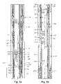
- FIGS. 1 a and 1 b are side, cross-sectional views of a wellbore having an exemplary solids placement tool suspended therein.
- FIG. 2 is an isometric view of an exemplary blast liner constructed in accordance with the present invention.
- FIG. 4 is an axial cross-section of an alternative blast liner wherein the flow channels are formed by milling into the interior surface of the liner body.
- FIGS. 5 a and 5 b depict an alternative embodiment for an exemplary blast liner assembly constructed in accordance with the present invention, which incorporates a progressive wear member to permit axial travel of the blast liner.
- FIG. 6 is a side, cross-sectional view of an alternative embodiment for an exemplary blast liner assembly which incorporates a lug and track mechanism to permit liner movement of the blast liner during operation.
- FIG. 7 is a side, cross-sectional view of the track mechanism for the assembly shown in FIG. 6 .
- FIGS. 1 a and 1 b depict an exemplary solids placement system 10 , which includes an extension sleeve assembly 12 that is secured to the lower end of a packer assembly 14 .
- the exemplary solids placement system 10 is a system for the placement of gravel within a wellbore 16 during gravel packing.
- gravel packing and proppant placement operations generally are well known to those of skill in the art and, therefore, will not be described in detail herein.
- the general outline of an exemplary gravel packing tool and system 10 is described in order to illustrate one use of the blast liner assembly of the present invention.
- the packer assembly 14 is a through-tubing packer assembly in that, once set, it can permit a service tool to be passed through its axial center.
- the packer assembly 14 and extension sleeve assembly 12 are run into the wellbore 16 .
- the packer assembly 14 is set against the cased side of the wellbore 16 , and an annulus 18 is thereby defined between the extension sleeve assembly 12 and the side of the wellbore 16 . In this situation, it is desired to place gravel 20 within the annulus 18 below the packer 14 .
- the extension sleeve assembly 12 has a generally cylindrical body 22 and defines an interior bore 24 with a pair of gravel flow ports 26 disposed therethrough.
- the extension sleeve assembly 12 also includes a blast liner retainer section, generally shown at 28 .
- a rotatable blast liner 30 is retained within the blast liner retainer section 28 .
- the solids placement system 10 also includes a service tool, generally shown at 32 , which is disposed through the packer assembly 14 and into the bore 24 of the extension sleeve assembly 12 .
- the service tool 32 is suspended upon a tubing string 34 that extends to the surface of the wellbore 16 .
- the tubing string 34 defines an axial flowbore 36 along its length.
- the other portion of the service tool 32 is a gravel placement tool 38 , which is secured to the lower end of the tubing string 34 and defines an axial, interior flowbore 40 along its length as well.
- Reverse recirculation ports 42 are disposed through a lower portion of the gravel placement tool 38 .
- Annular elastomeric seals 44 surround the gravel placement tool 38 at intervals along its length and serve to provide fluid sealing.
- the flowbore 40 of the gravel placement tool 38 contains a ball seat 46 .
- Located just above the ball seat 46 is a lateral gravel flow port 48 .
- FIGS. 2 , 3 , and 4 depict a blast liner 30 having a generally tubular liner body 50 with a pair of annular recessed portions 52 , 54 upon the outer surface 56 of the blast liner 30 .
- the radially inner surface 58 of the blast liner 30 includes a lower diversion portion 60 proximate the lower axial end 62 of the liner body 50 .
- the diversion portion 60 features a plurality of angled flow channels 64 .
- the flow channels 64 are formed between inwardly projecting vanes 66 , as shown in FIGS. 2 and 3 .
- flow channels may be formed by milling angled grooves 64 ′ into the radially inner surface 58 of the blast liner body 50 , as in alternative blast liner 30 ′ illustrated in FIG. 4 .
- the service tool 32 when the service tool 32 is disposed into the extension sleeve assembly 12 , it is landed by the interengagement of landing shoulders (not shown), in a manner known in the art.
- the lateral gravel flow port 48 of the service tool 32 When landed, the lateral gravel flow port 48 of the service tool 32 is located adjacent an upper portion of the rotatable blast liner 30 .
- An annular space 70 is defined between the blast liner 30 and the outer radial surface 72 of the gravel placement tool 38 .
- a ball plug 74 is dropped into the flowbore 36 of the tubing string 34 and lands upon the ball seat 46 . Once the ball plug 74 is seated, any fluids or slurries that are pumped down the flowbore 36 from the surface will be forced to exit the flowbore 36 through the gravel flow port 48 .
- FIGS. 1 a and 2 illustrate an exemplary annular primary wear, or impingement, area 80 having upper boundary 82 and lower boundary 84 upon the inner radial surface 58 of the blast liner 30 .
- the primary wear area 80 is the portion of the inner radial surface 58 of the blast liner 30 that lies proximate the gravel flow port 48 and receives the primary erosion wear from gravel exiting the port 48 . It is noted that annular bearings 86 , 88 , visible in FIG. 3 reside within the recessed portions 52 , 54 , respectively, to provide for standoff of the blast liner 30 from the liner retaining section 28 of the extension sleeve assembly 12 and helps ensure ease of rotation of the blast liner 30 within the liner retaining section 28 .
- FIGS. 5 a and 5 b depict portions of an alternative embodiment for a blast liner assembly, generally indicated at 90 , that is constructed in accordance with the present invention.
- the blast liner assembly 90 is used within the solids placement system 10 described earlier.
- the blast liner 30 , 30 ′ is caused to move axially as well as rotationally within the liner retaining section 28 during use, thereby further increasing the area of the sleeve that is exposed to wear and abrasion damage. Because the damage is spread upon a larger area, there is less severe damage to any point area upon the sleeve.
- the blast liner assembly 90 includes the blast liner 30 radially surrounding the gravel placement tool 38 and the liner retaining section 28 within the body 22 of the extension sleeve assembly 12 . It is noted that, although a blast liner 30 is depicted in FIGS. 5 a and 5 b , a blast liner having milled grooves to form the flow channels, such as exemplary blast liner 30 ′ might be used as well in the blast liner assembly 90 . Additionally, the blast liner assembly 90 includes an erodable or wearable bushing 92 that is retained within the liner retaining section 28 below the blast liner 30 .
- the wearable bushing 92 is formed of a readily erodable material, such as fiberglass, ceramic, or plastic.
- FIG. 5 a depicts the blast liner assembly 90 at the onset of flowing of gravel slurry
- FIG. 5 b depicts the assembly after slurry has been flowed for a period of time.
- the bushing 92 has become much shorter axially due to the frictional wear upon it provided by the blast liner 30 / 30 ′.
- the blast liner 30 / 30 ′ moves progressively downwardly within the liner retaining section 28 .
- the annular impingement area 80 is expanded axially as the upper boundary 82 of the impingement area progressively moves upwardly upon the inner surface 58 of the liner body 50 .
- the blast liner assembly 100 includes a blast liner 30 ′′ that is retained within the liner retaining section 28 ′ of the extension sleeve assembly 12 .
- the liner retaining section 28 ′ is inscribed with a lug track 102 , which is continuous. Details of the lug track 102 are better understood with reference to FIG. 7 , which depicts the liner retaining section 28 ′′ in cross-section apart from other components.
- the lug track 102 of the liner retaining section 28 ′′ is essentially a double-helix that includes a first helical path 104 which, in the manner of a spring, is made up of individual spiral winds 106 that are sequentially disposed along the length of the retaining section 28 ′′.
- the winds 106 are formed in a first spiral direction. For example, as illustrated in FIG. 7 , the path 104 and winds 106 proceed downwardly along the length of the retaining section 28 ′′ when traversed in a clockwise direction.
- the lug track 102 also includes a second helical path 108 that is inscribed within the retaining section 28 ′′.
- the second helical path 108 includes multiple individual spiral winds 110 , which are oriented in a second spiral direction from the first winds 106 . As depicted in FIG. 7 , the second helical path 108 and winds 110 proceed axially upwardly along the length of the retaining section 28 ′′ when traversed in a clockwise direction. Both axial ends of the spiral paths 106 , 110 are joined to one another at a joining point 112 . Only one joining point 112 is depicted in FIG. 7 . However, it will be understood that the opposite end of each spiral path 106 and 110 will be joined at a similar joining point at their opposite ends. As a result of the joining points 112 , a continuous double-helical path is provided for the lug track 102 . FIG.
- FIG. 6 illustrates that a lug 114 projects outwardly from the outer surface of the blast liner 30 ′′ and resides within the lug track 102 .
Landscapes
- Engineering & Computer Science (AREA)
- Geology (AREA)
- Life Sciences & Earth Sciences (AREA)
- Mining & Mineral Resources (AREA)
- Environmental & Geological Engineering (AREA)
- Fluid Mechanics (AREA)
- Physics & Mathematics (AREA)
- General Life Sciences & Earth Sciences (AREA)
- Geochemistry & Mineralogy (AREA)
- Mechanical Engineering (AREA)
- Structures Of Non-Positive Displacement Pumps (AREA)
- Blast Furnaces (AREA)
- Lining And Supports For Tunnels (AREA)
Abstract
Description
Claims (23)
Priority Applications (4)
| Application Number | Priority Date | Filing Date | Title |
|---|---|---|---|
| US10/748,099 US7096946B2 (en) | 2003-12-30 | 2003-12-30 | Rotating blast liner |
| PCT/US2004/040835 WO2005066453A1 (en) | 2003-12-30 | 2004-12-07 | Rotating blast liner |
| CA2552439A CA2552439C (en) | 2003-12-30 | 2004-12-07 | Rotating blast liner |
| GB0613524A GB2426992B (en) | 2003-12-30 | 2004-12-07 | Rotating blast liner |
Applications Claiming Priority (1)
| Application Number | Priority Date | Filing Date | Title |
|---|---|---|---|
| US10/748,099 US7096946B2 (en) | 2003-12-30 | 2003-12-30 | Rotating blast liner |
Publications (2)
| Publication Number | Publication Date |
|---|---|
| US20050145384A1 US20050145384A1 (en) | 2005-07-07 |
| US7096946B2 true US7096946B2 (en) | 2006-08-29 |
Family
ID=34710869
Family Applications (1)
| Application Number | Title | Priority Date | Filing Date |
|---|---|---|---|
| US10/748,099 Expired - Fee Related US7096946B2 (en) | 2003-12-30 | 2003-12-30 | Rotating blast liner |
Country Status (4)
| Country | Link |
|---|---|
| US (1) | US7096946B2 (en) |
| CA (1) | CA2552439C (en) |
| GB (1) | GB2426992B (en) |
| WO (1) | WO2005066453A1 (en) |
Cited By (56)
| Publication number | Priority date | Publication date | Assignee | Title |
|---|---|---|---|---|
| US20060076133A1 (en) * | 2004-10-08 | 2006-04-13 | Penno Andrew D | One trip liner conveyed gravel packing and cementing system |
| US20060191685A1 (en) * | 2005-02-25 | 2006-08-31 | Baker Hughes Incorporated | Multiple port cross-over design for frac-pack erosion mitigation |
| US20090255667A1 (en) * | 2007-12-04 | 2009-10-15 | Clem Nicholas J | Crossover Sub with Erosion Resistant Inserts |
| US20090301710A1 (en) * | 2008-06-06 | 2009-12-10 | Clem Nicholas J | Fixed Swirl Inducing Blast Liner |
| US20120031611A1 (en) * | 2010-08-09 | 2012-02-09 | Baker Hughes Incorporated | Erosion Migration Arrangement, Erodable Member and Method of Migrating a Slurry Flow Path |
| US8376038B2 (en) | 2010-04-30 | 2013-02-19 | Baker Hughes Incorporated | Slurry outlet in a gravel packing assembly |
| US8425651B2 (en) | 2010-07-30 | 2013-04-23 | Baker Hughes Incorporated | Nanomatrix metal composite |
| US8424610B2 (en) | 2010-03-05 | 2013-04-23 | Baker Hughes Incorporated | Flow control arrangement and method |
| US8573295B2 (en) | 2010-11-16 | 2013-11-05 | Baker Hughes Incorporated | Plug and method of unplugging a seat |
| US8584744B2 (en) | 2010-09-13 | 2013-11-19 | Baker Hughes Incorporated | Debris chamber with helical flow path for enhanced subterranean debris removal |
| AU2011205112B2 (en) * | 2010-08-25 | 2013-11-28 | Weatherford Technology Holdings, Llc | Self-orienting crossover tool |
| US8631876B2 (en) | 2011-04-28 | 2014-01-21 | Baker Hughes Incorporated | Method of making and using a functionally gradient composite tool |
| US8714268B2 (en) | 2009-12-08 | 2014-05-06 | Baker Hughes Incorporated | Method of making and using multi-component disappearing tripping ball |
| US8776884B2 (en) | 2010-08-09 | 2014-07-15 | Baker Hughes Incorporated | Formation treatment system and method |
| US8783365B2 (en) | 2011-07-28 | 2014-07-22 | Baker Hughes Incorporated | Selective hydraulic fracturing tool and method thereof |
| US9022107B2 (en) | 2009-12-08 | 2015-05-05 | Baker Hughes Incorporated | Dissolvable tool |
| US9033055B2 (en) | 2011-08-17 | 2015-05-19 | Baker Hughes Incorporated | Selectively degradable passage restriction and method |
| US9057242B2 (en) | 2011-08-05 | 2015-06-16 | Baker Hughes Incorporated | Method of controlling corrosion rate in downhole article, and downhole article having controlled corrosion rate |
| US20150167434A1 (en) * | 2013-12-18 | 2015-06-18 | Shell Oil Company | Downhole device for gas well deliquification |
| US9068428B2 (en) | 2012-02-13 | 2015-06-30 | Baker Hughes Incorporated | Selectively corrodible downhole article and method of use |
| US9079246B2 (en) | 2009-12-08 | 2015-07-14 | Baker Hughes Incorporated | Method of making a nanomatrix powder metal compact |
| US9080098B2 (en) | 2011-04-28 | 2015-07-14 | Baker Hughes Incorporated | Functionally gradient composite article |
| US9090956B2 (en) | 2011-08-30 | 2015-07-28 | Baker Hughes Incorporated | Aluminum alloy powder metal compact |
| US9090955B2 (en) | 2010-10-27 | 2015-07-28 | Baker Hughes Incorporated | Nanomatrix powder metal composite |
| US9097104B2 (en) | 2011-11-09 | 2015-08-04 | Weatherford Technology Holdings, Llc | Erosion resistant flow nozzle for downhole tool |
| US9101978B2 (en) | 2002-12-08 | 2015-08-11 | Baker Hughes Incorporated | Nanomatrix powder metal compact |
| US9109269B2 (en) | 2011-08-30 | 2015-08-18 | Baker Hughes Incorporated | Magnesium alloy powder metal compact |
| US9109429B2 (en) | 2002-12-08 | 2015-08-18 | Baker Hughes Incorporated | Engineered powder compact composite material |
| US9127515B2 (en) | 2010-10-27 | 2015-09-08 | Baker Hughes Incorporated | Nanomatrix carbon composite |
| US9133695B2 (en) | 2011-09-03 | 2015-09-15 | Baker Hughes Incorporated | Degradable shaped charge and perforating gun system |
| US9139928B2 (en) | 2011-06-17 | 2015-09-22 | Baker Hughes Incorporated | Corrodible downhole article and method of removing the article from downhole environment |
| US9187990B2 (en) | 2011-09-03 | 2015-11-17 | Baker Hughes Incorporated | Method of using a degradable shaped charge and perforating gun system |
| US9227243B2 (en) | 2009-12-08 | 2016-01-05 | Baker Hughes Incorporated | Method of making a powder metal compact |
| US9243475B2 (en) | 2009-12-08 | 2016-01-26 | Baker Hughes Incorporated | Extruded powder metal compact |
| US9267347B2 (en) | 2009-12-08 | 2016-02-23 | Baker Huges Incorporated | Dissolvable tool |
| US9347119B2 (en) | 2011-09-03 | 2016-05-24 | Baker Hughes Incorporated | Degradable high shock impedance material |
| US9605508B2 (en) | 2012-05-08 | 2017-03-28 | Baker Hughes Incorporated | Disintegrable and conformable metallic seal, and method of making the same |
| US9643250B2 (en) | 2011-07-29 | 2017-05-09 | Baker Hughes Incorporated | Method of controlling the corrosion rate of alloy particles, alloy particle with controlled corrosion rate, and articles comprising the particle |
| US9643144B2 (en) | 2011-09-02 | 2017-05-09 | Baker Hughes Incorporated | Method to generate and disperse nanostructures in a composite material |
| US9677383B2 (en) | 2013-02-28 | 2017-06-13 | Weatherford Technology Holdings, Llc | Erosion ports for shunt tubes |
| US9682425B2 (en) | 2009-12-08 | 2017-06-20 | Baker Hughes Incorporated | Coated metallic powder and method of making the same |
| US9707739B2 (en) | 2011-07-22 | 2017-07-18 | Baker Hughes Incorporated | Intermetallic metallic composite, method of manufacture thereof and articles comprising the same |
| US9816339B2 (en) | 2013-09-03 | 2017-11-14 | Baker Hughes, A Ge Company, Llc | Plug reception assembly and method of reducing restriction in a borehole |
| US9833838B2 (en) | 2011-07-29 | 2017-12-05 | Baker Hughes, A Ge Company, Llc | Method of controlling the corrosion rate of alloy particles, alloy particle with controlled corrosion rate, and articles comprising the particle |
| US9856547B2 (en) | 2011-08-30 | 2018-01-02 | Bakers Hughes, A Ge Company, Llc | Nanostructured powder metal compact |
| US9910026B2 (en) | 2015-01-21 | 2018-03-06 | Baker Hughes, A Ge Company, Llc | High temperature tracers for downhole detection of produced water |
| US9926766B2 (en) | 2012-01-25 | 2018-03-27 | Baker Hughes, A Ge Company, Llc | Seat for a tubular treating system |
| US10016810B2 (en) | 2015-12-14 | 2018-07-10 | Baker Hughes, A Ge Company, Llc | Methods of manufacturing degradable tools using a galvanic carrier and tools manufactured thereof |
| US10221637B2 (en) | 2015-08-11 | 2019-03-05 | Baker Hughes, A Ge Company, Llc | Methods of manufacturing dissolvable tools via liquid-solid state molding |
| US10240419B2 (en) | 2009-12-08 | 2019-03-26 | Baker Hughes, A Ge Company, Llc | Downhole flow inhibition tool and method of unplugging a seat |
| US10378303B2 (en) | 2015-03-05 | 2019-08-13 | Baker Hughes, A Ge Company, Llc | Downhole tool and method of forming the same |
| US10947823B2 (en) | 2017-08-03 | 2021-03-16 | Halliburton Energy Services, Inc. | Erosive slurry diverter |
| US11167343B2 (en) | 2014-02-21 | 2021-11-09 | Terves, Llc | Galvanically-active in situ formed particles for controlled rate dissolving tools |
| US11365164B2 (en) | 2014-02-21 | 2022-06-21 | Terves, Llc | Fluid activated disintegrating metal system |
| US11649526B2 (en) | 2017-07-27 | 2023-05-16 | Terves, Llc | Degradable metal matrix composite |
| US12018356B2 (en) | 2014-04-18 | 2024-06-25 | Terves Inc. | Galvanically-active in situ formed particles for controlled rate dissolving tools |
Families Citing this family (9)
| Publication number | Priority date | Publication date | Assignee | Title |
|---|---|---|---|---|
| US20060213671A1 (en) * | 2005-03-11 | 2006-09-28 | Li Liping J | Erosion resistant crossover for fracturing/gravel packing |
| US7559357B2 (en) * | 2006-10-25 | 2009-07-14 | Baker Hughes Incorporated | Frac-pack casing saver |
| US7726403B2 (en) * | 2007-10-26 | 2010-06-01 | Halliburton Energy Services, Inc. | Apparatus and method for ratcheting stimulation tool |
| WO2014066144A1 (en) * | 2012-10-24 | 2014-05-01 | Oxane Materials, Inc. | Immobile proppants |
| US10287829B2 (en) | 2014-12-22 | 2019-05-14 | Colorado School Of Mines | Method and apparatus to rotate subsurface wellbore casing |
| CN105298534B (en) * | 2015-11-25 | 2017-09-15 | 中国矿业大学(北京) | A kind of lighter hydrocarbons blastingfracture permeability improvement device |
| US10506890B2 (en) * | 2016-03-11 | 2019-12-17 | Toyoda Gosei Co., Ltd. | Cup holder |
| CN106194142A (en) * | 2016-08-30 | 2016-12-07 | 中国石油集团川庆钻探工程有限公司长庆井下技术作业公司 | A kind of horizontal well volume fracturing is with spiral double-deck diversion oil pipe |
| CN109610253B (en) * | 2018-11-19 | 2020-04-17 | 西南交通大学 | Method for evaluating slurry leakage hazard grade of ballastless track subgrade |
Citations (18)
| Publication number | Priority date | Publication date | Assignee | Title |
|---|---|---|---|---|
| US2116408A (en) | 1936-11-04 | 1938-05-03 | Jr Charles M O'leary | Floating cementing equipment |
| US2224538A (en) * | 1939-06-02 | 1940-12-10 | Standard Oil Dev Co | Method and apparatus for gravelpacking wells |
| US3034912A (en) | 1958-12-29 | 1962-05-15 | Phillips Petroleum Co | Elimination of abrasion of well tubing by production fluid containing abrasive material |
| US3101784A (en) * | 1961-10-16 | 1963-08-27 | Smith Co Howard | Rotary wash screen setting combination and rotary washing tool therefor |
| US3358764A (en) | 1965-07-16 | 1967-12-19 | Phillips Petroleum Co | Method of fracturing subterranean strata |
| US3382930A (en) | 1966-03-09 | 1968-05-14 | Keystone Valve Corp | Blast joint |
| US3576222A (en) | 1969-04-01 | 1971-04-27 | Gulf Research Development Co | Hydraulic jet drill bit |
| US3727691A (en) | 1970-12-16 | 1973-04-17 | Exxon Production Research Co | Method and apparatus for treating subterranean formations |
| US4211440A (en) | 1975-07-31 | 1980-07-08 | Bergstrom Arthur E | Compensated blast joint for oil well production tubing |
| US4995456A (en) | 1990-05-04 | 1991-02-26 | Atlantic Richfield Company | Gravel pack well completions |
| US5016921A (en) | 1990-03-14 | 1991-05-21 | Claycomb Jack R | Durable blast joint with hydrostatic driver |
| US5059043A (en) | 1989-04-24 | 1991-10-22 | Vermont American Corporation | Blast joint for snubbing unit |
| US5549333A (en) | 1994-09-08 | 1996-08-27 | Uherek, Sr.; Robert J. | Blast joint |
| US5636691A (en) * | 1995-09-18 | 1997-06-10 | Halliburton Energy Services, Inc. | Abrasive slurry delivery apparatus and methods of using same |
| US5730223A (en) * | 1996-01-24 | 1998-03-24 | Halliburton Energy Services, Inc. | Sand control screen assembly having an adjustable flow rate and associated methods of completing a subterranean well |
| US6269879B1 (en) | 2000-03-20 | 2001-08-07 | Harper Boyd | Sleeve liner for wireline entry sub assembly |
| US6484807B2 (en) * | 2000-11-29 | 2002-11-26 | Cooper Cameron Corporation | Wellhead assembly for injecting a fluid into a well and method of using the same |
| US6491097B1 (en) * | 2000-12-14 | 2002-12-10 | Halliburton Energy Services, Inc. | Abrasive slurry delivery apparatus and methods of using same |
-
2003
- 2003-12-30 US US10/748,099 patent/US7096946B2/en not_active Expired - Fee Related
-
2004
- 2004-12-07 GB GB0613524A patent/GB2426992B/en not_active Expired - Fee Related
- 2004-12-07 CA CA2552439A patent/CA2552439C/en not_active Expired - Fee Related
- 2004-12-07 WO PCT/US2004/040835 patent/WO2005066453A1/en not_active Ceased
Patent Citations (18)
| Publication number | Priority date | Publication date | Assignee | Title |
|---|---|---|---|---|
| US2116408A (en) | 1936-11-04 | 1938-05-03 | Jr Charles M O'leary | Floating cementing equipment |
| US2224538A (en) * | 1939-06-02 | 1940-12-10 | Standard Oil Dev Co | Method and apparatus for gravelpacking wells |
| US3034912A (en) | 1958-12-29 | 1962-05-15 | Phillips Petroleum Co | Elimination of abrasion of well tubing by production fluid containing abrasive material |
| US3101784A (en) * | 1961-10-16 | 1963-08-27 | Smith Co Howard | Rotary wash screen setting combination and rotary washing tool therefor |
| US3358764A (en) | 1965-07-16 | 1967-12-19 | Phillips Petroleum Co | Method of fracturing subterranean strata |
| US3382930A (en) | 1966-03-09 | 1968-05-14 | Keystone Valve Corp | Blast joint |
| US3576222A (en) | 1969-04-01 | 1971-04-27 | Gulf Research Development Co | Hydraulic jet drill bit |
| US3727691A (en) | 1970-12-16 | 1973-04-17 | Exxon Production Research Co | Method and apparatus for treating subterranean formations |
| US4211440A (en) | 1975-07-31 | 1980-07-08 | Bergstrom Arthur E | Compensated blast joint for oil well production tubing |
| US5059043A (en) | 1989-04-24 | 1991-10-22 | Vermont American Corporation | Blast joint for snubbing unit |
| US5016921A (en) | 1990-03-14 | 1991-05-21 | Claycomb Jack R | Durable blast joint with hydrostatic driver |
| US4995456A (en) | 1990-05-04 | 1991-02-26 | Atlantic Richfield Company | Gravel pack well completions |
| US5549333A (en) | 1994-09-08 | 1996-08-27 | Uherek, Sr.; Robert J. | Blast joint |
| US5636691A (en) * | 1995-09-18 | 1997-06-10 | Halliburton Energy Services, Inc. | Abrasive slurry delivery apparatus and methods of using same |
| US5730223A (en) * | 1996-01-24 | 1998-03-24 | Halliburton Energy Services, Inc. | Sand control screen assembly having an adjustable flow rate and associated methods of completing a subterranean well |
| US6269879B1 (en) | 2000-03-20 | 2001-08-07 | Harper Boyd | Sleeve liner for wireline entry sub assembly |
| US6484807B2 (en) * | 2000-11-29 | 2002-11-26 | Cooper Cameron Corporation | Wellhead assembly for injecting a fluid into a well and method of using the same |
| US6491097B1 (en) * | 2000-12-14 | 2002-12-10 | Halliburton Energy Services, Inc. | Abrasive slurry delivery apparatus and methods of using same |
Cited By (79)
| Publication number | Priority date | Publication date | Assignee | Title |
|---|---|---|---|---|
| US9109429B2 (en) | 2002-12-08 | 2015-08-18 | Baker Hughes Incorporated | Engineered powder compact composite material |
| US9101978B2 (en) | 2002-12-08 | 2015-08-11 | Baker Hughes Incorporated | Nanomatrix powder metal compact |
| US7337840B2 (en) * | 2004-10-08 | 2008-03-04 | Halliburton Energy Services, Inc. | One trip liner conveyed gravel packing and cementing system |
| US20080110620A1 (en) * | 2004-10-08 | 2008-05-15 | Halliburton Energy Services, Inc. | One Trip Liner conveyed Gravel Packing and Cementing System |
| US20060076133A1 (en) * | 2004-10-08 | 2006-04-13 | Penno Andrew D | One trip liner conveyed gravel packing and cementing system |
| US20060191685A1 (en) * | 2005-02-25 | 2006-08-31 | Baker Hughes Incorporated | Multiple port cross-over design for frac-pack erosion mitigation |
| US7503384B2 (en) * | 2005-02-25 | 2009-03-17 | Baker Hughes Incorporated | Multiple port cross-over design for frac-pack erosion mitigation |
| US20090255667A1 (en) * | 2007-12-04 | 2009-10-15 | Clem Nicholas J | Crossover Sub with Erosion Resistant Inserts |
| US8371369B2 (en) | 2007-12-04 | 2013-02-12 | Baker Hughes Incorporated | Crossover sub with erosion resistant inserts |
| US8678079B2 (en) | 2008-06-06 | 2014-03-25 | Baker Hughes Incorporated | Fixed swirl inducing blast liner |
| US20090301710A1 (en) * | 2008-06-06 | 2009-12-10 | Clem Nicholas J | Fixed Swirl Inducing Blast Liner |
| US9079246B2 (en) | 2009-12-08 | 2015-07-14 | Baker Hughes Incorporated | Method of making a nanomatrix powder metal compact |
| US10240419B2 (en) | 2009-12-08 | 2019-03-26 | Baker Hughes, A Ge Company, Llc | Downhole flow inhibition tool and method of unplugging a seat |
| US9227243B2 (en) | 2009-12-08 | 2016-01-05 | Baker Hughes Incorporated | Method of making a powder metal compact |
| US9243475B2 (en) | 2009-12-08 | 2016-01-26 | Baker Hughes Incorporated | Extruded powder metal compact |
| US9267347B2 (en) | 2009-12-08 | 2016-02-23 | Baker Huges Incorporated | Dissolvable tool |
| US9682425B2 (en) | 2009-12-08 | 2017-06-20 | Baker Hughes Incorporated | Coated metallic powder and method of making the same |
| US9022107B2 (en) | 2009-12-08 | 2015-05-05 | Baker Hughes Incorporated | Dissolvable tool |
| US8714268B2 (en) | 2009-12-08 | 2014-05-06 | Baker Hughes Incorporated | Method of making and using multi-component disappearing tripping ball |
| US10669797B2 (en) | 2009-12-08 | 2020-06-02 | Baker Hughes, A Ge Company, Llc | Tool configured to dissolve in a selected subsurface environment |
| US8424610B2 (en) | 2010-03-05 | 2013-04-23 | Baker Hughes Incorporated | Flow control arrangement and method |
| US8376038B2 (en) | 2010-04-30 | 2013-02-19 | Baker Hughes Incorporated | Slurry outlet in a gravel packing assembly |
| US8425651B2 (en) | 2010-07-30 | 2013-04-23 | Baker Hughes Incorporated | Nanomatrix metal composite |
| US8776884B2 (en) | 2010-08-09 | 2014-07-15 | Baker Hughes Incorporated | Formation treatment system and method |
| US20120031611A1 (en) * | 2010-08-09 | 2012-02-09 | Baker Hughes Incorporated | Erosion Migration Arrangement, Erodable Member and Method of Migrating a Slurry Flow Path |
| US8695709B2 (en) | 2010-08-25 | 2014-04-15 | Weatherford/Lamb, Inc. | Self-orienting crossover tool |
| AU2011205112B2 (en) * | 2010-08-25 | 2013-11-28 | Weatherford Technology Holdings, Llc | Self-orienting crossover tool |
| US8844619B2 (en) | 2010-09-13 | 2014-09-30 | Baker Hughes Incorporated | Debris chamber with helical flow path for enhanced subterranean debris removal |
| US8584744B2 (en) | 2010-09-13 | 2013-11-19 | Baker Hughes Incorporated | Debris chamber with helical flow path for enhanced subterranean debris removal |
| US9353590B2 (en) | 2010-09-13 | 2016-05-31 | Baker Hughes Incorporated | Debris chamber with helical flow path for enhanced subterranean debris removal |
| US9127515B2 (en) | 2010-10-27 | 2015-09-08 | Baker Hughes Incorporated | Nanomatrix carbon composite |
| US9090955B2 (en) | 2010-10-27 | 2015-07-28 | Baker Hughes Incorporated | Nanomatrix powder metal composite |
| US8573295B2 (en) | 2010-11-16 | 2013-11-05 | Baker Hughes Incorporated | Plug and method of unplugging a seat |
| US8631876B2 (en) | 2011-04-28 | 2014-01-21 | Baker Hughes Incorporated | Method of making and using a functionally gradient composite tool |
| US9080098B2 (en) | 2011-04-28 | 2015-07-14 | Baker Hughes Incorporated | Functionally gradient composite article |
| US9631138B2 (en) | 2011-04-28 | 2017-04-25 | Baker Hughes Incorporated | Functionally gradient composite article |
| US10335858B2 (en) | 2011-04-28 | 2019-07-02 | Baker Hughes, A Ge Company, Llc | Method of making and using a functionally gradient composite tool |
| US9139928B2 (en) | 2011-06-17 | 2015-09-22 | Baker Hughes Incorporated | Corrodible downhole article and method of removing the article from downhole environment |
| US9926763B2 (en) | 2011-06-17 | 2018-03-27 | Baker Hughes, A Ge Company, Llc | Corrodible downhole article and method of removing the article from downhole environment |
| US10697266B2 (en) | 2011-07-22 | 2020-06-30 | Baker Hughes, A Ge Company, Llc | Intermetallic metallic composite, method of manufacture thereof and articles comprising the same |
| US9707739B2 (en) | 2011-07-22 | 2017-07-18 | Baker Hughes Incorporated | Intermetallic metallic composite, method of manufacture thereof and articles comprising the same |
| US8783365B2 (en) | 2011-07-28 | 2014-07-22 | Baker Hughes Incorporated | Selective hydraulic fracturing tool and method thereof |
| US9833838B2 (en) | 2011-07-29 | 2017-12-05 | Baker Hughes, A Ge Company, Llc | Method of controlling the corrosion rate of alloy particles, alloy particle with controlled corrosion rate, and articles comprising the particle |
| US10092953B2 (en) | 2011-07-29 | 2018-10-09 | Baker Hughes, A Ge Company, Llc | Method of controlling the corrosion rate of alloy particles, alloy particle with controlled corrosion rate, and articles comprising the particle |
| US9643250B2 (en) | 2011-07-29 | 2017-05-09 | Baker Hughes Incorporated | Method of controlling the corrosion rate of alloy particles, alloy particle with controlled corrosion rate, and articles comprising the particle |
| US9057242B2 (en) | 2011-08-05 | 2015-06-16 | Baker Hughes Incorporated | Method of controlling corrosion rate in downhole article, and downhole article having controlled corrosion rate |
| US10301909B2 (en) | 2011-08-17 | 2019-05-28 | Baker Hughes, A Ge Company, Llc | Selectively degradable passage restriction |
| US9033055B2 (en) | 2011-08-17 | 2015-05-19 | Baker Hughes Incorporated | Selectively degradable passage restriction and method |
| US9090956B2 (en) | 2011-08-30 | 2015-07-28 | Baker Hughes Incorporated | Aluminum alloy powder metal compact |
| US10737321B2 (en) | 2011-08-30 | 2020-08-11 | Baker Hughes, A Ge Company, Llc | Magnesium alloy powder metal compact |
| US9802250B2 (en) | 2011-08-30 | 2017-10-31 | Baker Hughes | Magnesium alloy powder metal compact |
| US9109269B2 (en) | 2011-08-30 | 2015-08-18 | Baker Hughes Incorporated | Magnesium alloy powder metal compact |
| US11090719B2 (en) | 2011-08-30 | 2021-08-17 | Baker Hughes, A Ge Company, Llc | Aluminum alloy powder metal compact |
| US9856547B2 (en) | 2011-08-30 | 2018-01-02 | Bakers Hughes, A Ge Company, Llc | Nanostructured powder metal compact |
| US9925589B2 (en) | 2011-08-30 | 2018-03-27 | Baker Hughes, A Ge Company, Llc | Aluminum alloy powder metal compact |
| US9643144B2 (en) | 2011-09-02 | 2017-05-09 | Baker Hughes Incorporated | Method to generate and disperse nanostructures in a composite material |
| US9347119B2 (en) | 2011-09-03 | 2016-05-24 | Baker Hughes Incorporated | Degradable high shock impedance material |
| US9133695B2 (en) | 2011-09-03 | 2015-09-15 | Baker Hughes Incorporated | Degradable shaped charge and perforating gun system |
| US9187990B2 (en) | 2011-09-03 | 2015-11-17 | Baker Hughes Incorporated | Method of using a degradable shaped charge and perforating gun system |
| US9097104B2 (en) | 2011-11-09 | 2015-08-04 | Weatherford Technology Holdings, Llc | Erosion resistant flow nozzle for downhole tool |
| US9926766B2 (en) | 2012-01-25 | 2018-03-27 | Baker Hughes, A Ge Company, Llc | Seat for a tubular treating system |
| US9068428B2 (en) | 2012-02-13 | 2015-06-30 | Baker Hughes Incorporated | Selectively corrodible downhole article and method of use |
| US9605508B2 (en) | 2012-05-08 | 2017-03-28 | Baker Hughes Incorporated | Disintegrable and conformable metallic seal, and method of making the same |
| US10612659B2 (en) | 2012-05-08 | 2020-04-07 | Baker Hughes Oilfield Operations, Llc | Disintegrable and conformable metallic seal, and method of making the same |
| US9677383B2 (en) | 2013-02-28 | 2017-06-13 | Weatherford Technology Holdings, Llc | Erosion ports for shunt tubes |
| US9816339B2 (en) | 2013-09-03 | 2017-11-14 | Baker Hughes, A Ge Company, Llc | Plug reception assembly and method of reducing restriction in a borehole |
| US20150167434A1 (en) * | 2013-12-18 | 2015-06-18 | Shell Oil Company | Downhole device for gas well deliquification |
| US11613952B2 (en) | 2014-02-21 | 2023-03-28 | Terves, Llc | Fluid activated disintegrating metal system |
| US12031400B2 (en) | 2014-02-21 | 2024-07-09 | Terves, Llc | Fluid activated disintegrating metal system |
| US11167343B2 (en) | 2014-02-21 | 2021-11-09 | Terves, Llc | Galvanically-active in situ formed particles for controlled rate dissolving tools |
| US11365164B2 (en) | 2014-02-21 | 2022-06-21 | Terves, Llc | Fluid activated disintegrating metal system |
| US12018356B2 (en) | 2014-04-18 | 2024-06-25 | Terves Inc. | Galvanically-active in situ formed particles for controlled rate dissolving tools |
| US9910026B2 (en) | 2015-01-21 | 2018-03-06 | Baker Hughes, A Ge Company, Llc | High temperature tracers for downhole detection of produced water |
| US10378303B2 (en) | 2015-03-05 | 2019-08-13 | Baker Hughes, A Ge Company, Llc | Downhole tool and method of forming the same |
| US10221637B2 (en) | 2015-08-11 | 2019-03-05 | Baker Hughes, A Ge Company, Llc | Methods of manufacturing dissolvable tools via liquid-solid state molding |
| US10016810B2 (en) | 2015-12-14 | 2018-07-10 | Baker Hughes, A Ge Company, Llc | Methods of manufacturing degradable tools using a galvanic carrier and tools manufactured thereof |
| US11649526B2 (en) | 2017-07-27 | 2023-05-16 | Terves, Llc | Degradable metal matrix composite |
| US11898223B2 (en) | 2017-07-27 | 2024-02-13 | Terves, Llc | Degradable metal matrix composite |
| US10947823B2 (en) | 2017-08-03 | 2021-03-16 | Halliburton Energy Services, Inc. | Erosive slurry diverter |
Also Published As
| Publication number | Publication date |
|---|---|
| CA2552439C (en) | 2010-04-20 |
| GB2426992A8 (en) | 2007-03-02 |
| CA2552439A1 (en) | 2005-07-21 |
| GB2426992B (en) | 2008-07-09 |
| GB0613524D0 (en) | 2006-08-30 |
| WO2005066453A1 (en) | 2005-07-21 |
| GB2426992A (en) | 2006-12-13 |
| US20050145384A1 (en) | 2005-07-07 |
Similar Documents
| Publication | Publication Date | Title |
|---|---|---|
| US7096946B2 (en) | Rotating blast liner | |
| US6491097B1 (en) | Abrasive slurry delivery apparatus and methods of using same | |
| CA2585743C (en) | Systems and methods for completing a multiple zone well | |
| AU2005233602B2 (en) | Completion with telescoping perforation & fracturing tool | |
| US6672405B2 (en) | Perforating gun assembly for use in multi-stage stimulation operations | |
| EP0789131B1 (en) | Downhole abrasive slurry delivery apparatus | |
| EP3412863B1 (en) | Screen or screen assembly including valves | |
| US8978765B2 (en) | System and method for operating multiple valves | |
| CN101675212A (en) | Improved system and method for stimulating multiple production zones in a wellbore | |
| WO2007123909A2 (en) | Downhole flow control apparatus, operable via surface applied pressure | |
| US11332989B2 (en) | Downhole disconnect tool | |
| US10465478B2 (en) | Toe valve | |
| US11808106B2 (en) | Multi-stage hydraulic fracturing tool and system | |
| CN109477365A (en) | Top-down extrusion system and method | |
| WO2016028311A1 (en) | Sealing plug and method of removing same from a well | |
| US9896908B2 (en) | Well bore stimulation valve | |
| WO2021061503A1 (en) | Modular side pocket icd | |
| US8776888B2 (en) | Valve for wellbore applications | |
| Coronado et al. | J asser et al.(43) Pub. Date: Jul. 7, 2005 | |
| US11215030B2 (en) | Locking backpressure valve with shiftable valve seat | |
| CA3010364C (en) | Burst plug assembly with choke insert, fracturing tool and method of fracturing with same | |
| CA2761477C (en) | System and method for operating multiple valves | |
| US20210372225A1 (en) | Locking backpressure valve | |
| NO20251399A1 (en) | Downhole scraper for radial and axial motion |
Legal Events
| Date | Code | Title | Description |
|---|---|---|---|
| AS | Assignment |
Owner name: BAKER HUGHES INCORPORATED, TEXAS Free format text: ASSIGNMENT OF ASSIGNORS INTEREST;ASSIGNORS:JASSER, RAMI J.;CORONADO, MARTIN P.;SALERNI, JOHN V.;AND OTHERS;REEL/FRAME:015106/0233;SIGNING DATES FROM 20040813 TO 20040818 |
|
| FEPP | Fee payment procedure |
Free format text: PAYOR NUMBER ASSIGNED (ORIGINAL EVENT CODE: ASPN); ENTITY STATUS OF PATENT OWNER: LARGE ENTITY |
|
| FPAY | Fee payment |
Year of fee payment: 4 |
|
| REMI | Maintenance fee reminder mailed | ||
| LAPS | Lapse for failure to pay maintenance fees | ||
| STCH | Information on status: patent discontinuation |
Free format text: PATENT EXPIRED DUE TO NONPAYMENT OF MAINTENANCE FEES UNDER 37 CFR 1.362 |
|
| STCH | Information on status: patent discontinuation |
Free format text: PATENT EXPIRED DUE TO NONPAYMENT OF MAINTENANCE FEES UNDER 37 CFR 1.362 |
|
| FP | Lapsed due to failure to pay maintenance fee |
Effective date: 20140829 |