US7088336B2 - Pushbutton - Google Patents
Pushbutton Download PDFInfo
- Publication number
- US7088336B2 US7088336B2 US10/714,961 US71496103A US7088336B2 US 7088336 B2 US7088336 B2 US 7088336B2 US 71496103 A US71496103 A US 71496103A US 7088336 B2 US7088336 B2 US 7088336B2
- Authority
- US
- United States
- Prior art keywords
- button
- elastic
- pushbutton
- panel
- lateral side
- Prior art date
- Legal status (The legal status is an assumption and is not a legal conclusion. Google has not performed a legal analysis and makes no representation as to the accuracy of the status listed.)
- Expired - Fee Related, expires
Links
- 230000006835 compression Effects 0.000 claims description 3
- 238000007906 compression Methods 0.000 claims description 3
- 238000012986 modification Methods 0.000 description 1
- 230000004048 modification Effects 0.000 description 1
Images


Classifications
-
- H—ELECTRICITY
- H01—ELECTRIC ELEMENTS
- H01H—ELECTRIC SWITCHES; RELAYS; SELECTORS; EMERGENCY PROTECTIVE DEVICES
- H01H13/00—Switches having rectilinearly-movable operating part or parts adapted for pushing or pulling in one direction only, e.g. push-button switch
- H01H13/70—Switches having rectilinearly-movable operating part or parts adapted for pushing or pulling in one direction only, e.g. push-button switch having a plurality of operating members associated with different sets of contacts, e.g. keyboard
- H01H13/702—Switches having rectilinearly-movable operating part or parts adapted for pushing or pulling in one direction only, e.g. push-button switch having a plurality of operating members associated with different sets of contacts, e.g. keyboard with contacts carried by or formed from layers in a multilayer structure, e.g. membrane switches
- H01H13/705—Switches having rectilinearly-movable operating part or parts adapted for pushing or pulling in one direction only, e.g. push-button switch having a plurality of operating members associated with different sets of contacts, e.g. keyboard with contacts carried by or formed from layers in a multilayer structure, e.g. membrane switches characterised by construction, mounting or arrangement of operating parts, e.g. push-buttons or keys
-
- H—ELECTRICITY
- H01—ELECTRIC ELEMENTS
- H01H—ELECTRIC SWITCHES; RELAYS; SELECTORS; EMERGENCY PROTECTIVE DEVICES
- H01H2219/00—Legends
- H01H2219/002—Legends replaceable; adaptable
- H01H2219/01—Liquid crystal
-
- H—ELECTRICITY
- H01—ELECTRIC ELEMENTS
- H01H—ELECTRIC SWITCHES; RELAYS; SELECTORS; EMERGENCY PROTECTIVE DEVICES
- H01H2221/00—Actuators
- H01H2221/036—Return force
- H01H2221/044—Elastic part on actuator or casing
-
- H—ELECTRICITY
- H01—ELECTRIC ELEMENTS
- H01H—ELECTRIC SWITCHES; RELAYS; SELECTORS; EMERGENCY PROTECTIVE DEVICES
- H01H2229/00—Manufacturing
- H01H2229/044—Injection moulding
-
- H—ELECTRICITY
- H01—ELECTRIC ELEMENTS
- H01H—ELECTRIC SWITCHES; RELAYS; SELECTORS; EMERGENCY PROTECTIVE DEVICES
- H01H2231/00—Applications
- H01H2231/036—Radio; TV
Definitions
- the invention relates to an improved pushbutton and particularly to a pushbutton for use in thin LCD panels to save space.
- LCD devices nowadays a growing number of conventional CRT display devices of desktop computers have been replaced by LCD devices.
- the LCD device has gradually become a standard feature of the standard desktop computer.
- the LCD devices on the market also have constant innovations both in the design and structure,aiming at enlarging display panels and reducing thickness and weight.
- the accessory that most directly relates to this concern is the multifunctional pushbutton for adjusting display brightness, contrast, and the like.
- FIGS. 1 and 2 for a conventional LCD device. It includes a panel, 1 , in which operation button cluster A occupies a large area. This mainly results in a button as a touch approach. Also refer to FIGS. 3A and 3B for the structure of a conventional plane touch button. It has a button, 11 , with the periphery connecting to elastic strips 111 . When the button is subject to pressure, its surface partially sinks. Such a structure requires a greater flat area for the button cluster A. As a result, when the button cluster A is wedged in the LCD panel, 1 , it also takes a relative large area on panel 1 . Consequently a greater area has to be allocated to accommodate the button cluster A during design of LCD panel 1 . This is against the thin and light design trend of the LCD device.
- the primary object of the invention is to provide an improved pushbutton that alters the conventional plane touch structure to a vertical design so that it takes less space on the LCD panel and may greatly shrink the size of the entire panel.
- the pushbutton according to the invention mainly is adopted for fabricating thin and light LCD panels. It has a pair of elastic sections connecting to a button in a protrusive manner.
- the elastic section has an undulate buffer member formed of an elastic and flexible strip, abutting a lateral side of the button so that the entire body becomes vertical.
- the vertical structure greatly reduces the occupied space on the panel more than the conventional plane touch design. As a result, the size of the panel may be shrunk.
- FIG. 1 is a pictorial view of a conventional pushbutton cluster embedded in a panel.
- FIG. 2 is a perspective view of a conventional pushbutton embedded in a panel.
- FIGS. 3A and 3B are sectional views of a conventional pushbutton in operating conditions.
- FIGS. 4A and 4B are schematic views of the pushbutton of the invention.
- FIGS. 5A and 5B are sectional views of the pushbutton of the invention in operating conditions.
- FIG. 6 is a pictorial view of the invention embedded in a panel.
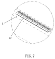
- FIG. 7 is a perspective view of the invention embedded in a panel.
- the improved pushbutton according to the invention aims at altering the horizontal touch button structure of the conventional LCD panel to a vertical structure so that it occupies less space on the LCD panel and the size of the entire panel may be reduced.
- FIGS. 4A and 4B for the structure of a single pushbutton according to the invention. It includes a pair of elastic sections 21 that sandwiches a button 22 there between.
- Each of the elastic sections 21 includes a top ridge 211 and a bottom ridge 212 that bridge a set of buffer members 213 .
- the buffer member 213 is made of an elastic and flexible strip formed in a undulate manner abutting a lateral side of the button 22 .
- the top ridge 211 is connected to the button 22 on a desired location to allow the button 22 to be partially extended outside the elastic sections 21 . It also may be formed by extending the undulate buffer member 213 with a top section thereof connecting to the lateral side of the button 22 .
- the pushbutton of the invention when the pushbutton of the invention is wedged in a LCD panel 5 , it straddles a switch 3 of a circuit board 4 inside the LCD panel. Namely, the bottom ridge 212 is stacked on the switch 3 with the bottom side of the button 22 in contact with the surface of the switch 3 .
- the button 22 when the button 22 is pressed and sinks slightly, due to the elasticity and flexibility of the buffer member 213 , it is compressed and deformed instantly. Therefore the button 22 is pressed and lowered quickly to compress the switch 3 , to establish electric connection between a conductive member 31 inside and a connection point 41 of the circuit board 4 .
- the elasticity of the buffer member 213 When the compression force is released, the elasticity of the buffer member 213 generates a returning force to enable the buffer member 213 to be extended to its original condition before compression as shown in FIG. 5A .
- the button 22 also returns to its original position.
- FIGS. 6 and 7 for the pushbutton of the invention that is juxtaposed to form a button row B on the panel 5 .
- each button adopts a vertical structure, it takes much less space than the conventional design of plane touch button cluster A shown in FIGS. 1 and 2 .
- the LCD panel may be made smaller.
Landscapes
- Push-Button Switches (AREA)
Abstract
Description
Claims (3)
Applications Claiming Priority (2)
| Application Number | Priority Date | Filing Date | Title |
|---|---|---|---|
| TW92203619 | 2003-03-11 | ||
| TW092203619U TW568337U (en) | 2003-03-11 | 2003-03-11 | Improved button structure |
Publications (2)
| Publication Number | Publication Date |
|---|---|
| US20050023122A1 US20050023122A1 (en) | 2005-02-03 |
| US7088336B2 true US7088336B2 (en) | 2006-08-08 |
Family
ID=32504453
Family Applications (1)
| Application Number | Title | Priority Date | Filing Date |
|---|---|---|---|
| US10/714,961 Expired - Fee Related US7088336B2 (en) | 2003-03-11 | 2003-11-18 | Pushbutton |
Country Status (2)
| Country | Link |
|---|---|
| US (1) | US7088336B2 (en) |
| TW (1) | TW568337U (en) |
Cited By (2)
| Publication number | Priority date | Publication date | Assignee | Title |
|---|---|---|---|---|
| US20070221489A1 (en) * | 2006-03-21 | 2007-09-27 | Chin-Sheng Liu | Elastic strip used in electronic device |
| US20140305778A1 (en) * | 2013-04-11 | 2014-10-16 | Samsung Electronics Co., Ltd. | Input apparatus for electronic device |
Citations (3)
| Publication number | Priority date | Publication date | Assignee | Title |
|---|---|---|---|---|
| US20010033270A1 (en) * | 2000-04-07 | 2001-10-25 | Nobuaki Osawa | Key input device and portable telephone incorporating same |
| US20010040556A1 (en) * | 1998-03-13 | 2001-11-15 | U.S. Philips Corporation | Contact detection device, apparatus using such a device and radiotelephone comprising such an apparatus |
| US20030221943A1 (en) * | 2002-05-31 | 2003-12-04 | Masazi Masuda | Switch |
-
2003
- 2003-03-11 TW TW092203619U patent/TW568337U/en not_active IP Right Cessation
- 2003-11-18 US US10/714,961 patent/US7088336B2/en not_active Expired - Fee Related
Patent Citations (3)
| Publication number | Priority date | Publication date | Assignee | Title |
|---|---|---|---|---|
| US20010040556A1 (en) * | 1998-03-13 | 2001-11-15 | U.S. Philips Corporation | Contact detection device, apparatus using such a device and radiotelephone comprising such an apparatus |
| US20010033270A1 (en) * | 2000-04-07 | 2001-10-25 | Nobuaki Osawa | Key input device and portable telephone incorporating same |
| US20030221943A1 (en) * | 2002-05-31 | 2003-12-04 | Masazi Masuda | Switch |
Cited By (3)
| Publication number | Priority date | Publication date | Assignee | Title |
|---|---|---|---|---|
| US20070221489A1 (en) * | 2006-03-21 | 2007-09-27 | Chin-Sheng Liu | Elastic strip used in electronic device |
| US7414215B2 (en) * | 2006-03-21 | 2008-08-19 | Behavior Tech Computer Corp. | Elastic strip used in electronic device |
| US20140305778A1 (en) * | 2013-04-11 | 2014-10-16 | Samsung Electronics Co., Ltd. | Input apparatus for electronic device |
Also Published As
| Publication number | Publication date |
|---|---|
| US20050023122A1 (en) | 2005-02-03 |
| TW568337U (en) | 2003-12-21 |
Similar Documents
| Publication | Publication Date | Title |
|---|---|---|
| US6762944B2 (en) | Deformation-resistant mounting structure of portable device | |
| CN108052233B (en) | Display panel and display device | |
| US7449651B2 (en) | Press key structure | |
| US7741573B2 (en) | Push switch | |
| EP1156643B1 (en) | Step keys, step key assembly, and terminal having the step key assembly | |
| US20030133278A1 (en) | Elastic sheet structure having an improved electrical continuity function, and printed circuit board structure | |
| US8653389B2 (en) | Keyswitch device, supporting seat and key cap thereof | |
| JPH0256903A (en) | Variable resistance device | |
| US20080296141A1 (en) | Key Input Apparatus and Electronic Device | |
| US20040256211A1 (en) | Resilient switch contact for a key switch device | |
| CN104282473B (en) | Thin key structure and its pressing module | |
| CN114038345A (en) | Display module and display device | |
| US20150213972A1 (en) | Push switch | |
| US11309144B1 (en) | Pressing device | |
| US7088336B2 (en) | Pushbutton | |
| US8450626B2 (en) | Press key | |
| US9793641B1 (en) | Plug receptacle for an electronic device | |
| CN207009336U (en) | A kind of press-key structure | |
| US11636990B1 (en) | Key structure | |
| US20120182704A1 (en) | Electronic device | |
| JP3097543U (en) | Push button structure | |
| US11644905B2 (en) | Electronic device and keyboard module thereof | |
| US8686303B2 (en) | Thin film switch and press key/keyboard using the same | |
| CN119088170A (en) | Electronic equipment and keyboard assembly | |
| US20040120111A1 (en) | Keyboard device |
Legal Events
| Date | Code | Title | Description |
|---|---|---|---|
| AS | Assignment |
Owner name: INVENTEC MULTIMEDIA & TELECOM CORPORATION, TAIWAN Free format text: ASSIGNMENT OF ASSIGNORS INTEREST;ASSIGNOR:HSU, WEI-WEN;REEL/FRAME:014717/0403 Effective date: 20031028 |
|
| FPAY | Fee payment |
Year of fee payment: 4 |
|
| AS | Assignment |
Owner name: INVENTEC CORPORATION, TAIWAN Free format text: ASSIGNMENT OF ASSIGNORS INTEREST;ASSIGNOR:INVENTEC MULTIMEDIA & TELECOM CORP.;REEL/FRAME:030093/0050 Effective date: 20130222 |
|
| FPAY | Fee payment |
Year of fee payment: 8 |
|
| FEPP | Fee payment procedure |
Free format text: MAINTENANCE FEE REMINDER MAILED (ORIGINAL EVENT CODE: REM.) |
|
| LAPS | Lapse for failure to pay maintenance fees |
Free format text: PATENT EXPIRED FOR FAILURE TO PAY MAINTENANCE FEES (ORIGINAL EVENT CODE: EXP.); ENTITY STATUS OF PATENT OWNER: LARGE ENTITY |
|
| STCH | Information on status: patent discontinuation |
Free format text: PATENT EXPIRED DUE TO NONPAYMENT OF MAINTENANCE FEES UNDER 37 CFR 1.362 |
|
| FP | Lapsed due to failure to pay maintenance fee |
Effective date: 20180808 |