US7086804B2 - Quick-change attachment - Google Patents
Quick-change attachment Download PDFInfo
- Publication number
- US7086804B2 US7086804B2 US10/803,791 US80379104A US7086804B2 US 7086804 B2 US7086804 B2 US 7086804B2 US 80379104 A US80379104 A US 80379104A US 7086804 B2 US7086804 B2 US 7086804B2
- Authority
- US
- United States
- Prior art keywords
- bushing
- quick
- bearing
- change attachment
- attachment according
- Prior art date
- Legal status (The legal status is an assumption and is not a legal conclusion. Google has not performed a legal analysis and makes no representation as to the accuracy of the status listed.)
- Expired - Lifetime
Links
Images

Classifications
-
- E—FIXED CONSTRUCTIONS
- E02—HYDRAULIC ENGINEERING; FOUNDATIONS; SOIL SHIFTING
- E02F—DREDGING; SOIL-SHIFTING
- E02F3/00—Dredgers; Soil-shifting machines
- E02F3/04—Dredgers; Soil-shifting machines mechanically-driven
- E02F3/28—Dredgers; Soil-shifting machines mechanically-driven with digging tools mounted on a dipper- or bucket-arm, i.e. there is either one arm or a pair of arms, e.g. dippers, buckets
- E02F3/36—Component parts
- E02F3/3604—Devices to connect tools to arms, booms or the like
- E02F3/3609—Devices to connect tools to arms, booms or the like of the quick acting type, e.g. controlled from the operator seat
- E02F3/3631—Devices to connect tools to arms, booms or the like of the quick acting type, e.g. controlled from the operator seat with a hook and a transversal locking element
-
- F—MECHANICAL ENGINEERING; LIGHTING; HEATING; WEAPONS; BLASTING
- F16—ENGINEERING ELEMENTS AND UNITS; GENERAL MEASURES FOR PRODUCING AND MAINTAINING EFFECTIVE FUNCTIONING OF MACHINES OR INSTALLATIONS; THERMAL INSULATION IN GENERAL
- F16C—SHAFTS; FLEXIBLE SHAFTS; ELEMENTS OR CRANKSHAFT MECHANISMS; ROTARY BODIES OTHER THAN GEARING ELEMENTS; BEARINGS
- F16C13/00—Rolls, drums, discs, or the like; Bearings or mountings therefor
- F16C13/02—Bearings
- F16C13/04—Bearings with only partial enclosure of the member to be borne; Bearings with local support at two or more points
-
- F—MECHANICAL ENGINEERING; LIGHTING; HEATING; WEAPONS; BLASTING
- F16—ENGINEERING ELEMENTS AND UNITS; GENERAL MEASURES FOR PRODUCING AND MAINTAINING EFFECTIVE FUNCTIONING OF MACHINES OR INSTALLATIONS; THERMAL INSULATION IN GENERAL
- F16C—SHAFTS; FLEXIBLE SHAFTS; ELEMENTS OR CRANKSHAFT MECHANISMS; ROTARY BODIES OTHER THAN GEARING ELEMENTS; BEARINGS
- F16C33/00—Parts of bearings; Special methods for making bearings or parts thereof
- F16C33/02—Parts of sliding-contact bearings
- F16C33/04—Brasses; Bushes; Linings
-
- F—MECHANICAL ENGINEERING; LIGHTING; HEATING; WEAPONS; BLASTING
- F16—ENGINEERING ELEMENTS AND UNITS; GENERAL MEASURES FOR PRODUCING AND MAINTAINING EFFECTIVE FUNCTIONING OF MACHINES OR INSTALLATIONS; THERMAL INSULATION IN GENERAL
- F16C—SHAFTS; FLEXIBLE SHAFTS; ELEMENTS OR CRANKSHAFT MECHANISMS; ROTARY BODIES OTHER THAN GEARING ELEMENTS; BEARINGS
- F16C2350/00—Machines or articles related to building
- F16C2350/26—Excavators
-
- Y—GENERAL TAGGING OF NEW TECHNOLOGICAL DEVELOPMENTS; GENERAL TAGGING OF CROSS-SECTIONAL TECHNOLOGIES SPANNING OVER SEVERAL SECTIONS OF THE IPC; TECHNICAL SUBJECTS COVERED BY FORMER USPC CROSS-REFERENCE ART COLLECTIONS [XRACs] AND DIGESTS
- Y10—TECHNICAL SUBJECTS COVERED BY FORMER USPC
- Y10T—TECHNICAL SUBJECTS COVERED BY FORMER US CLASSIFICATION
- Y10T403/00—Joints and connections
- Y10T403/59—Manually releaseable latch type
- Y10T403/591—Manually releaseable latch type having operating mechanism
- Y10T403/593—Remotely actuated
Definitions
- the invention relates to a quick-change attachment to connect a tool, preferably to the boom of a hydraulic excavator, comprising a boom-connecting quick-change component to accommodate a tool, one end of which has a pin, and the other end of which is retained in a bearing of the quick-change attachment by positive-fit or friction engagement.
- Quick-change attachments of the above type are widely used on hydraulic excavators and other construction machinery since they provide for the simple and rapid exchange of various tools such as hydraulic grabs, digging-excavating buckets, grapplers, or the like.
- the goal of the invention is therefore to modify a quick-change attachment of the species so as, first of all, to extend the tool life of the quick-change attachment, and secondly, to enable the quick-change attachment to be regenerated in a simple and cost-effective manner.
- the bushing may be secured within a bushing support region of the bearing using an adhesive-bonding joint, shrink joint, welded joint, and/or screw connection.
- the bushing may be implemented with an external collar which specifically enhances the edge region in terms of strength and inherent stability.
- the edge pressure encountered may be accommodated without any significant deformation by the bushing.
- An additional advantageous aspect related to the bushing's inherent stability is the fact that the bushing is seated more firmly within corresponding bore hole provided within the bushing support region of the bearing.
- the bushing in the form of a half-liner advantageously has an insertion slot which has essentially the same diameter as the bearing hole.
- a surface is created which still ensures good support within the high-strength bushing material present despite significant wear and displacement of the center-point of the tool-connecting pin.
- the bushing may be composed of a curved, flat steel, whereby the faces of the bushing's free ends make contact within the bushing support region of the bearing.
- the bushing is optimally seated within the bushing support region of the bearing, and any radial displacement of the bearing within this bushing support region is effectively prevented.
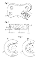
- FIG. 2 shows an enlarged section through the quick-change attachment according to FIG. 1 and
- the quick-change attachment component 10 shown in FIG. 1 is pivotally attached to a stalk, not shown, of the boom of a hydraulic excavator, for example.
- Quick-change attachment component 10 pivots in the familiar manner via a swiveling link plate, also not shown, about a pivot axis perpendicular to the longitudinal axis.
- Quick-change attachment component 10 has a bore hole 12 to accommodate a tool-connecting pin, not shown here.
- quick-change attachment component 10 has a bearing 14 in which another pin of the tool, not shown, is retained by positive fit or frictional engagement
- a bushing 16 is inserted in bearing 14 , bushing 16 being composed of a material which is more wear-resistant than the material of quick-change attachment component 10 .
- Bushing 16 is fixed within a bushing support region of bearing 14 , whereby this attachment may be implemented by an adhesive-bonding joint, shrink joint, welded joint, and/or screw connection, not shown in the figure.
- An essential aspect of the design of bushing 16 is the fact that it is formed by a half-liner having a large support angle ⁇ . This design ensures that the bushing is securely seated within the bushing support region.
- FIG. 2 shows an especially advantageous embodiment of bushing 16 .
- a collar 18 is integrally formed as part of the edge region of bushing 16 .
- the bushing support region here is created within quick-change attachment component 10 by a suitable bore hole in which the diameter of the bushing, and also of the collar, are recessed in a form-conforming manner.
- the bushing along with the collar in the edge region results in an increased strength and inherent stability which specifically provide improved strength in response to edge pressures.
- FIGS. 3 a and 3 b illustrate bushing designs in which bushings 16 are composed of half-liners fabricated from curved flat steel su 24 and 26 formed within the bushing support region of bearing 14 .
- FIGS. 3 a and 3 b show a symmetrical half-liner, whereas in FIG. 3 a the ends of the half-liner are extended by an amount L.
- the intervals required to regenerate the quick-change attachment, as well as costs thus incurred, may both be significantly reduced.
Landscapes
- Engineering & Computer Science (AREA)
- General Engineering & Computer Science (AREA)
- Mechanical Engineering (AREA)
- Mining & Mineral Resources (AREA)
- Civil Engineering (AREA)
- Structural Engineering (AREA)
- Earth Drilling (AREA)
- Component Parts Of Construction Machinery (AREA)
- Sliding-Contact Bearings (AREA)
Abstract
Description
Claims (21)
Applications Claiming Priority (2)
| Application Number | Priority Date | Filing Date | Title |
|---|---|---|---|
| DE10311927A DE10311927B4 (en) | 2003-03-18 | 2003-03-18 | Quick coupler |
| DE10311927.2 | 2003-03-18 |
Publications (2)
| Publication Number | Publication Date |
|---|---|
| US20040184875A1 US20040184875A1 (en) | 2004-09-23 |
| US7086804B2 true US7086804B2 (en) | 2006-08-08 |
Family
ID=32920899
Family Applications (1)
| Application Number | Title | Priority Date | Filing Date |
|---|---|---|---|
| US10/803,791 Expired - Lifetime US7086804B2 (en) | 2003-03-18 | 2004-03-18 | Quick-change attachment |
Country Status (3)
| Country | Link |
|---|---|
| US (1) | US7086804B2 (en) |
| DE (1) | DE10311927B4 (en) |
| FR (1) | FR2852615B1 (en) |
Cited By (2)
| Publication number | Priority date | Publication date | Assignee | Title |
|---|---|---|---|---|
| USD702738S1 (en) | 2011-07-01 | 2014-04-15 | Timothy M. Molnar | Attachment for equipment bucket |
| US20150117804A1 (en) * | 2013-10-30 | 2015-04-30 | United Technologies Corporation | Gas turbine engine bushing |
Families Citing this family (8)
| Publication number | Priority date | Publication date | Assignee | Title |
|---|---|---|---|---|
| US7984575B2 (en) | 2007-07-05 | 2011-07-26 | Caterpillar Inc. | Quick coupler assembly |
| US8974137B2 (en) | 2011-12-22 | 2015-03-10 | Caterpillar Inc. | Quick coupler |
| WO2013158472A1 (en) * | 2012-04-20 | 2013-10-24 | David Frost | Quick change mold system |
| US8869437B2 (en) | 2012-05-30 | 2014-10-28 | Caterpillar Inc. | Quick coupler |
| US8684623B2 (en) | 2012-05-30 | 2014-04-01 | Caterpillar Inc. | Tool coupler having anti-release mechanism |
| US9217235B2 (en) | 2012-05-30 | 2015-12-22 | Caterpillar Inc. | Tool coupler system having multiple pressure sources |
| US9228314B2 (en) | 2013-05-08 | 2016-01-05 | Caterpillar Inc. | Quick coupler hydraulic control system |
| CN107628585B (en) * | 2017-08-31 | 2024-03-19 | 广州达意隆包装机械股份有限公司 | Filling machine and bottle protection plate quick-change assembly thereof |
Citations (12)
| Publication number | Priority date | Publication date | Assignee | Title |
|---|---|---|---|---|
| FR2436743A1 (en) | 1978-09-25 | 1980-04-18 | Laan Roelof | Tool coupling mechanism to excavator boom - has intermediate piece between boom and control spindles coupled to tool adaptor |
| EP0321902A1 (en) | 1987-12-22 | 1989-06-28 | ZEPF, Hans-Rudolf | Tool-connecting device for an excavator |
| EP0353454A1 (en) | 1988-07-20 | 1990-02-07 | V.T.N. BENNE S.r.l. | Quick mount particularly for fixing buckets to earth-moving machines |
| US5082389A (en) * | 1987-06-04 | 1992-01-21 | Balemi William J | Connector with a spring-biased closure member |
| US5316709A (en) * | 1990-07-13 | 1994-05-31 | Samsung Heavy Industries Co., Ltd. | Method of making a dipper stick for an excavator from high strength polymeric composite materials |
| EP0616084A1 (en) | 1993-03-19 | 1994-09-21 | TREVI BENNE S.r.l. | Self-locking quick coupling for fitting buckets or the like to earth-movers |
| US5692852A (en) * | 1996-04-24 | 1997-12-02 | Entek Manufacturing Company | Quick connect system for excavator buckets |
| US5951192A (en) * | 1996-04-24 | 1999-09-14 | Entek Manufacturing, Inc. | Quick connect system for excavator buckets |
| US5983535A (en) | 1997-03-10 | 1999-11-16 | Clark Equipment Company | Fastener secured frame for boom mounted quick change bracket |
| US6132130A (en) * | 1995-10-06 | 2000-10-17 | Mccann; Noel Patrick Martin | Excavator hitch |
| US20020136597A1 (en) * | 2000-04-04 | 2002-09-26 | Hiroyasu Nishikawa | Quick coupler device of working machine |
| EP1312720A1 (en) | 2001-11-19 | 2003-05-21 | Mantovanibenne S.r.l. | Rapid tool coupling device |
-
2003
- 2003-03-18 DE DE10311927A patent/DE10311927B4/en not_active Expired - Lifetime
-
2004
- 2004-01-16 FR FR0400408A patent/FR2852615B1/en not_active Expired - Lifetime
- 2004-03-18 US US10/803,791 patent/US7086804B2/en not_active Expired - Lifetime
Patent Citations (12)
| Publication number | Priority date | Publication date | Assignee | Title |
|---|---|---|---|---|
| FR2436743A1 (en) | 1978-09-25 | 1980-04-18 | Laan Roelof | Tool coupling mechanism to excavator boom - has intermediate piece between boom and control spindles coupled to tool adaptor |
| US5082389A (en) * | 1987-06-04 | 1992-01-21 | Balemi William J | Connector with a spring-biased closure member |
| EP0321902A1 (en) | 1987-12-22 | 1989-06-28 | ZEPF, Hans-Rudolf | Tool-connecting device for an excavator |
| EP0353454A1 (en) | 1988-07-20 | 1990-02-07 | V.T.N. BENNE S.r.l. | Quick mount particularly for fixing buckets to earth-moving machines |
| US5316709A (en) * | 1990-07-13 | 1994-05-31 | Samsung Heavy Industries Co., Ltd. | Method of making a dipper stick for an excavator from high strength polymeric composite materials |
| EP0616084A1 (en) | 1993-03-19 | 1994-09-21 | TREVI BENNE S.r.l. | Self-locking quick coupling for fitting buckets or the like to earth-movers |
| US6132130A (en) * | 1995-10-06 | 2000-10-17 | Mccann; Noel Patrick Martin | Excavator hitch |
| US5692852A (en) * | 1996-04-24 | 1997-12-02 | Entek Manufacturing Company | Quick connect system for excavator buckets |
| US5951192A (en) * | 1996-04-24 | 1999-09-14 | Entek Manufacturing, Inc. | Quick connect system for excavator buckets |
| US5983535A (en) | 1997-03-10 | 1999-11-16 | Clark Equipment Company | Fastener secured frame for boom mounted quick change bracket |
| US20020136597A1 (en) * | 2000-04-04 | 2002-09-26 | Hiroyasu Nishikawa | Quick coupler device of working machine |
| EP1312720A1 (en) | 2001-11-19 | 2003-05-21 | Mantovanibenne S.r.l. | Rapid tool coupling device |
Cited By (2)
| Publication number | Priority date | Publication date | Assignee | Title |
|---|---|---|---|---|
| USD702738S1 (en) | 2011-07-01 | 2014-04-15 | Timothy M. Molnar | Attachment for equipment bucket |
| US20150117804A1 (en) * | 2013-10-30 | 2015-04-30 | United Technologies Corporation | Gas turbine engine bushing |
Also Published As
| Publication number | Publication date |
|---|---|
| US20040184875A1 (en) | 2004-09-23 |
| FR2852615A1 (en) | 2004-09-24 |
| DE10311927B4 (en) | 2007-06-28 |
| FR2852615B1 (en) | 2007-04-13 |
| DE10311927A1 (en) | 2004-10-14 |
Similar Documents
| Publication | Publication Date | Title |
|---|---|---|
| US7086804B2 (en) | Quick-change attachment | |
| EP1637661B1 (en) | Wear assembly | |
| SU1342428A3 (en) | Excavator bucket with edge | |
| US7730652B2 (en) | Wear assembly | |
| US8024874B2 (en) | Wear assembly for excavating machines | |
| US7637574B2 (en) | Pick assembly | |
| US5778570A (en) | Excavator tooth | |
| KR20010083121A (en) | Multipiece excavating tooth assembly | |
| KR20010071379A (en) | Device for the coupling of excavator teeth | |
| US6158917A (en) | Retention mechanism for mounting pins | |
| WO1998005827A1 (en) | Retention apparatus for a ground engaging tool | |
| CA2763729A1 (en) | Non-rotating washer for tool pick, tool and block assembly, method to reduce erosive wear and material removal machine | |
| CA2063083C (en) | Tooth assembly for a digger bucket | |
| US9782841B2 (en) | Cutting tool | |
| CA2149312C (en) | Attachment assembly for excavation teeth | |
| JP4046725B2 (en) | Hinged swivel teeth | |
| JP4526212B2 (en) | Drilling bit | |
| US6564482B2 (en) | Excavating apparatus with curved adapter/tooth point sliding pivotal interface area | |
| US20250137228A1 (en) | Pin retainer | |
| EP0197038A1 (en) | Corner tooth for a bucket. | |
| CN211948649U (en) | Composite alloy bucket tooth of excavator for mine | |
| US6141892A (en) | Apparatus for limiting chain wear | |
| NO177180B (en) | Interchangeable wear part | |
| RU2279524C1 (en) | Rock cutting tool | |
| JP4743594B2 (en) | Support structure for boom hoisting cylinder of hydraulic excavator |
Legal Events
| Date | Code | Title | Description |
|---|---|---|---|
| AS | Assignment |
Owner name: LIEBHERR-HYDRAULIKBAGGER GMBH, GERMANY Free format text: ASSIGNMENT OF ASSIGNORS INTEREST;ASSIGNORS:MIEGER, ROLF;ZITTERBART, THOMAS;REEL/FRAME:015124/0882 Effective date: 20040210 |
|
| STCF | Information on status: patent grant |
Free format text: PATENTED CASE |
|
| FEPP | Fee payment procedure |
Free format text: PAYOR NUMBER ASSIGNED (ORIGINAL EVENT CODE: ASPN); ENTITY STATUS OF PATENT OWNER: LARGE ENTITY |
|
| FPAY | Fee payment |
Year of fee payment: 4 |
|
| AS | Assignment |
Owner name: COOPERATIEVE CENTRALE RAIFFEISEN-BOERELEENBANK B.A Free format text: TERMINATION OF PATENT SECURITY AGREEMENT;ASSIGNOR:MAREL MEAT PROCESSING INC. (FKA STORK TOWNSEND INC.);REEL/FRAME:025521/0670 Effective date: 20101129 |
|
| AS | Assignment |
Owner name: MAREL MEAT PROCESSING INC. (F/K/A STORK TOWNSEND I Free format text: CORRECTIVE ASSIGNMENT TO CORRECT THE CONVEYING AND RECEIVING PARTIES PREVIOUSLY RECORDED ON REEL 025521 FRAME 0670. ASSIGNOR(S) HEREBY CONFIRMS THE TERMINATION OF PATENT SECURITY AGREEMENT;ASSIGNOR:COOPERATIVE CENTRALE RAIFFEISEN-BOERENLEEKBANK B.A.;REEL/FRAME:027817/0367 Effective date: 20101129 |
|
| FPAY | Fee payment |
Year of fee payment: 8 |
|
| MAFP | Maintenance fee payment |
Free format text: PAYMENT OF MAINTENANCE FEE, 12TH YEAR, LARGE ENTITY (ORIGINAL EVENT CODE: M1553) Year of fee payment: 12 |