US7075592B2 - Audio signal adjusting apparatus - Google Patents
Audio signal adjusting apparatus Download PDFInfo
- Publication number
- US7075592B2 US7075592B2 US10/367,369 US36736903A US7075592B2 US 7075592 B2 US7075592 B2 US 7075592B2 US 36736903 A US36736903 A US 36736903A US 7075592 B2 US7075592 B2 US 7075592B2
- Authority
- US
- United States
- Prior art keywords
- producing
- control signal
- location
- produced
- signal
- Prior art date
- Legal status (The legal status is an assumption and is not a legal conclusion. Google has not performed a legal analysis and makes no representation as to the accuracy of the status listed.)
- Expired - Fee Related, expires
Links
Images


Classifications
-
- H—ELECTRICITY
- H04—ELECTRIC COMMUNICATION TECHNIQUE
- H04S—STEREOPHONIC SYSTEMS
- H04S3/00—Systems employing more than two channels, e.g. quadraphonic
- H04S3/02—Systems employing more than two channels, e.g. quadraphonic of the matrix type, i.e. in which input signals are combined algebraically, e.g. after having been phase shifted with respect to each other
-
- A—HUMAN NECESSITIES
- A63—SPORTS; GAMES; AMUSEMENTS
- A63F—CARD, BOARD, OR ROULETTE GAMES; INDOOR GAMES USING SMALL MOVING PLAYING BODIES; VIDEO GAMES; GAMES NOT OTHERWISE PROVIDED FOR
- A63F2300/00—Features of games using an electronically generated display having two or more dimensions, e.g. on a television screen, showing representations related to the game
- A63F2300/60—Methods for processing data by generating or executing the game program
- A63F2300/6063—Methods for processing data by generating or executing the game program for sound processing
Definitions
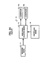
- FIG. 24 The conventional audio signal adjusting apparatus of this type is disclosed in the Publication of Japanese Patent No. 2906539. and shown in FIG. 24 .
- the conventional audio signal adjusting apparatus 10 is shown in FIG.
- the conventional audio signal adjusting apparatus 10 may further comprise a second display unit having a second screen to display an screen image indicative of the predetermined location of the imaginary sound source on the second screen. The operator, therefore, may judge whether or not the imaginary sound source appears to produce the audio sounds at the predetermined location requested by the operator based on the screen image displayed by the second display unit on the second screen.
- the conventional audio signal adjusting apparatus 10 requires at least two different operations consisting of judging and watching operations by an operator. The operator must judge whether or not the imaginary sound source appears to produce the audio sounds at the location requested by the operator under the condition that the raw audio sounds are respectively produced by the previously mentioned conventional audio signal adjusting apparatus in the judging operation.
- the operator is required to watch both the first and second screens on the former of which the screen image in association with the audio sounds is displayed by the first display unit and on the latter of which the location of the imaginary sound source is displayed by the second display unit in the watching operation. Furthermore, the operator finds it difficult to judge whether or not the imaginary sound source produces the audio sounds at the location requested by the operator under the condition that the raw audio sounds are respectively produced by the previously mentioned conventional audio signal adjusting apparatus while watching the first and second screens.
- an object of the present invention to provide an audio signal adjusting apparatus which can easily adjust the audio signals at a relatively high quality.
- an audio signal adjusting apparatus for respectively adjusting a plurality of raw audio signals each having a raw signal level to produce a plurality of adjusted audio signals each having an adjusted signal level, comprising: audio signal adjusting means for respectively adjusting the raw audio signals to produce the adjusted audio signals, and to be operably connected with a plurality of loudspeakers for respectively producing a plurality of audio sounds in a specific sound space, the audio sounds being respectively indicative of the adjusted audio signals, and collectively originated from at least one imaginary sound source having a width, the imaginary sound source being imagined to produce the audio sounds at a location spaced apart from each of the loudspeakers; location control signal producing means for producing a location control signal indicative of the location of the imaginary sound source; controlling means for controlling the audio signal adjusting means to allow each of the raw audio signals to be adjusted by the audio signal adjusting means in response to the location control signal produced by the location control signal producing means; pointer image producing means for producing a pointer image indicative of the location of the imaginary sound source; and
- an audio signal adjusting apparatus for respectively adjusting a plurality of raw audio signals each having a raw signal level to produce a plurality of adjusted audio signals each having an adjusted signal level, comprising: a plurality of loudspeakers for respectively producing a plurality of audio sounds in a specific sound space, the audio sounds being respectively indicative of the adjusted audio signals, and collectively originated from at least one imaginary sound source having a width, the imaginary sound source being imagined to produce the audio sounds at a location spaced apart from each of the loudspeakers; location control signal producing means for producing a location control signal indicative of the location of the imaginary sound source; audio signal adjusting means for respectively adjusting the raw audio signals to produce the adjusted audio signal to be outputted to each of the loudspeakers; controlling means for controlling the audio signal adjusting means to allow each of the raw audio signals to be adjusted by the audio signal adjusting means in response to the location control signal produced by the location control signal producing means; a video signal input terminal having a video signal in association with each of the raw
- the audio signal adjusting apparatus may further comprise deciding means for deciding whether or not the pointer image produced by the pointer image producing means is superimposed by the superimposing means on the portion of the screen image to be displayed by the display means on the screen, the superimposing means being operative to superimpose the pointer image produced by the pointer image producing means on the portion of the screen image to be displayed by the display means on the screen based on results decided by the deciding means.
- the audio signal adjusting apparatus may further comprise audio signal recording means operably connected with video signal recording means having an operation timing to record the video signal received through the video signal input terminal, and designed to record the adjusted audio signals adjusted by the audio signal adjusting means in synchronization with the operation timing of the video signal recording means.
- the controlling means may include a control signal converting unit for respectively converting the location control signal produced by the location control signal producing means and the width control signal produced by the width control signal producing means to location information indicative of the location of the imaginary sound source and width information indicative of the width of the imaginary sound source, a signal level ratio producing unit for producing a signal level ratio of each of the adjusted signal levels of the adjusted audio signals to each of the raw signal levels of the raw audio signals based on the location information and the width information converted by the control signal converting unit, and a delay time information producing unit for producing delay time information with respect to a delay time for each of the raw audio signals based on the location information and the width information received from the control signal converting unit; and the audio signal adjusting means including a plurality of signal level adjusting unit for respectively adjusting the raw signal levels of the raw audio signals based on the signal level ratio of each of the adjusted signal levels of the adjusted audio signals to each of the raw signal levels of the raw audio signals produced by the signal level ratio producing unit, and a plurality of delay unit for respectively delaying the raw
- the pointer image producing means may include a pointer image producing unit for producing the pointer image having a shape indicative of the width of the imaginary sound source and a pointer image modifying unit for modifying the shape of the pointer image produced by the pointer image producing unit in response to each of the location control signal produced by the location control signal producing means and the width control signal produced by the width control signal producing means; and the superimposing means being operative to superimpose the pointer image modified by the pointer image modifying unit on the portion of the screen image to be displayed by the display means on the screen.
- the pointer image producing unit may be operative to produce the pointer image having a color in association with the location of the imaginary sound source; the pointer image modifying unit being operative to modify the color of the pointer image produced by the pointer image producing unit in response to the location control signal produced by the location control signal producing means; and the superimposing means being operative to superimpose the pointer image modified by the pointer image modifying unit on the portion of the screen image to be displayed by the display means on the screen.
- the audio signal adjusting apparatus may further comprise first scale information producing means for producing a first scale information about an adjustment for the location control signal; storing means for storing the first scale information produced by the first scale information producing means; and judging means for judging whether or not the first scale information produced by the first scale information producing means are stored by the storing means, and the storing means being operative to store the first scale information produced by the first scale information producing means based on results judged by the judging means.
- the signal level ratio producing unit may be operative to produce the signal level ratio of each of the adjusted signal levels of the adjusted audio signals to each of the raw signal levels of the raw audio signals based on the location information and the width information received from the control signal converting unit; and the delay time information producing unit being operative to produce the delay time information with respect to the delay time for each of the raw audio signals based on the location information and the width information received from the control signal converting unit.
- the first scale information producing means may be constituted by a first joystick unit having a joystick and an operation surface, the joystick having a central axis and a central point located on the central axis, and the joystick being pivotable around the central axis at a variable inclination angle between the central axis and the operation surface in association with first scale information, and the first joystick unit being operative to produce the first scale information in response to the inclination angle;
- the location control signal producing means being constituted by a second joystick unit having a joystick and an operation surface, the joystick having a central axis and a central point located on the central axis, and the joystick being pivotable around the central axis at a variable inclination angle between the central axis and the operation surface in association with the location of the imaginary sound source, and the first joystick unit being operative to produce the location control signal in response to the inclination angle;
- the pointer image producing means being operative to produce the pointer image through steps of producing the pointer image
- FIG. 3 is a block diagram of the audio signal adjusting means forming part of the audio signal adjusting apparatus according to the preferred embodiment of the present invention
- FIG. 5 is a schematic diagram showing the specific sound space in which the audio sounds are respectively produced by the loudspeakers each forming part of the audio signal adjusting apparatus according to the preferred embodiment of the present invention
- FIG. 7 is a schematic diagram showing the screen image on which each of the pointer image and the chart image is superimposed by the superimposing means forming part of the audio signal adjusting apparatus according to the preferred embodiment of the present invention
- FIG. 8 is a schematic diagram showing the screen image on which the pointer image is superimposed by the superimposing means forming part of the audio signal adjusting apparatus according to the preferred embodiment of the present invention
- FIG. 10 is a schematic diagram showing the predetermined normal distribution function allowing the signal coefficients to be respectively produced by the signal level ratio producing unit forming part of the audio signal adjusting apparatus according to the preferred embodiment of the present invention
- FIG. 11 is a plan view showing the loudspeakers forming part of the audio signal adjusting apparatus according to the preferred embodiment of the present invention, the loudspeakers being respectively disposed on a plurality of circumferential lines in the specific sound space,
- FIG. 12 is a schematic diagram showing the portion of the screen image on which the pointer image is superimposed by the superimposing means forming part of the audio signal adjusting apparatus according to the preferred embodiment of the present invention
- FIG. 13 is a schematic diagram showing the screen image on which the pointer image is superimposed by the superimposing means forming part of the audio signal adjusting apparatus according to the preferred embodiment of the present invention
- FIG. 14 is a schematic diagram showing the database with respect to the location information stored by the storing means forming part of the audio signal adjusting apparatus according to the preferred embodiment of the present invention.
- FIG. 15 is a schematic diagram showing the specific sound space in which the audio sounds are respectively produced by the loudspeakers each forming part of the audio signal adjusting apparatus according to the preferred embodiment of the present invention
- FIG. 16 is a schematic diagram showing the specific sound space in which the audio sounds are respectively produced by the loudspeakers each forming part of the audio signal adjusting apparatus according to the preferred embodiment of the present invention
- FIG. 17 is a schematic diagram showing the database with respect to the location information stored by the storing means forming part of the audio signal adjusting apparatus according to the preferred embodiment of the present invention.
- FIG. 21 is a schematic diagram showing the database with respect to the width information stored by the storing means forming part of the audio signal adjusting apparatus according to the preferred embodiment of the present invention.
- FIG. 22 is a schematic diagram showing the width information which is produced by the control signal converting unit forming part of the audio signal adjusting apparatus according to the preferred embodiment of the present invention.
- FIG. 24 is a block diagram of the conventional audio signal adjusting apparatus.
- an audio signal adjusting apparatus 100 for respectively adjusting a plurality of raw audio signals to produce a plurality of adjusted audio signals, each of the raw audio signals having an raw phase angle and an raw signal level, and each of the adjusted audio signals having an adjusted phase angle and an adjusted signal level.
- the loudspeakers 111 , 112 , . . . , and 113 are respectively disposed on a circumferential line of a predetermined circle having a central location 201 in the specific sound space.
- the image screen 210 has a predetermined location spaced apart from the central location 201 .
- the display means 142 is constituted by a video projector to display the video image on the image screen 210 .
- the audio signal adjusting means 120 is operative to respectively adjust the raw audio signals to produce the adjusted audio signals, each of the raw audio signals having a raw phase angle and a raw signal level, each of the adjusted audio signals having an adjusted phase angle and an adjusted signal level; the controlling means 170 including an control signal converting unit 171 for respectively converting the location control signal produced by the location control signal producing means 151 and the width control signal produced by the width control signal producing means 152 to location information indicative of the location of the imaginary sound source and width information indicative of the width of the imaginary sound source, a signal level ratio producing unit 172 for producing a signal level ratio of each of the adjusted signal levels of the adjusted audio signals to each of the raw signal levels of the raw audio signals based on the location information and the width information converted by the control signal converting unit 171 , and a delay time information producing unit 173 for producing delay time information with respect to a delay time for each of the raw audio signals based on the location information and the width information received from the control signal converting unit 170 .
- the controlling means 170 including an
- the signal level ratio producing unit 172 is operative to produce the signal level ratio of each of the adjusted signal levels of the adjusted audio signals to each of the raw signal levels of the raw audio signals based on the location information (d, ⁇ ) converted by the control signal converting unit 171 and the width information “w” converted by the control signal converting unit 171 .
- the audio signal adjusting apparatus 100 further comprises first scale information producing means 161 for producing a first scale information about an adjustment of the location control signal; second scale information producing means 162 for producing a second scale information about an adjustment of the width control signal; storing means 180 for storing each of the first scale information produced by the first scale information producing means 161 and the second scale information produced by the second scale information producing means 162 ; and judging means 163 for judging whether or not the first scale information produced by the first scale information producing means 161 are stored by the storing means 180 , the storing means 180 being operative to store the first scale information produced by the first scale information producing means 161 based on results judged by the judging means 163 .
- the first scale information producing means 161 is constituted by a first joystick unit 161 having a joystick and an operation surface, the joystick having a central axis and a central point located on the central axis, and the joystick being pivotable around the central axis at a variable inclination angle between the central axis and the operation surface in association with first scale information, and the first joystick unit being operative to produce the first scale information in response to the inclination angle;
- the location control signal producing means 151 being constituted by a second joystick unit 151 having a joystick and an operation surface, the joystick having a central axis and a central point located on the central axis, and the joystick being pivotable around the central axis at a variable inclination angle between the central axis and the operation surface in association with the location of the imaginary sound source, and the first joystick unit 151 being operative to produce the location control signal in response to the inclination angle;
- the pointer image producing means 130 being operative to produce the point
- the width control signal producing means 152 is constituted by a first potentiometer 152 having a rotatable central axis, the first potentiometer 152 being operative to produce the width control signal varied in response to a rotation angle of the central axis;
- the second scale information producing means 162 being constituted by a second potentiometer 162 having a rotatable central axis, the second potentiometer 162 being operative to produce the second scale information varied in response to a rotation angle of the central axis;
- the pointer image producing means 130 being operative to produce the pointer image through steps of producing the pointer image in response to the width control signal produced by the first potentiometer 152 , and adjusting the pointer image in response to the second scale information produced by the second potentiometer 162 when the second scale information is produced by the second potentiometer 162 under the condition that the central axis of the first potentiometer 152 is disposed at a predetermined rotation angle; and the audio signal adjusting means 120
- the location control signal producing means 151 , the width control signal producing means 152 , and deciding means 153 are respectively constituted by the first joystick unit 151 , the second potentiometer 152 , and a first switch 153 .
- the first joystick unit 151 , the second potentiometer 152 , and the first switch 153 are collectively constitute a first inputting means 150 .
- the first scale information producing means 161 , the second scale information producing means 162 , and the judging means 163 are respectively constituted by the second joystick unit 161 , the first potentiometer 162 , and a second switch 163 .
- the second joystick unit 161 , the first potentiometer 162 , and the second switch 163 are collectively constitute a second inputting means 160 .
- the first joystick unit 151 forming part of the first inputting means 150 is the same as the second joystick unit 161 forming part of second inputting means 160 .
- the first controller 152 forming part of the first inputting means 150 is the same as the second controller 162 forming part of second inputting means 160 .
- FIG. 6 shows the screen image displayed on the screen by the display means 142 forming part of the audio signals adjusting means 100 according to the preferred embodiment of the present invention.
- the display means 142 is operative to display the screen image on the screen after receiving the video signal having the screen image from the video signal producing means 102 through the video signal input terminal 103 .
- FIG. 8 is a schematic diagram showing the screen image on which the pointer image is superimposed by the superimposing means forming part of the audio signal adjusting apparatus according to the preferred embodiment of the present invention.
- the pointer image producing means 130 includes a pointer image producing unit 131 for producing the pointer image having a shape indicative of the width of the imaginary sound source and a pointer image modifying unit 132 for modifying the shape of the pointer image produced by the pointer image producing unit 131 in response to each of the location control signal produced by the location control signal producing means 151 and the width control signal produced by the width control signal producing means 152 ; and the superimposing means 141 , as shown in FIG. 8 , being operative to superimpose the pointer image modified by the pointer image modifying unit 132 on the portion of the screen image to be displayed by the display means 142 on the screen 210 .
- the pointer image producing unit 131 is operative to produce the pointer image having a color in association with the location of the imaginary sound source; the pointer image modifying unit 132 being operative to modify the color of the pointer image produced by the pointer image producing unit 131 in response to the location control signal produced by the location control signal producing means 151 ; and the superimposing means 141 being operative to superimpose the pointer image modified by the pointer image modifying unit 132 on the portion of the screen image to be displayed by the display means 142 on the screen 210 .
- the pointer image producing unit 131 is operative to produce the pointer image based on the location information (d, ⁇ ) converted by the control signal converting unit 171 , the width information “w” converted by the control signal converting unit 171 , and each of the first scale information and the second scale information stored by the storing means 180 ; the chart image producing means 140 being operative to produce the chart image based on the location information converted by the control signal converting unit 171 , the width information converted by the control signal converting unit 171 , and each of the first scale information and the second scale information stored by the storing means 180 .
- FIG. 7 shows the screen image on which each of the pointer image 711 and the chart image 720 is superimposed by the superimposing means 141 .
- the chart image 720 as shown in FIG. 7 , has a radar chart indicative of the specific sound space, the radar chart having a circumferential line on which each of the loudspeakers 111 , 112 , . . .
- a plurality of concentric circles collectively having a common central point indicative of the predetermined central location of the specific sound space, a plurality of straight lines each extending to pass through the common central point of the concentric circles, and a marker indicative of the imaginary sound source, the marker having a source shape indicative of the width of the imaginary sound source, a source point indicative of the location of the imaginary sound source.
- the location control signal indicative of the location of the imaginary sound source and the width control signal indicative of the width of the imaginary sound source are firstly respectively produced by the location control signal producing means 151 and the width control signal producing means 152 in the step S 001 .
- the signal level ratio of the adjusted signal level of each of the adjusted audio signals to the raw signal level of each of the raw audio signals (hereinafter referred to simply as “signal coefficients”) and the delay time information for each of the raw audio signals are then respectively produced by the signal level ratio producing unit 172 and the delay time information producing unit 173 based on the location information and the width information converted by the control signal converting unit 171 in the step S 003 .
- the raw signal levels of the raw audio signals are then respectively adjusted by each of the signal level adjusting units 121 and the delay unit 122 to produce the adjusted signal levels of the adjusted audio signals based on the signal coefficients produced by the signal level ratio producing unit 172 and delay time information for each of the raw audio signals delay time information producing unit 173 while the adjusted audio signals adjusted by the audio signal adjusting means 120 are respectively recorded by the audio signal recording means 191 in synchronization with the operation timing of the video signal recording means 192 in the step S 004 .
- the audio sounds are then respectively produced by the loudspeakers 111 , 112 , . . . , and 113 in response to the adjusted audio signals adjusted by the audio signal adjusting means 120 in the step S 005 .
- the pointer image indicative of the imaginary sound source is then produced by the pointer image producing unit 131 in response to each of the location information (d, ⁇ ) and width information “w” converted by the control signal converting unit 171 , the color and the shape of the pointer image produced by the pointer image producing unit 131 being then respectively modified by the pointer image modifying unit 132 in response to each of the location information (d, ⁇ ) and width information “w” converted by the control signal converting unit 171 .
- the chart image indicative of the specific sound space is then produced by the chart image producing means 140 in response to the location information (d, ⁇ ) converted by the control signal converting unit 171 , the width information “w” converted by the control signal converting unit 171 , and each of the first scale information and the second scale information stored by the storing means 180 in the step S 006 .
- step S 007 proceeds the step S 008 .
- step S 007 When the answer in the step S 007 , on the other hand, is the negative “NO”, i.e., each of the pointer image produced by the pointer image producing unit 131 and the chart image produced by the chart image producing means 140 is not superimposed by the superimposing means 141 on the predetermined portion of the screen image to be displayed by the display means 142 on the screen, the step S 007 goes to the step S 001 .
- the pointer image produced by the pointer image producing unit 131 and the chart image produced by the chart image producing means 140 are then respectively superimposed by the superimposing means 141 the screen image to be displayed by the display means 142 on the screen based on results decided by the deciding unit 133 in the step S 008 .
- step S 003 performed by the audio signal adjusting apparatus 100 according to the preferred embodiment of the present invention.
- the baseline 902 extending to pass through the central location 900 is firstly obtained by the signal level ratio producing unit ( 172 ) in response to the location information (d, ⁇ ) converted by the control signal converting unit ( 171 ).
- the loudspeakers 911 , 912 , 913 , 922 , 923 , 931 , 932 , 933 , 941 , 942 , . . . , and 943 is then divided into two different groups consisting of first and second groups based on the baseline obtained by the signal level ratio producing unit ( 172 ), the first group including loudspeakers 911 , 912 , 913 , 941 , 942 , . . . , and 943 , the second group including loudspeakers 921 , 922 , 923 , 931 , 932 , . . . , and 933 .
- the combination of the loudspeakers (Sa[ 1 ], Sb[ 1 ]), (Sa[ 2 ], Sb[ 2 ]), . . . , and (Sa[i], Sb[i]) are then respectively obtained by the signal level ratio producing unit ( 172 ) based on the first group and the second group.
- the combination of the loudspeakers (Sc[ 1 ], Sd[ 1 ]), (Sc[ 2 ], Sd[ 2 ]), . . . , and (Sc[i], Sd[i]) are then respectively obtained by the signal level ratio producing unit ( 172 ) based on the first group and the second group.
- the direction angle between the baseline 902 and the straight line connecting the central location 900 and the location of each of the loudspeakers 911 , 912 , 913 , 922 , 923 , 931 , 932 , 933 , 941 , 942 , . . . , and 943 is then obtained by the signal level ratio producing unit ( 172 ).
- the direction angles of the loudspeakers (Sa[ 1 ], Sb[ 1 ]), (Sa[ 2 ], Sb[ 2 ]), . . . , and (Sa[i], Sb[i]) are respectively represented by the legends ( ⁇ a[ 1 ], ⁇ b[ 1 ]), ( ⁇ a[ 2 ], ⁇ b[ 2 ]), . . . and ( ⁇ a[i], ⁇ b[i]).
- the direction angles of the loudspeakers (Sc[ 1 ], Sd[ 1 ]), (Sc[ 2 ], Sd[ 2 ]), . . .
- the first signal coefficients (Pa[ 1 ], Pb[ 1 ]), (Pa[ 2 ], Pb[ 2 ]), . . . and (Pa[i], Pb[i]) are, as shown in FIG. 10 , then respectively obtained by the signal level ratio producing unit ( 172 ) based on the direction angles ( ⁇ a[ 1 ], ⁇ b[ 1 ]), ( ⁇ a[ 2 ], ⁇ b[ 2 ]), . . . and ( ⁇ a[i], ⁇ b[i]) and the predetermined normal distribution function.
- the first total amount “Pab” of the first signal coefficients (Pa[ 1 ], Pb[ 1 ]), (Pa[ 2 ], Pb[ 2 ]), . . . and (Pa[i], Pb[i]) and the second total amount “Pcd” of the second signal coefficients (Pc[ 1 ], Pd[ 1 ]), (Pc[ 2 ], Pd[ 2 ]), . . . and (Pc[i], Pd[i]) are then respectively obtained by the signal level ratio producing unit ( 172 ), each of the first signal coefficients (Pa[ 1 ], Pb[ 1 ]), (Pa[ 2 ], Pb[ 2 ]), . . .
- Pab: Pcd 1: ( r max ⁇ d )/ r max (equation 1)
- the signal coefficients are finally produced by the signal level ratio producing unit ( 172 ) under the condition that the total amount v out [decibel] of the power values of the adjusted audio signals is equal to the total amount V in [decibel] of the power values of the raw audio signals, i.e., the following equation 2.
- M is equal to the total number of the loudspeakers 911 , 912 , 913 , 922 , 923 , 931 , 932 , 933 , 941 , 942 , . . . , and 943 .
- the delay time t[j] is obtained by the delay time information producing unit 173 by using the following equation 3 under the condition that the loudspeakers are respectively disposed on the circumferential line of the circle having the radius “r max ”.
- t[j ] ( r max ⁇ r[j] )/ v 0 (equation 3)
- the legend “r[j]” is indicative of the distance between the central location 1100 and the location of the loudspeaker 1110
- the legend “v 0 ” is indicative of the sound velocity.
- step S 006 performed by the audio signal adjusting apparatus 100 according to the preferred embodiment of the present invention.
- the portion of the screen image on which the pointer image is superimposed the superimposing means 141 is shown in FIG. 12 . It is assumed that the screen 210 having a width “sw” is disposed at the location spaced apart from the central location 200 of the specific sound space.
- the position 1201 in association with the location of the imaginary sound source is firstly calculated by the superimposing means 141 based on the location information (d, ⁇ ), the pointer image is then superimposed by the superimposing means 141 on the portion of the screen image to be displayed by the display means 142 based on the position 1201 .
- the width of the pointer image is obtained by the pointer image producing means 130 by multiplying the ratio of the distance “d” between the central location 201 and the location of the imaginary sound source to the distance between the central location 201 and the position 1201 by the width “w” of the imaginary sound source.
- the following description will be directed to the first scale information produced by the first scale information producing means 161 forming part of the audio signal adjusting apparatus 100 according to the preferred embodiment of the present invention with no flowchart.
- FIG. 14 is a schematic diagram showing the database with respect to the location information stored by the storing means forming part of the audio signal adjusting apparatus according to the preferred embodiment of the present invention.
- FIG. 15 is a schematic diagram showing the specific sound space in which the audio sounds are respectively produced by the loudspeakers each forming part of the audio signal adjusting apparatus according to the preferred embodiment of the present invention.
- the signal levels of the raw audio sounds are then respectively adjusted by the signal level adjusting unit 121 based on the signal coefficients produced by the signal level ratio producing unit 172 , the raw phase angles of the raw audio sounds being respectively adjusted by the delay unit 122 based on the phase differences produced by the delay time information producing unit 173 .
- the pointer image is produced by the pointer image producing means 131 based on the location information (R max , 0) converted by the control signal converting unit 171 , and superimposed by the superimposing means 130 on the screen image.
- the first scale information is then produced by the first scale information producing means 161 .
- the location control signal is then converted by the control signal converting unit 171 to the location information (d 1 , ⁇ 1 ) in response to the first scale information produced by the first scale information producing means 161 .
- the signal coefficients are then respectively produced by the signal level ratio producing unit 172 in response to the location information (d 1 , ⁇ 1 ), the phase differences being respectively produced by the delay time information producing unit 173 in response to the location information (d 1 , ⁇ 1 ).
- the raw signal levels of the raw audio sounds are then respectively adjusted by the signal level adjusting unit 121 based on the signal coefficients produced by the signal level ratio producing unit 172 , the phase angles of the raw audio sounds being respectively adjusted by the delay unit 121 based on the phase differences produced by the delay time information producing unit 173 .
- the first scale information is then produced by the first scale information producing means 161 .
- the location control signal is then converted by the control signal converting unit 171 to the location information (d 2 , ⁇ 2 ) in response to the first scale information produced by the first scale information producing means 161 .
- the pointer image is then produced by the pointer image producing unit 131 in response to the location information (d 2 , ⁇ 2 ) converted by the control signal converting unit 171 , and superimposed by the superimposing means 130 on the screen image to be displayed on the screen 210 .
- the judging means 163 When the judgment is made by the judging means 163 that the location information (d 0 , ⁇ 0 ), (d 1 , ⁇ 1 ), and (d 2 , ⁇ 2 ) is respectively stored by the storing means 180 , the location information (d 0 , ⁇ 0 ), (d 1 , ⁇ 1 ), and (d 2 , ⁇ 2 ) being finally stored by the storing means 180 , the location information (d 0 , ⁇ 0 ), (d 1 , ⁇ 1 ), and (d 2 , ⁇ 2 ) stored by the storing means 180 , as shown in FIGS. 14 and 15 , collectively constituting a database 1400 with respect to the location information (d 0 , ⁇ 0 ), (d 1 , ⁇ 1 ), and (d 2 , ⁇ 2 ).
- the location control signal is, practically, firstly produced by the location control signal producing means 151 while the location control signal is converted by the control signal converting unit 171 to the location information (d x , ⁇ x ), the location information (d 0 , ⁇ 0 ) being selected by the control signal converting unit 171 from the database with respect to the location information (d 0 , ⁇ 0 ), (d 1 , ⁇ 1 ), and (d 2 , ⁇ 2 ) in response to the location information (d x , ⁇ x ).
- FIG. 17 is a schematic diagram showing the database 1700 with respect to the location information stored by the storing means forming part of the audio signal adjusting apparatus according to the preferred embodiment of the present invention.
- the location information (d 1 , ⁇ 1 ) is ,as shown in FIG. 18 , calculated by the control signal converting means 171 from the location information (d 1A , ⁇ 1A ), (d 1B , ⁇ 1B ), (d 1C , ⁇ 1C ), and (d 1D , ⁇ 1D ) stored by the storing means 180 , the location information (d 2 , ⁇ 2 ) being calculated by based on the location information (d 2A , ⁇ 2A ), (d 2B , ⁇ 2B ), (d 2C , ⁇ 2C ), and (d 2D , ⁇ 2D ) stored by the storing means 180 .
- the signal coefficients are finally respectively produced by the signal level ratio producing unit 172 based on the location information (d 1 , ⁇ 1 ) calculated by the control signal converting means 171 , the phase differences being respectively produced by the delay time information producing unit 173 based on the location information (d 1 , ⁇ 1 ) calculated by the control signal converting means 171 , the pointer image is produced by the pointer image producing unit 131 based on the location information (d 1 , ⁇ 1 ).
- the raw signal levels of the raw audio sounds are then respectively adjusted by the signal level adjusting unit 121 based on the signal coefficients produced by the signal level ratio producing unit 172 , the raw phase angles of the raw audio sounds being respectively adjusted by the delay unit 122 based on the phase differences produced by the delay time information producing unit 173 .
- the second scale information is then produced by the second scale information producing means 162 .
- the raw signal levels of the raw audio sounds are then respectively adjusted by the signal level adjusting unit 121 based on the signal coefficients produced by the signal level ratio producing unit 172 , the phase angles of the raw audio sounds being respectively adjusted by the delay unit 121 based on the phase differences produced by the delay time information producing unit 173 .
- the second scale information is then produced by the second scale information producing means 162 .
- the width control signal is then converted by the control signal converting unit 171 to the width information “w 2 ” in response to the second scale information produced by the second scale information producing means 162 .
- the pointer image is then produced by the pointer image producing unit 131 in response to the width information “w 2 ” converted by the control signal converting unit 171 , and superimposed by the superimposing means 130 on the screen image to be displayed on the screen 210 .
- the width information “w 0 ”, “w 1 ”, and “w 2 ” is respectively stored by the storing means 180 , the width information “w 0 ”, “w 1 ”, and “w 2 ” being finally stored by the storing means 180 , the location information “w 0 ”, “w 1 ”, and “w 2 ” stored by the storing means 180 , as shown in FIGS. 19 and 20 , collectively constituting a database 1400 with respect to the location information “w 0 ”, “w 1 ”, and “w 2 ”.
- the width control signal is firstly produced by the width control signal producing means 152 while the width control signal is converted by the control signal converting unit 171 to the width information “w x ”, the width information “w 0 ” being selected by the control signal converting unit 171 from the database with respect to the width information “w 0 ”, “w 1 ”, and “w 2 ” in response to the width information “w x ”.
- the signal coefficients are then respectively produced by the signal level ratio producing unit 172 based on the width information “w 1 ” selected by the second scale information producing mean 172 , the phase differences being respectively produced by the delay time information producing unit 173 based on the width information “w 1 ” selected by the second scale information producing mean 172 .
- FIG. 17 is a schematic diagram showing the database 1700 with respect to the width information stored by the storing means forming part of the audio signal adjusting apparatus according to the preferred embodiment of the present invention.
- the width information “w 1 ” is, as shown in FIG. 22 , calculated by the control signal converting means 171 from the width information “w A ”, “w B ”, “w C ”, and “w D ” stored by the storing means 180 , the width information “w 2 ” being calculated by based on the width information “w A ”, “w B ”, “w C ”, and “w D ” stored by the storing means 180 .
- the signal coefficients are finally respectively produced by the signal level ratio producing unit 172 based on the width information “w 1 ” calculated by the control signal converting means 171 , the phase differences being respectively produced by the delay time information producing unit 173 based on the width information “w 1 ” calculated by the control signal converting means 171 , the pointer image is produced by the pointer image producing unit 131 based on the width information “w 2 ”.
- the audio signal adjusting apparatus can easily adjust the raw audio signals at a relatively high quality in response to the location control signal by the reason that the audio signal adjusting apparatus 100 comprises location control signal producing means 151 for producing the location control signal indicative of the location of the imaginary sound source; audio signal adjusting means 120 for adjusting each of the raw audio signals to produce the adjusted audio signal to be outputted to each of the loudspeakers; controlling means 170 for controlling the audio signal adjusting means 120 to allow each of the raw audio signals to be adjusted by the audio signal adjusting means 120 in response to the location control signal produced by the location control signal producing means 151 , pointer image producing means 130 for producing a pointer image indicative of the location of the imaginary sound source; and superimposing means 141 for superimposing the pointer image produced by the pointer image producing means 130 on the portion of the screen image to be displayed by the display means 142 on the screen in response to the location control signal produced by the location control signal producing means 151 .
- the audio signal adjusting apparatus can easily adjust the raw audio signals at a relatively high quality in response to the width control signal by the reason that the audio signal adjusting apparatus 100 further comprises width control signal producing means 152 for producing the width control signal indicative of the location of the imaginary sound source, the controlling means 170 being operative to control the audio signal adjusting means 120 to allow each of the raw audio signals to be adjusted by the audio signal adjusting means 120 in response to each of the location control signal produced by the location control signal producing means 151 and the width control signal produced by the width control signal producing means 152 , pointer image producing means being operative to produce the pointer image having a shape indicative of the width of the imaginary sound source, the superimposing means 141 being operative to superimpose the pointer image produced by the pointer image producing means 130 on the portion of the screen image to be displayed by the display means 142 on the screen.
- the audio signal adjusting apparatus can easily adjust the raw audio signals at a relatively high quality in response to each of the location control signal and the width control signal by the reason that the audio signal adjusting apparatus 100 further comprises deciding means 153 for deciding whether or not the pointer image produced by the pointer image producing means 130 is superimposed by the superimposing means 141 on the portion of the screen image to be displayed by the display means 142 on the screen, the superimposing means 141 being operative to superimpose the pointer image produced by the pointer image producing means 130 on the portion of the screen image to be displayed by the display means 142 on the screen based on results decided by the deciding means 153 .
- This leads to the fact that the audio sounds respectively produced by the loudspeakers are collectively originated from at least one imaginary sound source, the imaginary sound source being imagined to produce the audio sounds at a location requested by the operator.
- the audio signal adjusting apparatus can easily adjust the raw audio signals at a relatively high quality in response to each of the location control signal and the width control signal by the reason that the audio signal adjusting apparatus 100 further comprises audio signal recording means 191 operably connected with video signal recording means 192 having an operation timing to record the video signal produced by the video signal producing means 102 , and designed to record the adjusted audio signals adjusted by the audio signal adjusting means 120 in synchronization with the operation timing of the video signal recording means 192 .
- the audio signal adjusting apparatus can easily adjust the raw audio signals at a relatively high quality in response to each of the location control signal and the width control signal by the reason that the controlling means 170 includes an control signal converting unit 171 for respectively converting the location control signal produced by the location control signal producing means 151 and the width control signal produced by the width control signal producing means 152 to location information indicative of the location of the imaginary sound source and width information indicative of the width of the imaginary sound source, a signal level ratio producing unit 172 for producing a signal level ratio of each of the adjusted signal levels of the adjusted audio signals to each of the raw signal levels of the raw audio signals based on the location information and the width information converted by the control signal converting unit 171 , and a delay time information producing unit 173 for producing a phase difference between each of the raw phase angles of the raw audio signals and each of the adjusted phase angles of the adjusted audio signals based on the location information and the width information converted by the control signal converting unit 171 ; and the audio signal adjusting means 120 includes a plurality
- the audio signal adjusting apparatus can easily adjust the raw audio signals at a relatively high quality in response to each of the location control signal and the width control signal by the reason that the audio signal adjusting apparatus 100 further comprises a chart image producing means 140 for producing a chart image indicative of the specific sound space having a predetermined central location and a first distance between the predetermined central location and the location of the imaginary sound source, the chart image having two different points consisting of first and second points, the first point being indicative of the predetermined central location of the specific sound space, the second point being indicative of the location of the imaginary sound source, a second distance between the first point and the second point, and in which the screen image to be displayed by the display means 142 on the screen has a predetermined portion, a marker indicative of the imaginary sound source, and the marker having a shape indicative of the width of the imaginary sound source, the superimposing means 141 being operative to superimpose the chart image produced by the chart image producing means 140 on the predetermined portion of the screen image to be displayed by the display means 142 on the
- the audio signal adjusting apparatus can easily adjust the raw audio signals at a relatively high quality in response to each of the location control signal and the width control signal by the reason that the pointer image producing means 130 includes a pointer image producing unit 131 for producing the pointer image having a shape indicative of the width of the imaginary sound source and a pointer image modifying unit 132 for modifying the shape of the pointer image produced by the pointer image producing unit 131 in response to each of the location control signal produced by the location control signal producing means 151 and the width control signal produced by the width control signal producing means 152 ; and the superimposing means 141 is operative to superimpose the pointer image modified by the pointer image modifying unit 132 on the portion of the screen image to be displayed by the display means 142 on the screen 210 .
- the audio signal adjusting apparatus can easily adjust the raw audio signals at a relatively high quality in response to each of the location control signal and the width control signal by the reason that the pointer image producing unit 131 is operative to produce the pointer image having a color in association with the location of the imaginary sound source; the pointer image modifying unit 132 is operative to modify the color of the pointer image produced by the pointer image producing unit 131 in response to the location control signal produced by the location control signal producing means 151 ; and the superimposing means 141 is operative to superimpose the pointer image modified by the pointer image modifying unit 132 on the portion of the screen image to be displayed by the display means 142 on the screen 210 .
- the audio signal adjusting apparatus can easily adjust the raw audio signals at a relatively high quality in response to each of the location control signal and the width control signal by the reason that the audio signal adjusting apparatus 100 further comprises first scale information producing means 161 for producing a first scale information with respect to the second distance between the first point and second point; storing means 180 for storing the first scale information produced by the first scale information producing means 161 ; and judging means 163 for judging whether or not the first scale information produced by the first scale information producing means 161 are stored by the storing means 180 , and in which the storing means 180 is operative to store the first scale information produced by the first scale information producing means 161 based on results judged by the judging means 163 .
- the audio signal adjusting apparatus can easily adjust the raw audio signals at a relatively high quality in response to each of the location control signal and the width control signal by the reason that the audio signal adjusting apparatus 100 further comprises second scale information producing means 162 for producing a second scale information with respect to dimensions of the shape of the pointer image; and in which the storing means 180 is store each of the first scale information produced by the first scale information producing means 161 and the second scale information produced by the second scale information producing means 162 , the judging means 163 is operative to judge whether or not each of the first scale information produced by the first scale information producing means 161 and the second scale information produced by the second scale information producing means 162 is stored by the storing means 180 ; and the storing means 180 is operative to store each of the first scale information produced by the first scale information producing means 161 and the second scale information produced by the second scale information producing means 162 based on results judged by the judging means 163 .
- the audio signal adjusting apparatus can easily adjust the raw audio signals at a relatively high quality in response to each of the location control signal and the width control signal by the reason that the signal level ratio producing unit 172 is operative to produce the signal level ratio of each of the adjusted signal levels of the adjusted audio signals to each of the raw signal levels of the raw audio signals based on the location information converted by the control signal converting unit 171 , the width information converted by the control signal converting unit 171 , and each of the first scale information and the second scale information stored by the storing means 180 ; and the delay time information producing unit 173 is operative to produce the phase difference between each of the raw phase angles of the raw audio signals and each of the adjusted phase angles of the adjusted audio signals based on the location information converted by the control signal converting unit 171 , the width information converted by the control signal converting unit 171 , and each of the first scale information and the second scale information stored by the storing means 180 .
- the audio signal adjusting apparatus can easily adjust the raw audio signals at a relatively high quality in response to each of the location control signal and the width control signal by the reason that the pointer image producing unit 131 is operative to produce the pointer image based on the location information converted by the control signal converting unit 171 , the width information converted by the control signal converting unit 171 , and each of the first scale information and the second scale information stored by the storing means 180 ; and the chart image producing means 140 is operative to produce the chart image based on the location information converted by the control signal converting unit 171 , the width information converted by the control signal converting unit 171 , and each of the first scale information and the second scale information stored by the storing means 180 .
- each of the location control signal producing means and the first scale information producing means are respectively constituted by the first joystick and the second joystick, each of the location control signal producing means and the first scale information producing means may be constituted by any pointing device.
- the width control signal producing means and the second scale information producing means are respectively constituted by the first controller and the second controller, each of the width control signal producing means and the second scale information producing means may be constituted by any input device.
Landscapes
- Physics & Mathematics (AREA)
- Engineering & Computer Science (AREA)
- Algebra (AREA)
- General Physics & Mathematics (AREA)
- Mathematical Analysis (AREA)
- Mathematical Optimization (AREA)
- Mathematical Physics (AREA)
- Pure & Applied Mathematics (AREA)
- Theoretical Computer Science (AREA)
- Acoustics & Sound (AREA)
- Signal Processing (AREA)
- Stereophonic System (AREA)
- Measurement Of Velocity Or Position Using Acoustic Or Ultrasonic Waves (AREA)
- Television Signal Processing For Recording (AREA)
- Reverberation, Karaoke And Other Acoustics (AREA)
Abstract
Description
Pab: Pcd=1: (r max −d)/r max (equation 1)
Here, the legend “rmax” is indicative of the maximum value of the distance between the
Here, the legend “M” is equal to the total number of the
t[j]=(r max −r[j])/v 0 (equation 3)
Here, the legend “r[j]” is indicative of the distance between the
Claims (28)
Applications Claiming Priority (2)
| Application Number | Priority Date | Filing Date | Title |
|---|---|---|---|
| JP2002-037187 | 2002-02-14 | ||
| JP2002037187A JP2003244800A (en) | 2002-02-14 | 2002-02-14 | Sound image localization device |
Publications (2)
| Publication Number | Publication Date |
|---|---|
| US20030152236A1 US20030152236A1 (en) | 2003-08-14 |
| US7075592B2 true US7075592B2 (en) | 2006-07-11 |
Family
ID=27655073
Family Applications (1)
| Application Number | Title | Priority Date | Filing Date |
|---|---|---|---|
| US10/367,369 Expired - Fee Related US7075592B2 (en) | 2002-02-14 | 2003-02-13 | Audio signal adjusting apparatus |
Country Status (2)
| Country | Link |
|---|---|
| US (1) | US7075592B2 (en) |
| JP (1) | JP2003244800A (en) |
Cited By (5)
| Publication number | Priority date | Publication date | Assignee | Title |
|---|---|---|---|---|
| US20060159276A1 (en) * | 2005-01-11 | 2006-07-20 | Takashi Tsutsui | Audio system |
| US20110123030A1 (en) * | 2009-11-24 | 2011-05-26 | Sharp Laboratories Of America, Inc. | Dynamic spatial audio zones configuration |
| US20110123055A1 (en) * | 2009-11-24 | 2011-05-26 | Sharp Laboratories Of America, Inc. | Multi-channel on-display spatial audio system |
| US20140139738A1 (en) * | 2011-07-01 | 2014-05-22 | Dolby Laboratories Licensing Corporation | Synchronization and switch over methods and systems for an adaptive audio system |
| US20150264502A1 (en) * | 2012-11-16 | 2015-09-17 | Yamaha Corporation | Audio Signal Processing Device, Position Information Acquisition Device, and Audio Signal Processing System |
Families Citing this family (16)
| Publication number | Priority date | Publication date | Assignee | Title |
|---|---|---|---|---|
| JP2006287865A (en) * | 2005-04-05 | 2006-10-19 | Yamaha Corp | Sound field control apparatus and program |
| JP4602204B2 (en) * | 2005-08-31 | 2010-12-22 | ソニー株式会社 | Audio signal processing apparatus and audio signal processing method |
| JP4479644B2 (en) * | 2005-11-02 | 2010-06-09 | ソニー株式会社 | Signal processing apparatus and signal processing method |
| JP4637725B2 (en) * | 2005-11-11 | 2011-02-23 | ソニー株式会社 | Audio signal processing apparatus, audio signal processing method, and program |
| JP4940671B2 (en) * | 2006-01-26 | 2012-05-30 | ソニー株式会社 | Audio signal processing apparatus, audio signal processing method, and audio signal processing program |
| JP4894386B2 (en) * | 2006-07-21 | 2012-03-14 | ソニー株式会社 | Audio signal processing apparatus, audio signal processing method, and audio signal processing program |
| JP4835298B2 (en) * | 2006-07-21 | 2011-12-14 | ソニー株式会社 | Audio signal processing apparatus, audio signal processing method and program |
| JP5082327B2 (en) * | 2006-08-09 | 2012-11-28 | ソニー株式会社 | Audio signal processing apparatus, audio signal processing method, and audio signal processing program |
| JP4934580B2 (en) * | 2007-12-17 | 2012-05-16 | 株式会社日立製作所 | Video / audio recording apparatus and video / audio reproduction apparatus |
| JP5651338B2 (en) * | 2010-01-15 | 2015-01-14 | ローランド株式会社 | Music signal processor |
| JP5639362B2 (en) * | 2010-01-29 | 2014-12-10 | ローランド株式会社 | User interface device |
| EP2346028A1 (en) | 2009-12-17 | 2011-07-20 | Fraunhofer-Gesellschaft zur Förderung der Angewandten Forschung e.V. | An apparatus and a method for converting a first parametric spatial audio signal into a second parametric spatial audio signal |
| JP5655378B2 (en) * | 2010-06-01 | 2015-01-21 | ヤマハ株式会社 | Sound image control device and program |
| CN102421054A (en) * | 2010-09-27 | 2012-04-18 | 夏普株式会社 | Spatial audio frequency configuration method and device of multichannel display |
| JP6027314B2 (en) * | 2011-11-21 | 2016-11-16 | 富士通テン株式会社 | Acoustic apparatus, parameter changing method and program |
| CN106165402A (en) * | 2014-04-22 | 2016-11-23 | 索尼公司 | Information reproducing device, information reproducing method, information recording device and information recording method |
Citations (5)
| Publication number | Priority date | Publication date | Assignee | Title |
|---|---|---|---|---|
| US5548346A (en) * | 1993-11-05 | 1996-08-20 | Hitachi, Ltd. | Apparatus for integrally controlling audio and video signals in real time and multi-site communication control method |
| US5590094A (en) * | 1991-11-25 | 1996-12-31 | Sony Corporation | System and methd for reproducing sound |
| US5760825A (en) * | 1994-12-21 | 1998-06-02 | France Telecom | Sound pickup system comprising a video system for the setting of parameters and setting method |
| JP2906539B2 (en) | 1990-03-02 | 1999-06-21 | ブラザー工業株式会社 | Music playback device with sound image position shifting function |
| US6829018B2 (en) * | 2001-09-17 | 2004-12-07 | Koninklijke Philips Electronics N.V. | Three-dimensional sound creation assisted by visual information |
-
2002
- 2002-02-14 JP JP2002037187A patent/JP2003244800A/en active Pending
-
2003
- 2003-02-13 US US10/367,369 patent/US7075592B2/en not_active Expired - Fee Related
Patent Citations (5)
| Publication number | Priority date | Publication date | Assignee | Title |
|---|---|---|---|---|
| JP2906539B2 (en) | 1990-03-02 | 1999-06-21 | ブラザー工業株式会社 | Music playback device with sound image position shifting function |
| US5590094A (en) * | 1991-11-25 | 1996-12-31 | Sony Corporation | System and methd for reproducing sound |
| US5548346A (en) * | 1993-11-05 | 1996-08-20 | Hitachi, Ltd. | Apparatus for integrally controlling audio and video signals in real time and multi-site communication control method |
| US5760825A (en) * | 1994-12-21 | 1998-06-02 | France Telecom | Sound pickup system comprising a video system for the setting of parameters and setting method |
| US6829018B2 (en) * | 2001-09-17 | 2004-12-07 | Koninklijke Philips Electronics N.V. | Three-dimensional sound creation assisted by visual information |
Cited By (7)
| Publication number | Priority date | Publication date | Assignee | Title |
|---|---|---|---|---|
| US20060159276A1 (en) * | 2005-01-11 | 2006-07-20 | Takashi Tsutsui | Audio system |
| US7920707B2 (en) | 2005-01-11 | 2011-04-05 | Alpine Electronics, Inc. | Audio system |
| US20110123030A1 (en) * | 2009-11-24 | 2011-05-26 | Sharp Laboratories Of America, Inc. | Dynamic spatial audio zones configuration |
| US20110123055A1 (en) * | 2009-11-24 | 2011-05-26 | Sharp Laboratories Of America, Inc. | Multi-channel on-display spatial audio system |
| US20140139738A1 (en) * | 2011-07-01 | 2014-05-22 | Dolby Laboratories Licensing Corporation | Synchronization and switch over methods and systems for an adaptive audio system |
| US8838262B2 (en) * | 2011-07-01 | 2014-09-16 | Dolby Laboratories Licensing Corporation | Synchronization and switch over methods and systems for an adaptive audio system |
| US20150264502A1 (en) * | 2012-11-16 | 2015-09-17 | Yamaha Corporation | Audio Signal Processing Device, Position Information Acquisition Device, and Audio Signal Processing System |
Also Published As
| Publication number | Publication date |
|---|---|
| JP2003244800A (en) | 2003-08-29 |
| US20030152236A1 (en) | 2003-08-14 |
Similar Documents
| Publication | Publication Date | Title |
|---|---|---|
| US7075592B2 (en) | Audio signal adjusting apparatus | |
| US6040831A (en) | Apparatus for spacially changing sound with display location and window size | |
| EP1017167B1 (en) | Acoustic characteristic correction device | |
| US9204042B2 (en) | Method of recording and synchronizing panoramic images and motion | |
| JP2870359B2 (en) | Acoustic characteristic correction device | |
| US8457329B2 (en) | Mixing control apparatus | |
| JPS6359637B2 (en) | ||
| US5526433A (en) | Tracking platform system | |
| JP2000069391A (en) | Multi-screen image receiving device | |
| JP2008141465A (en) | Sound field reproduction system | |
| US20020071661A1 (en) | Audio and video reproduction apparatus | |
| CN102209283A (en) | Speaker apparatus | |
| JP2778418B2 (en) | Acoustic characteristic correction device | |
| EP1061655B1 (en) | An audio system conducting digital signal processing, and a control method thereof | |
| JP2958930B2 (en) | Karaoke equipment | |
| EP1263264A2 (en) | Audio apparatus | |
| IE64869B1 (en) | Sound imaging system for a video game | |
| US5760825A (en) | Sound pickup system comprising a video system for the setting of parameters and setting method | |
| JP2748826B2 (en) | Acoustic characteristic correction device | |
| US6940544B2 (en) | Camera operating apparatus | |
| US20050125123A1 (en) | On-vehicle rear-seat display device | |
| US20080204552A1 (en) | Device for monitoring with at least one video camera | |
| JP2023132138A (en) | Soundbar device, audio system, and setting method of soundbar device | |
| JP2500888B2 (en) | Microphone device | |
| JPH08298652A (en) | Camera direction control device for video conference terminal |
Legal Events
| Date | Code | Title | Description |
|---|---|---|---|
| AS | Assignment |
Owner name: MATSUSHITA ELECTRIC INDUSTRIAL CO., LTD., JAPAN Free format text: ASSIGNMENT OF ASSIGNORS INTEREST;ASSIGNOR:MORIKAWA, TADASHI;REEL/FRAME:013784/0756 Effective date: 20030203 |
|
| FEPP | Fee payment procedure |
Free format text: PAYOR NUMBER ASSIGNED (ORIGINAL EVENT CODE: ASPN); ENTITY STATUS OF PATENT OWNER: LARGE ENTITY |
|
| FEPP | Fee payment procedure |
Free format text: PAYER NUMBER DE-ASSIGNED (ORIGINAL EVENT CODE: RMPN); ENTITY STATUS OF PATENT OWNER: LARGE ENTITY Free format text: PAYOR NUMBER ASSIGNED (ORIGINAL EVENT CODE: ASPN); ENTITY STATUS OF PATENT OWNER: LARGE ENTITY |
|
| REMI | Maintenance fee reminder mailed | ||
| LAPS | Lapse for failure to pay maintenance fees | ||
| STCH | Information on status: patent discontinuation |
Free format text: PATENT EXPIRED DUE TO NONPAYMENT OF MAINTENANCE FEES UNDER 37 CFR 1.362 |
|
| FP | Lapsed due to failure to pay maintenance fee |
Effective date: 20100711 |