US7062963B2 - Flow velocity measuring device - Google Patents

Flow velocity measuring device Download PDF

Info

Publication number
US7062963B2
US7062963B2 US11/067,149 US6714905A US7062963B2 US 7062963 B2 US7062963 B2 US 7062963B2 US 6714905 A US6714905 A US 6714905A US 7062963 B2 US7062963 B2 US 7062963B2
Authority
US
United States
Prior art keywords
passage
internal space
branch
flow velocity
measuring device
Prior art date
Legal status (The legal status is an assumption and is not a legal conclusion. Google has not performed a legal analysis and makes no representation as to the accuracy of the status listed.)
Expired - Lifetime
Application number
US11/067,149
Other versions
US20050188760A1 (en
Inventor
Toshimitsu Fujiwara
Satoshi Nozoe
Naotsugu Ueda
Current Assignee (The listed assignees may be inaccurate. Google has not performed a legal analysis and makes no representation or warranty as to the accuracy of the list.)
Omron Corp
Original Assignee
Omron Corp
Priority date (The priority date is an assumption and is not a legal conclusion. Google has not performed a legal analysis and makes no representation as to the accuracy of the date listed.)
Filing date
Publication date
Application filed by Omron Corp filed Critical Omron Corp
Assigned to OMRON CORPORATION reassignment OMRON CORPORATION ASSIGNMENT OF ASSIGNORS INTEREST (SEE DOCUMENT FOR DETAILS). Assignors: FUJIWARA, TOSHIMITSU, NOZOE, SATOSHI, UEDA, NAOTSUGU
Publication of US20050188760A1 publication Critical patent/US20050188760A1/en
Application granted granted Critical
Publication of US7062963B2 publication Critical patent/US7062963B2/en
Anticipated expiration legal-status Critical
Expired - Lifetime legal-status Critical Current

Links

Images

Classifications

    • GPHYSICS
    • G01MEASURING; TESTING
    • G01PMEASURING LINEAR OR ANGULAR SPEED, ACCELERATION, DECELERATION, OR SHOCK; INDICATING PRESENCE, ABSENCE, OR DIRECTION, OF MOVEMENT
    • G01P5/00Measuring speed of fluids, e.g. of air stream; Measuring speed of bodies relative to fluids, e.g. of ship, of aircraft
    • G01P5/02Measuring speed of fluids, e.g. of air stream; Measuring speed of bodies relative to fluids, e.g. of ship, of aircraft by measuring forces exerted by the fluid on solid bodies, e.g. anemometer
    • G01P5/06Measuring speed of fluids, e.g. of air stream; Measuring speed of bodies relative to fluids, e.g. of ship, of aircraft by measuring forces exerted by the fluid on solid bodies, e.g. anemometer using rotation of vanes
    • G01P5/07Measuring speed of fluids, e.g. of air stream; Measuring speed of bodies relative to fluids, e.g. of ship, of aircraft by measuring forces exerted by the fluid on solid bodies, e.g. anemometer using rotation of vanes with electrical coupling to the indicating device
    • GPHYSICS
    • G01MEASURING; TESTING
    • G01FMEASURING VOLUME, VOLUME FLOW, MASS FLOW OR LIQUID LEVEL; METERING BY VOLUME
    • G01F5/00Measuring a proportion of the volume flow
    • GPHYSICS
    • G01MEASURING; TESTING
    • G01FMEASURING VOLUME, VOLUME FLOW, MASS FLOW OR LIQUID LEVEL; METERING BY VOLUME
    • G01F1/00Measuring the volume flow or mass flow of fluid or fluent solid material wherein the fluid passes through a meter in a continuous flow
    • G01F1/68Measuring the volume flow or mass flow of fluid or fluent solid material wherein the fluid passes through a meter in a continuous flow by using thermal effects
    • G01F1/684Structural arrangements; Mounting of elements, e.g. in relation to fluid flow
    • G01F1/6842Structural arrangements; Mounting of elements, e.g. in relation to fluid flow with means for influencing the fluid flow
    • GPHYSICS
    • G01MEASURING; TESTING
    • G01FMEASURING VOLUME, VOLUME FLOW, MASS FLOW OR LIQUID LEVEL; METERING BY VOLUME
    • G01F15/00Details of, or accessories for, apparatus of groups G01F1/00 - G01F13/00 insofar as such details or appliances are not adapted to particular types of such apparatus
    • G01F15/12Cleaning arrangements; Filters
    • GPHYSICS
    • G01MEASURING; TESTING
    • G01PMEASURING LINEAR OR ANGULAR SPEED, ACCELERATION, DECELERATION, OR SHOCK; INDICATING PRESENCE, ABSENCE, OR DIRECTION, OF MOVEMENT
    • G01P5/00Measuring speed of fluids, e.g. of air stream; Measuring speed of bodies relative to fluids, e.g. of ship, of aircraft
    • G01P5/10Measuring speed of fluids, e.g. of air stream; Measuring speed of bodies relative to fluids, e.g. of ship, of aircraft by measuring thermal variables
    • G01P5/12Measuring speed of fluids, e.g. of air stream; Measuring speed of bodies relative to fluids, e.g. of ship, of aircraft by measuring thermal variables using variation of resistance of a heated conductor

Definitions

  • the present invention relates to a flow velocity measuring device.
  • JP-A-11-166720 discloses a device, in which a trap wall is provided in a flow passage and inertia of dust and dirt causes dust and dirt in an air flow to be caught by the trap wall, after which the air flow is conducted to a sensor element.
  • the device disclosed in JP-A-11-166720 has a disadvantage that when the flow velocity of an air flow is low, dust and dirt are insufficient in inertia to be adequately separated, and involves a problem that when mounted horizontally, dust and dirt once caught by the trap wall positioned above the flow passage fall again in the air flow to be carried to the sensor element, so that the device is limited in an applicable range.
  • the invention provides a flow velocity measuring device comprising a flow passage composed of an internal space having a curved wall surface, an introduction passage connected to the internal space at one end of the wall surface tangentially to the wall surface, a discharge passage connected to the internal space at the other end of the wall surface tangentially to the wall surface, and a branch passage connected to the internal space at substantially right angle to a direction (a direction of a plane substantially including a direction, in which the introduction passage and the discharge passage are connected together), in which the wall surface is curved, and a sensor element arranged in the branch passage or a flow passage connected to the branch passage, and wherein a fluid is introduced into the internal space from the introduction passage to branch into the discharge passage and the branch passage, and the flow velocity of the fluid taken out from the branch passage is measured by the sensor element.
  • the flow velocity of the pure fluid is dependent upon the flow velocity of a fluid outside the flow velocity measuring device, the flow velocity of a fluid outside can be found by measuring the flow velocity of the pure fluid with the sensor element. Also, since inertia of dust and dirt can be caused by largely bending a direction, in which a fluid flows along the wall surface, to act, dust and dirt is separated even when the flow velocity of the fluid is small, thus enabling measurement of the flow velocity.
  • the flow velocity measuring device may comprise at least two internal spaces connected in series so that a fluid taken out from the branch passage connected to one of the internal spaces is conducted to the introduction passage connected to the other of the internal space, and/or the branch passages connected to the plurality of internal spaces may be connected to one another.
  • the internal spaces may be arranged so that all directions of the discharge passages and/or the branch passages are not made parallel to one another, preferably the discharge passages and/or the branch passages may be made different by 90 degrees or more in direction.
  • the discharge passage is not positioned above the opening of the branch passage in at least one of the internal spaces, so that it is possible to optimally perform separation of dust and dirt.
  • the internal space may be cylindrical in shape and the branch passage may comprise a cylinder projecting into the internal space.
  • a fluid flow describes a circle and so inertia of dust and dirt acts as a centrifugal force perpendicular to a direction of fluid flow at all times to face the wall surface, which is most efficient.
  • the branch passage comprises a cylinder projecting into the internal space, dust and dirt separated by gravitation from the flow cannot get over the cylinder and so does not flow into the branch passage even when the branch passage is arranged in a manner to be positioned below the internal space.
  • a further aspect of the invention provides a flow velocity measuring device comprising a first layer substrate, a second layer substrate, and an intermediate plate interposed between the first layer substrate and the second layer substrate, a first layer flow passage provided between the first layer substrate and the intermediate plate and including an internal space having a curved wall surface, an introduction passage connected to the internal space at one end of the wall surface tangentially to the wall surface, and a discharge passage connected to the internal space at the other end of the wall surface tangentially to the wall surface, a branch passage provided on the intermediate plate to extend through the intermediate plate to be connected to the internal space, a second layer flow passage provided between the intermediate plate and the second layer substrate to be connected to the branch passage, a sensor element provided on the first layer substrate or the second layer substrate to be arranged in the second layer flow passage or a flow passage connected to the second layer flow passage, and wherein a fluid is introduced into the internal space from the introduction passage to branch into the discharge passage and the branch passage, and the flow velocity of the fluid taken into the second layer flow passage from the
  • the first layer flow passage, the second layer flow passage, and the branch passage can construct a three-dimensional flow-passage.
  • flow passages can be connected in a direction perpendicular to the fluid flow direction, or in a direction of twist, dust and dirt contained in the fluid can be removed by inertia of the dust and dirt and only a clean fluid can be taken out to be conducted to the sensor element for measurement of flow velocity.
  • the second layer flow passage may comprise a groove provided on the intermediate plate
  • the second layer substrate may comprise a circuit substrate provided with the sensor element and a circuit, which processes a signal input into or output to the sensor element
  • the first layer substrate may define a part of a housing to accommodate the intermediate plate and the second layer substrate.
  • the groove provided on the intermediate plate is closed by the circuit substrate provided with an electronic circuit for the sensor element to configure the second layer flow passage, so that the number of parts is decreased and the construction is made simple. Also, the construction is made simple by making the first layer substrate integral with that structure, which accommodates therein the whole device.
  • the first layer flow passage may include at least two internal spaces
  • the intermediate plate may be provided with a communication hole, which extends through the intermediate plate from the introduction passage connected to one of the internal spaces
  • the second layer flow passage may be arranged to provide communication between the branch passage connected to the other of the internal spaces and the communication hole, or the second layer flow passage may be arranged to provide communication between the branch passage connected to one of the internal spaces and the branch passage connected to the other of the internal spaces.
  • a further pure fluid can be conducted to the sensor element through separation twice, and by communicating the branch passage of any one of the internal spaces to the branch passage of the other internal space, the plurality of internal spaces are connected in parallel to be able to conduct a pure fluid to the sensor element from the other internal space, the introduction passage, the discharge passage or the branch passage even when one of the internal spaces, the introduction passage, the discharge passage or the branch passage is plugged.
  • directions of the discharge passages connected to the internal spaces may be different by 90° or more, preferably 180°.
  • the discharge passages are arranged such that dust and dirt in at least one of the internal spaces become hard to flow into the branch passage by gravitation, so that irrespective of a direction of mounting, a high accuracy is obtained in the flow velocity measuring device according to the invention.
  • the internal spaces may be cylindrical-shaped, and the branch passage may comprise a cylinder projecting into the internal space.
  • FIG. 1 is a perspective view showing a flow velocity measuring device, according to an embodiment of the invention, as viewed from obliquely upwardly of the front;
  • FIG. 2 is a perspective view showing the flow velocity measuring device of FIG. 1 as viewed from obliquely downwardly of the back;
  • FIG. 3 is an exploded, perspective view showing the flow velocity measuring device of FIG. 1 ;
  • FIG. 4 is a plan view showing a housing in FIG. 3 ;
  • FIG. 5 is a plan view showing an intermediate plate in FIG. 3 ;
  • FIG. 6 is a perspective view showing a back surface of the intermediate plate in FIG. 3 ;
  • FIG. 7 is a side view showing a circuit substrate in FIG. 3 ;
  • FIG. 8 is a plan view showing an arrangement of flow passages in the flow velocity measuring device of FIG. 1 ;
  • FIG. 9 is a view showing a cross section A—A in FIG. 8 ;
  • FIG. 10 is a perspective view showing a duct with the flow velocity measuring device of FIG. 1 mounted thereon;
  • FIG. 11 is a horizontal, cross sectional view showing an internal space of FIG. 8 as simplified.
  • FIG. 12 is a vertical, cross sectional view showing an internal space of FIG. 8 as simplified.
  • FIGS. 1 and 2 are views showing a flow velocity measuring device 1 , according to an embodiment of the invention, as viewed from obliquely upwardly of the front and obliquely downwardly of the back.
  • the flow velocity measuring device 1 mainly serves to measure the flow velocity of an air, and comprises a housing 2 including a first layer substrate and a cover 3 .
  • the housing 2 is shaped to provide overhangs 4 on sides of a rectangular solid, the overhangs having screw holes 4 a for fixation of the flow velocity measuring device 1 to a location of measurement, the housing including an intake port 5 on a front surface thereof for taking in a flow of an air being measured, a first discharge port 6 and a second discharge port 7 on a back surface thereof, a first connector hole 8 a on a side thereof, and a second connector hole 8 b and a positioning hole 9 on a bottom surface thereof.
  • the cover 3 is mounted on an upper surface of the housing 2 by means of two hooks 10 for engagement with the back surface of the flow velocity measuring device 1 and provided with two trimmer holes 11 .
  • a first connector 12 a and a second connector 12 b are provided in the first connector hole 8 a and the second connector hole 8 b to be connected in parallel, and only one of the first connector 12 a and the second connector 12 b is used to be able to connect the flow velocity measuring device 1 to an external equipment.
  • Trimmers 13 provided in the two trimmer holes 11 serve to adjust sensitivity of the flow velocity measuring device 1 .
  • the flow velocity measuring device 1 accommodates an intermediate plate 14 , a packing 15 , and a circuit substrate 16 , which makes a second layer substrate, in the housing 2 to secure them with the cover 3 .
  • the housing 2 is provided on a side wall on the front with two elongate engagement holes 17 , and on a side wall on the back with two engagement grooves 18 , with which the hooks 10 engage.
  • a recess 20 having the same thickness as that of the intermediate plate 14 is provided on a part of that inner wall of the first layer substrate 19 , which defines a bottom wall, and a first layer flow passage 21 is defined by a groove provided on a bottom of the recess 20 .
  • the first layer flow passage 21 includes two internal spaces 23 a , 23 b being recesses surrounded by curved (circular in the embodiment) wall surfaces 22 a , 22 b , respectively.
  • an introduction passage 25 a connecting tangentially to an end of the wall surface 22 a is provided to provide communication between an intake chamber 24 extending straight from the intake port 5 and the internal space 23 a , and a discharge passage 26 a connecting tangentially to the other end of the wall surface 22 a extending along the wall surface 22 a from the introduction passage 25 a is communicated to a combined discharge passage 27 , which is communicated to the first discharge port 6 .
  • a blind introduction passage 25 b connecting tangentially to an end of the wall surface 22 b of the internal space 23 b and a discharge passage 26 b connecting tangentially to the other end of the wall surface 22 b and connecting at 90 degrees to the discharge passage 26 a to be communicated to the combined discharge passage 27 .
  • a sensor chamber 28 formed by partially enlarging the recess 20 of the first layer substrate 19 , a measurement discharge passage 29 extended from the second discharge port 7 , and a sensor discharge passage 30 for connection of the sensor chamber 28 and the measurement discharge passage 29 .
  • the intermediate plate 14 comprises a plate that engages with the recess 20 in the housing 2 to seal an upper portion of the first layer flow passage 21 , and a second layer flow passage 31 is defined by grooves provided on an upper surface as shown in FIGS. 5 and 6 , which shows an upper surface and a back surface.
  • the second layer flow passage 31 comprises a first connection passage 32 and a second connection passage 33 , and branch passages 34 a , 34 b extending through the intermediate plate 14 are provided at one ends of the first connection passage 32 and the second connection passage 33 .
  • the branch passages 34 a , 34 b include cylindrical portions 35 a , 35 b , openings of which project from the back surface of the intermediate plate 14 , a communication hole 36 extending through the intermediate plate 14 is provided at the other end of the first connection passage 32 , and the other end of the second connection passage 33 is opened to a side of the intermediate plate 14 .
  • the packing 15 is made of thin rubber to seal the intermediate plate 14 and an upper portion of the sensor discharge passage 30 of the housing 2 , and an upper portion of the sensor chamber 28 is provided in a sensor hole 37 to be opened.
  • the circuit substrate 16 comprises a printed board, which constitutes a measurement circuit with the trimmers 13 and other elements, and includes the connectors 12 a , 12 b .
  • a sensor element 38 for measurement of wind velocity with the use of a heating element is mounted to a back surface of the circuit substrate 16 .
  • the sensor element 38 extends through the sensor hole 37 of the packing 15 to be arranged inside the sensor chamber 28 .
  • the cover 3 has engagement pawls 39 engaging with the engagement holes 17 of the housing 2 and has the hooks 10 engaging with the engagement grooves 18 so that the intermediate plate 14 , the packing 15 , and the circuit substrate 16 are fixed inside the housing 2 to attach closely to one another.
  • FIG. 8 is a plan view showing a state, in which the intermediate plate 14 is mounted in the recess 20 in the housing 2 , and an explanation will be given to a configuration of flow passages in the flow velocity measuring device 1 in an assembled state.
  • the cylindrical portions 35 a , 35 b on the intermediate plate 14 are positioned substantially centrally of the internal spaces 23 a , 23 b of the first layer flow passage 21 , and the branch passages 34 a , 34 b , respectively, are connected to the internal spaces 23 a , 23 b from above.
  • the internal space 23 a is communicated to the first connection passage 32 of the second layer flow passage 31 through the branch passage 34 a and further to the introduction passage 25 b through the communication hole 36 .
  • the internal space 23 b to which the introduction passage 25 b is connected, is communicated to one end of the second connection passage 33 of the second layer flow passage 31 through the branch passage 34 b opened centrally of the internal space 23 b , and the other end of the second connection passage 33 is communicated to the sensor chamber 28 . Also, as shown in FIG. 9 , which shows a cross section A—A in FIG.
  • the branch passages 34 a , 34 b are provided at right angle relative to a direction, in which the wall surfaces 22 a , 22 b are curved, and the cylindrical portions 35 a , 35 b project into the internal spaces 23 a , 23 b from above so that the branch passages 34 a , 34 b are opened at substantially a half of a height of the first layer flow passage 21 .
  • FIG. 10 shows a state, in which two flow velocity measuring devices 1 are mounted in a duct 40 .
  • the duct 40 takes in an air through a filter 41 as indicated by an arrow.
  • the flow velocity measuring devices 1 are fixed by means of screws 42 with intake ports 5 facing upstream of an air flows.
  • the flow velocity measuring device 1 mounted to a side wall of the duct 40 has a wiring cord 43 for connection to an external equipment connected to the connector 12 a , and the wiring cord 43 is wired in a manner to be trained on an inner wall of the duct 40 .
  • the flow velocity measuring device 1 mounted to a bottom wall of the duct 40 has a wiring cord 43 , which extends through the bottom wall of the duct 40 , connected to the connector 12 b.
  • FIG. 10 An explanation will be given to an air flow when the flow velocity of an air is measured by the flow velocity measuring device 1 .
  • an air flow in the flow velocity measuring device 1 with the intake port 5 facing toward the wind is indicated by arrows in FIG. 8 .
  • the flow velocity of an air outside the flow velocity measuring device 1 is 0.5 m/sec
  • an air taken into the intake chamber 24 from the intake port 5 passes through the introduction passage 25 a , which is narrower than the intake port 5 , to be accelerated to about 2 m/sec to blow into the internal space 23 a along the wall surface 22 a .
  • the air having blown into the internal space 23 a goes along the wall surface 22 a and round an outer periphery of the internal space 23 a to pass through the combined discharge passage 27 from the discharge passage 26 a at the flow velocity of about 0.9 m/sec to be discharged outside the flow velocity measuring device 1 from the first discharge port 6 .
  • a part of the air having blown into the internal space 23 a is not discharged from the discharge passage 26 a but continues to go around within the internal space 23 a , and passes through the branch passage 34 a of the intermediate plate 14 at the flow velocity of about 0.4 m/sec to be conducted to the first connection passage 32 .
  • An air taken out from the branch passage 34 a passes through the first connection passage 32 and further through the communication hole 36 to blow into the internal space 23 b from the introduction passage 25 b at the flow velocity of about 0.6 m/sec.
  • about 70% of the air having blown into the internal space 23 b passes through the discharge passage 26 b and the combined discharge passage 27 to be discharged from the first discharge port 6 , and about 30% of the air passes through the branch passage 34 b to flow into the second connection passage 33 .
  • An air taken out from the branch passage 34 b is conducted to the sensor chamber 28 , and the flow velocity of the air is measured by the sensor element 38 .
  • the flow velocity of an air in the sensor element 38 is determined by the flow velocity of an air taken in from the intake port 5 , the flow velocity of an air outside the flow velocity measuring device 1 can be calculated.
  • An air, the flow velocity of which has been measured by the sensor element 38 in the sensor chamber 28 is discharged outside from the second discharge port 7 through the sensor discharge passage 30 and the measurement discharge passage 29 .
  • FIGS. 11 and 12 Actions on an air in the internal spaces 23 a , 23 b will be described with reference to FIGS. 11 and 12 , in which the internal space 23 a is simplified and shown in horizontal cross section and vertical cross section.
  • the packing 15 is not shown because it is not necessarily an essential element.
  • An air blowing into the internal space 23 a from the introduction passage 25 a flows in a manner indicated by blank arrows in the figures.
  • the air flows along the wall surface 22 a from the introduction passage 25 a in a manner to describe an arc, and discharged mainly from the discharge passage 26 a but a part of the air goes around within the internal space 23 a .
  • the inertial force is understood to be a centrifugal force acting in a direction perpendicular to a wall surface. Therefore, dust and dirt in the air is deflected toward the wall surface 22 a , so that a clean air with less dust and dirt are obtained at the center part of the internal space 23 a .
  • a branch ratio of an air quantity taken out from the branch passage 34 a to an air quantity blowing into the internal space 23 a from the introduction passage 25 a is about 0.3.
  • the internal space 23 b is made small to make a flow passage narrow to increase the flow velocity of an air and a flow passage is made small in radius, whereby a centrifugal force acting on dust and dirt contained in an air is prevented from being decreased.
  • a clean air, from which dust and dirt are removed is taken out from the branch passage 34 b to be conducted to the sensor chamber 28 through the second connection passage 33 , and the flow velocity of the air is measured by the sensor element 38 .
  • both a branch ratio in the internal space 23 a and a branch ratio in the internal space 23 b are about 0.3, and when such branch ratios are large, flows in radial directions of the internal spaces 23 a , 23 b to be directed to the branch passages 34 a , 34 b , respectively, from the introduction passages 25 a , 25 b are generated and flows along the wall surfaces 22 a , 22 are decreased, so that dust and dirt cannot be removed favorably. Therefore, flows of an air along the wall surfaces 22 a , 22 are preferably increased by making the branch ratios equal to or less than 0.5.
  • the flow velocity measuring device 1 is optimized by making the branch ratios small in a range, in which accuracy in air velocity measured by the sensor element 38 can be ensured, on the basis of a range of measurement, and shapes and sizes of flow passages.
  • the discharge passage 26 a of the internal space 23 a faces obliquely upwardly of the branch passage 34 a , so that an air will flow out from the discharge passage 26 a above the branch passage 34 a .
  • gravitation acts on dust and dirt in the air a part of the dust and dirt separates in some cases from a flow along the wall surface 22 a to fall in the branch passage 34 a .
  • the discharge passage 26 b of the internal space 23 b connected in series so as to further branch an air, which has been branched in the internal space 23 a , and then conduct the air to the sensor element 38 is arranged at right angle to the discharge passage 26 a , the discharge passage 26 b is directed obliquely downwardly of the branch passage 34 b to be free from adverse influences as in the internal space 23 a .
  • the flow velocity measuring device 1 since even when the flow velocity measuring device 1 is mounted in any other direction, at least one of the internal space 23 a and the internal space 23 b can effectively discharge dust and dirt from the discharge passages 26 a , 26 b without being influenced by gravitation, a clean air is supplied to the sensor chamber 28 to eliminate degradation in accuracy due to adhesion and accumulation of dust and dirt on the sensor element 38 . Further, when the internal spaces 23 a , 23 b are arranged in parallel, the trimmers 13 are used to adjust sensitivity to enable the flow velocity to be again measured with the use of the remaining flow passage even if large dust and heavy dirt should plug the flow passages.
  • the wall surfaces 22 a , 22 b are cylindrical-shaped, the inertial forces of an air and dust and dirt contained in the air are directed at right angle to the flow and in opposition to the wall surfaces 22 a , 22 b at all times, so that it is possible to efficiently curve the air flow without loss of the flow velocity to enable separation of dust and dirt in the air.
  • the openings of the branch passages 34 a , 34 b are defined in the cylindrical portions 35 a , 35 b projecting into the internal spaces 23 a , 23 b as shown in FIG. 7 , an air blown from the introduction passages 25 a , 25 b can be guided from inside in a manner to flow along the wall surfaces 22 a , 22 b .
  • the two internal spaces 23 a , 23 b are not mounted with the branch passages 34 a , 34 b disposed at the bottom at a time even when the flow velocity measuring device 1 is mounted in any direction, and either of them can effectively discharge dust and dirt without being adversely influenced by gravitation.
  • the flow velocity measuring device 1 is constructed to enable configuring a three-dimensional flow-passage even with an ordinary resin molding and readily realizing a construction including complicated flow passages having the effect described above.
  • the sensor chamber 28 , the sensor discharge passage 30 , and the measurement discharge passage 29 do not need a two-layered structure of flow passages, they are independent from the first layer flow passage 21 and the second layer flow passage 31 in the embodiment (they are also considered to be flow passages across both the first layer flow passage 21 and the second layer flow passage 31 ), but they may be provided in the second layer flow passage on the intermediate plate 14 , or may be provided in the first layer flow passage by forming a further through-hole in the intermediate plate 14 of the second connection passage 33 .
  • the flow velocity measuring device 1 can be manufactured further inexpensively since it is constructed such that the housing 2 accommodating therein elements for formation of flow passages and the circuit substrate 16 mounting thereon the sensor element 38 essential for measurement of flow velocity can be used as elements to constitute flow passages.
  • the invention can be widely used to measure the flow velocity of a fluid containing therein dust and dirt, such as detection of plugging of a filter, air-volume control of an air conditioning equipment.

Landscapes

  • Physics & Mathematics (AREA)
  • General Physics & Mathematics (AREA)
  • Fluid Mechanics (AREA)
  • Engineering & Computer Science (AREA)
  • Aviation & Aerospace Engineering (AREA)
  • Measuring Volume Flow (AREA)
  • Indicating Or Recording The Presence, Absence, Or Direction Of Movement (AREA)

Abstract

A flow velocity measuring device is able to conduct a fluid to a sensor element after removal of dust and dirt contained in the fluid to accurately measure the flow velocity of the fluid even when the fluid is low in flow velocity and the device is mounted in any direction. A flow passage is formed by internal spaces, which have curved wall surfaces, introduction passages connected to the internal spaces at one ends of the wall surfaces tangentially to the wall surfaces, discharge passages connected to the internal spaces at the other ends of the wall surfaces tangentially to the wall surfaces, and branch discharge passages connected to the internal spaces at substantially right angle to a direction, in which the wall surfaces are curved, and a sensor element is arranged in the branch passage or a flow passage connected to the branch passage.

Description

BACKGROUND OF THE INVENTION
1. Field of the Invention
The present invention relates to a flow velocity measuring device.
2. Description of Related Art
With electronic equipment such as personal computers cooled by a cooling fan, etc., reduction in air volume due to plugging of a filter incurs a decrease in cooling capacity to cause a fear that hindrance is generated in the function of the equipment, and so a flow velocity measuring device is used to monitor the wind velocity at all times so that when air volume is decreased, a fan is increased in revolutions and an alarm is given to a user. Conventionally, flow velocity measuring devices adopted in such use are constructed to arrange a sensor element in a flow passage to measure the flow velocity of an air. However, there is caused a problem that when conventional flow velocity measuring devices are used over a long term, dust and dirt in an air adhere to and accumulate on a sensor element to cause degradation in accuracy.
In order to solve the problem, JP-A-11-166720 discloses a device, in which a trap wall is provided in a flow passage and inertia of dust and dirt causes dust and dirt in an air flow to be caught by the trap wall, after which the air flow is conducted to a sensor element. However, the device disclosed in JP-A-11-166720 has a disadvantage that when the flow velocity of an air flow is low, dust and dirt are insufficient in inertia to be adequately separated, and involves a problem that when mounted horizontally, dust and dirt once caught by the trap wall positioned above the flow passage fall again in the air flow to be carried to the sensor element, so that the device is limited in an applicable range.
SUMMARY OF THE INVENTION
Hereupon, it is an object of the invention to provide a flow velocity measuring device capable of conducting a fluid to a sensor element after removal of dust and dirt contained in the fluid to enable accurately measuring the flow velocity of the fluid even when the fluid is low in flow velocity and the device is mounted in any direction.
The invention provides a flow velocity measuring device comprising a flow passage composed of an internal space having a curved wall surface, an introduction passage connected to the internal space at one end of the wall surface tangentially to the wall surface, a discharge passage connected to the internal space at the other end of the wall surface tangentially to the wall surface, and a branch passage connected to the internal space at substantially right angle to a direction (a direction of a plane substantially including a direction, in which the introduction passage and the discharge passage are connected together), in which the wall surface is curved, and a sensor element arranged in the branch passage or a flow passage connected to the branch passage, and wherein a fluid is introduced into the internal space from the introduction passage to branch into the discharge passage and the branch passage, and the flow velocity of the fluid taken out from the branch passage is measured by the sensor element.
With this construction, when the flow velocity measuring device is placed in a fluid flow, a fluid is introduced from the introduction passage to the inner space by the fluid flow and the fluid flows along the curved wall surface of the internal space to be discharged from the discharge passage. At this time, dust and dirt contained in the fluid is locally distributed near the wall surface trying to go straight according to a law of inertia, so that a pure fluid with less dust and dirt is obtained in a region distant from the wall surface of the internal space. The pure fluid can be taken out from the internal space without disturbing a flow of the fluid along the wall surface from the branch passage provided at substantially right angle to a direction along the introduction passage, the discharge passage, and the wall surface connecting between the both passages. Since the flow velocity of the pure fluid is dependent upon the flow velocity of a fluid outside the flow velocity measuring device, the flow velocity of a fluid outside can be found by measuring the flow velocity of the pure fluid with the sensor element. Also, since inertia of dust and dirt can be caused by largely bending a direction, in which a fluid flows along the wall surface, to act, dust and dirt is separated even when the flow velocity of the fluid is small, thus enabling measurement of the flow velocity.
Also, the flow velocity measuring device according to invention may comprise at least two internal spaces connected in series so that a fluid taken out from the branch passage connected to one of the internal spaces is conducted to the introduction passage connected to the other of the internal space, and/or the branch passages connected to the plurality of internal spaces may be connected to one another. Further, the internal spaces may be arranged so that all directions of the discharge passages and/or the branch passages are not made parallel to one another, preferably the discharge passages and/or the branch passages may be made different by 90 degrees or more in direction.
In this manner, when the internal spaces are connected together in series, it is possible to surely remove dust and dirt from a fluid fed to the sensor element. Even with the internal spaces connected together in parallel, the internal spaces are individually made small provided that the flow velocities in the respective internal spaces are made equal to the flow velocity in the case of the internal space being single, and so a radius of curvature becomes small, so that the effect of separation of dust and dirt owing to inertia is heightened. Also, even when one of the internal spaces or any flow passage connected to the internal space is plugged, a path extending through the other internal spaces functions, so that measurement of flow velocity can be done by adjustment of sensitivity. Also, depending upon the positional relationship between the branch passages, through which a pure air is taken out from the internal spaces, and the discharge passages, through which dust and dirt are carried out, in particular, when the discharge passages are positioned above openings of the branch passages, a part of dust and dirt falls in some cases into the fluid, which is separated by gravitation from flows leading to the discharge passages and taken out into the branch passages. When the plurality of internal spaces are connected with directions of the branch passages being changed, and/or arranged with directions of the branch passages being changed, preferably the branch passages in directions different by 90° or more, more preferably 180°, the discharge passage is not positioned above the opening of the branch passage in at least one of the internal spaces, so that it is possible to optimally perform separation of dust and dirt.
Also, with the flow velocity measuring device according to the invention, the internal space may be cylindrical in shape and the branch passage may comprise a cylinder projecting into the internal space.
When the internal space is cylindrical in shape, a fluid flow describes a circle and so inertia of dust and dirt acts as a centrifugal force perpendicular to a direction of fluid flow at all times to face the wall surface, which is most efficient. Also, provided that the branch passage comprises a cylinder projecting into the internal space, dust and dirt separated by gravitation from the flow cannot get over the cylinder and so does not flow into the branch passage even when the branch passage is arranged in a manner to be positioned below the internal space.
Also, a further aspect of the invention provides a flow velocity measuring device comprising a first layer substrate, a second layer substrate, and an intermediate plate interposed between the first layer substrate and the second layer substrate, a first layer flow passage provided between the first layer substrate and the intermediate plate and including an internal space having a curved wall surface, an introduction passage connected to the internal space at one end of the wall surface tangentially to the wall surface, and a discharge passage connected to the internal space at the other end of the wall surface tangentially to the wall surface, a branch passage provided on the intermediate plate to extend through the intermediate plate to be connected to the internal space, a second layer flow passage provided between the intermediate plate and the second layer substrate to be connected to the branch passage, a sensor element provided on the first layer substrate or the second layer substrate to be arranged in the second layer flow passage or a flow passage connected to the second layer flow passage, and wherein a fluid is introduced into the internal space from the introduction passage to branch into the discharge passage and the branch passage, and the flow velocity of the fluid taken into the second layer flow passage from the branch passage is measured by the sensor element.
With this construction, the first layer flow passage, the second layer flow passage, and the branch passage can construct a three-dimensional flow-passage. Thereby, since flow passages can be connected in a direction perpendicular to the fluid flow direction, or in a direction of twist, dust and dirt contained in the fluid can be removed by inertia of the dust and dirt and only a clean fluid can be taken out to be conducted to the sensor element for measurement of flow velocity.
Also, in the flow velocity measuring device according to the invention, the second layer flow passage may comprise a groove provided on the intermediate plate, the second layer substrate may comprise a circuit substrate provided with the sensor element and a circuit, which processes a signal input into or output to the sensor element, and the first layer substrate may define a part of a housing to accommodate the intermediate plate and the second layer substrate.
With this construction, the groove provided on the intermediate plate is closed by the circuit substrate provided with an electronic circuit for the sensor element to configure the second layer flow passage, so that the number of parts is decreased and the construction is made simple. Also, the construction is made simple by making the first layer substrate integral with that structure, which accommodates therein the whole device.
Also, in the flow velocity measuring device according to the invention, the first layer flow passage may include at least two internal spaces, the intermediate plate may be provided with a communication hole, which extends through the intermediate plate from the introduction passage connected to one of the internal spaces, and the second layer flow passage may be arranged to provide communication between the branch passage connected to the other of the internal spaces and the communication hole, or the second layer flow passage may be arranged to provide communication between the branch passage connected to one of the internal spaces and the branch passage connected to the other of the internal spaces.
By communicating the branch passage of any one of the internal spaces to the introduction passage of the other internal space, a further pure fluid can be conducted to the sensor element through separation twice, and by communicating the branch passage of any one of the internal spaces to the branch passage of the other internal space, the plurality of internal spaces are connected in parallel to be able to conduct a pure fluid to the sensor element from the other internal space, the introduction passage, the discharge passage or the branch passage even when one of the internal spaces, the introduction passage, the discharge passage or the branch passage is plugged.
Also, in the flow velocity measuring device according to the invention, directions of the discharge passages connected to the internal spaces may be different by 90° or more, preferably 180°.
With this construction, by changing directions of the discharge passages, the discharge passages are arranged such that dust and dirt in at least one of the internal spaces become hard to flow into the branch passage by gravitation, so that irrespective of a direction of mounting, a high accuracy is obtained in the flow velocity measuring device according to the invention.
Also, in the flow velocity measuring device according to the invention, the internal spaces may be cylindrical-shaped, and the branch passage may comprise a cylinder projecting into the internal space.
By projecting the opening of the branch passage into the internal space, dust and dirt in a fluid is hard to enter into the through-hole by gravitation even when the flow velocity measuring device is mounted with the intermediate plate disposed under. Also, by making the internal spaces cylindrical-shaped, flows of a fluid describe a circle, so that separation of dust and dirt is efficient.
As described above, for a fluid at low flow velocity and even when the device is mounted in any direction, it is possible according to the invention to remove dust and dirt in a fluid to conduct the fluid to a sensor element to accurately measure the flow velocity of the fluid over a long term.
BRIEF DESCRIPTION OF THE DRAWINGS
FIG. 1 is a perspective view showing a flow velocity measuring device, according to an embodiment of the invention, as viewed from obliquely upwardly of the front;
FIG. 2 is a perspective view showing the flow velocity measuring device of FIG. 1 as viewed from obliquely downwardly of the back;
FIG. 3 is an exploded, perspective view showing the flow velocity measuring device of FIG. 1;
FIG. 4 is a plan view showing a housing in FIG. 3;
FIG. 5 is a plan view showing an intermediate plate in FIG. 3;
FIG. 6 is a perspective view showing a back surface of the intermediate plate in FIG. 3;
FIG. 7 is a side view showing a circuit substrate in FIG. 3;
FIG. 8 is a plan view showing an arrangement of flow passages in the flow velocity measuring device of FIG. 1;
FIG. 9 is a view showing a cross section A—A in FIG. 8;
FIG. 10 is a perspective view showing a duct with the flow velocity measuring device of FIG. 1 mounted thereon;
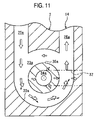
FIG. 11 is a horizontal, cross sectional view showing an internal space of FIG. 8 as simplified; and
FIG. 12 is a vertical, cross sectional view showing an internal space of FIG. 8 as simplified.
DETAILED DESCRIPTION OF THE PREFERRED EMBODIMENTS
FIGS. 1 and 2, respectively, are views showing a flow velocity measuring device 1, according to an embodiment of the invention, as viewed from obliquely upwardly of the front and obliquely downwardly of the back. The flow velocity measuring device 1 mainly serves to measure the flow velocity of an air, and comprises a housing 2 including a first layer substrate and a cover 3. The housing 2 is shaped to provide overhangs 4 on sides of a rectangular solid, the overhangs having screw holes 4 a for fixation of the flow velocity measuring device 1 to a location of measurement, the housing including an intake port 5 on a front surface thereof for taking in a flow of an air being measured, a first discharge port 6 and a second discharge port 7 on a back surface thereof, a first connector hole 8 a on a side thereof, and a second connector hole 8 b and a positioning hole 9 on a bottom surface thereof. The cover 3 is mounted on an upper surface of the housing 2 by means of two hooks 10 for engagement with the back surface of the flow velocity measuring device 1 and provided with two trimmer holes 11. A first connector 12 a and a second connector 12 b, respectively, are provided in the first connector hole 8 a and the second connector hole 8 b to be connected in parallel, and only one of the first connector 12 a and the second connector 12 b is used to be able to connect the flow velocity measuring device 1 to an external equipment. Trimmers 13 provided in the two trimmer holes 11, respectively, serve to adjust sensitivity of the flow velocity measuring device 1.
Further, as shown in FIG. 3, the flow velocity measuring device 1 accommodates an intermediate plate 14, a packing 15, and a circuit substrate 16, which makes a second layer substrate, in the housing 2 to secure them with the cover 3.
The housing 2 is provided on a side wall on the front with two elongate engagement holes 17, and on a side wall on the back with two engagement grooves 18, with which the hooks 10 engage. A recess 20 having the same thickness as that of the intermediate plate 14 is provided on a part of that inner wall of the first layer substrate 19, which defines a bottom wall, and a first layer flow passage 21 is defined by a groove provided on a bottom of the recess 20. As shown in FIG. 4, the first layer flow passage 21 includes two internal spaces 23 a, 23 b being recesses surrounded by curved (circular in the embodiment) wall surfaces 22 a, 22 b, respectively. Further, an introduction passage 25 a connecting tangentially to an end of the wall surface 22 a is provided to provide communication between an intake chamber 24 extending straight from the intake port 5 and the internal space 23 a, and a discharge passage 26 a connecting tangentially to the other end of the wall surface 22 a extending along the wall surface 22 a from the introduction passage 25 a is communicated to a combined discharge passage 27, which is communicated to the first discharge port 6. Further, there are provided a blind introduction passage 25 b connecting tangentially to an end of the wall surface 22 b of the internal space 23 b and a discharge passage 26 b connecting tangentially to the other end of the wall surface 22 b and connecting at 90 degrees to the discharge passage 26 a to be communicated to the combined discharge passage 27. Further, there are provided a sensor chamber 28 formed by partially enlarging the recess 20 of the first layer substrate 19, a measurement discharge passage 29 extended from the second discharge port 7, and a sensor discharge passage 30 for connection of the sensor chamber 28 and the measurement discharge passage 29.
The intermediate plate 14 comprises a plate that engages with the recess 20 in the housing 2 to seal an upper portion of the first layer flow passage 21, and a second layer flow passage 31 is defined by grooves provided on an upper surface as shown in FIGS. 5 and 6, which shows an upper surface and a back surface. The second layer flow passage 31 comprises a first connection passage 32 and a second connection passage 33, and branch passages 34 a, 34 b extending through the intermediate plate 14 are provided at one ends of the first connection passage 32 and the second connection passage 33. The branch passages 34 a, 34 b include cylindrical portions 35 a, 35 b, openings of which project from the back surface of the intermediate plate 14, a communication hole 36 extending through the intermediate plate 14 is provided at the other end of the first connection passage 32, and the other end of the second connection passage 33 is opened to a side of the intermediate plate 14.
The packing 15 is made of thin rubber to seal the intermediate plate 14 and an upper portion of the sensor discharge passage 30 of the housing 2, and an upper portion of the sensor chamber 28 is provided in a sensor hole 37 to be opened.
The circuit substrate 16 comprises a printed board, which constitutes a measurement circuit with the trimmers 13 and other elements, and includes the connectors 12 a, 12 b. As shown in FIG. 7, a sensor element 38 for measurement of wind velocity with the use of a heating element is mounted to a back surface of the circuit substrate 16. The sensor element 38 extends through the sensor hole 37 of the packing 15 to be arranged inside the sensor chamber 28.
The cover 3 has engagement pawls 39 engaging with the engagement holes 17 of the housing 2 and has the hooks 10 engaging with the engagement grooves 18 so that the intermediate plate 14, the packing 15, and the circuit substrate 16 are fixed inside the housing 2 to attach closely to one another.
FIG. 8 is a plan view showing a state, in which the intermediate plate 14 is mounted in the recess 20 in the housing 2, and an explanation will be given to a configuration of flow passages in the flow velocity measuring device 1 in an assembled state. The cylindrical portions 35 a, 35 b on the intermediate plate 14 are positioned substantially centrally of the internal spaces 23 a, 23 b of the first layer flow passage 21, and the branch passages 34 a, 34 b, respectively, are connected to the internal spaces 23 a, 23 b from above. The internal space 23 a is communicated to the first connection passage 32 of the second layer flow passage 31 through the branch passage 34 a and further to the introduction passage 25 b through the communication hole 36. The internal space 23 b, to which the introduction passage 25 b is connected, is communicated to one end of the second connection passage 33 of the second layer flow passage 31 through the branch passage 34 b opened centrally of the internal space 23 b, and the other end of the second connection passage 33 is communicated to the sensor chamber 28. Also, as shown in FIG. 9, which shows a cross section A—A in FIG. 8, the branch passages 34 a, 34 b are provided at right angle relative to a direction, in which the wall surfaces 22 a, 22 b are curved, and the cylindrical portions 35 a, 35 b project into the internal spaces 23 a, 23 b from above so that the branch passages 34 a, 34 b are opened at substantially a half of a height of the first layer flow passage 21.
FIG. 10 shows a state, in which two flow velocity measuring devices 1 are mounted in a duct 40. The duct 40 takes in an air through a filter 41 as indicated by an arrow. The flow velocity measuring devices 1 are fixed by means of screws 42 with intake ports 5 facing upstream of an air flows. The flow velocity measuring device 1 mounted to a side wall of the duct 40 has a wiring cord 43 for connection to an external equipment connected to the connector 12 a, and the wiring cord 43 is wired in a manner to be trained on an inner wall of the duct 40. On the other hand, the flow velocity measuring device 1 mounted to a bottom wall of the duct 40 has a wiring cord 43, which extends through the bottom wall of the duct 40, connected to the connector 12 b.
An explanation will be given to an air flow when the flow velocity of an air is measured by the flow velocity measuring device 1. As shown in FIG. 10, an air flow in the flow velocity measuring device 1 with the intake port 5 facing toward the wind is indicated by arrows in FIG. 8. When the flow velocity of an air outside the flow velocity measuring device 1 is 0.5 m/sec, an air taken into the intake chamber 24 from the intake port 5 passes through the introduction passage 25 a, which is narrower than the intake port 5, to be accelerated to about 2 m/sec to blow into the internal space 23 a along the wall surface 22 a. The air having blown into the internal space 23 a goes along the wall surface 22 a and round an outer periphery of the internal space 23 a to pass through the combined discharge passage 27 from the discharge passage 26 a at the flow velocity of about 0.9 m/sec to be discharged outside the flow velocity measuring device 1 from the first discharge port 6. However, a part of the air having blown into the internal space 23 a is not discharged from the discharge passage 26 a but continues to go around within the internal space 23 a, and passes through the branch passage 34 a of the intermediate plate 14 at the flow velocity of about 0.4 m/sec to be conducted to the first connection passage 32. An air taken out from the branch passage 34 a passes through the first connection passage 32 and further through the communication hole 36 to blow into the internal space 23 b from the introduction passage 25 b at the flow velocity of about 0.6 m/sec. In the same manner as in the internal space 23 a, about 70% of the air having blown into the internal space 23 b passes through the discharge passage 26 b and the combined discharge passage 27 to be discharged from the first discharge port 6, and about 30% of the air passes through the branch passage 34 b to flow into the second connection passage 33. An air taken out from the branch passage 34 b is conducted to the sensor chamber 28, and the flow velocity of the air is measured by the sensor element 38. Since the flow velocity of an air in the sensor element 38 is determined by the flow velocity of an air taken in from the intake port 5, the flow velocity of an air outside the flow velocity measuring device 1 can be calculated. An air, the flow velocity of which has been measured by the sensor element 38 in the sensor chamber 28, is discharged outside from the second discharge port 7 through the sensor discharge passage 30 and the measurement discharge passage 29.
Actions on an air in the internal spaces 23 a, 23 b will be described with reference to FIGS. 11 and 12, in which the internal space 23 a is simplified and shown in horizontal cross section and vertical cross section. Here, the packing 15 is not shown because it is not necessarily an essential element. An air blowing into the internal space 23 a from the introduction passage 25 a flows in a manner indicated by blank arrows in the figures. The air flows along the wall surface 22 a from the introduction passage 25 a in a manner to describe an arc, and discharged mainly from the discharge passage 26 a but a part of the air goes around within the internal space 23 a. At this time, dust and dirt contained in the air will continue to go straight according to a law of inertia as indicated by single arrows in the figures. In the case where an air describes an arc as in the embodiment, the inertial force is understood to be a centrifugal force acting in a direction perpendicular to a wall surface. Therefore, dust and dirt in the air is deflected toward the wall surface 22 a, so that a clean air with less dust and dirt are obtained at the center part of the internal space 23 a. An air flowing near the wall surface 22 a and containing much dust and dirt is discharged from the discharge passage 26 a along the wall surface 22 a, and the clean air present at the center part of the internal space 23 a passes through the branch passages 34 to flow into the first connection passage 32. In the flow velocity measuring device 1, a branch ratio of an air quantity taken out from the branch passage 34 a to an air quantity blowing into the internal space 23 a from the introduction passage 25 a is about 0.3.
Likewise, also within the internal space 23 b, about 70% of an air having blown from the introduction passage 25 b is discharged from the discharge passage 26 b, and about 30% of the air is taken out from the branch passage 34 b. Here, a centrifugal force acting on dust and dirt in an air, which goes around within the internal spaces 23 a, 23 b, is proportional to the square of the velocity thereof and inversely proportional to a round radius. In the flow velocity measuring device 1 according to the embodiment, since an air blowing into the internal space 23 b amounts to only a part of an air blowing into the internal space 23 a, the internal space 23 b is made small to make a flow passage narrow to increase the flow velocity of an air and a flow passage is made small in radius, whereby a centrifugal force acting on dust and dirt contained in an air is prevented from being decreased. In this manner, a clean air, from which dust and dirt are removed, is taken out from the branch passage 34 b to be conducted to the sensor chamber 28 through the second connection passage 33, and the flow velocity of the air is measured by the sensor element 38.
In the flow velocity measuring device 1, both a branch ratio in the internal space 23 a and a branch ratio in the internal space 23 b are about 0.3, and when such branch ratios are large, flows in radial directions of the internal spaces 23 a, 23 b to be directed to the branch passages 34 a, 34 b, respectively, from the introduction passages 25 a, 25 b are generated and flows along the wall surfaces 22 a, 22 are decreased, so that dust and dirt cannot be removed favorably. Therefore, flows of an air along the wall surfaces 22 a, 22 are preferably increased by making the branch ratios equal to or less than 0.5. Also, when the branch ratios are made excessively small, the flow velocity of an air in the sensor chamber 28 becomes too slow, and thus that change in output of the sensor element 38, which is caused by a difference in flow velocity, is made small and a gain becomes small. Therefore, the flow velocity measuring device 1 according to the invention is optimized by making the branch ratios small in a range, in which accuracy in air velocity measured by the sensor element 38 can be ensured, on the basis of a range of measurement, and shapes and sizes of flow passages.
When the flow velocity measuring device 1 is mounted with the intake port 5 disposed at the bottom in order to measure the flow velocity of an air flowing just above from below, the discharge passage 26 a of the internal space 23 a faces obliquely upwardly of the branch passage 34 a, so that an air will flow out from the discharge passage 26 a above the branch passage 34 a. At this time, since gravitation acts on dust and dirt in the air a part of the dust and dirt separates in some cases from a flow along the wall surface 22 a to fall in the branch passage 34 a. According to the embodiment, however, since the discharge passage 26 b of the internal space 23 b connected in series so as to further branch an air, which has been branched in the internal space 23 a, and then conduct the air to the sensor element 38, is arranged at right angle to the discharge passage 26 a, the discharge passage 26 b is directed obliquely downwardly of the branch passage 34 b to be free from adverse influences as in the internal space 23 a. Also, since even when the flow velocity measuring device 1 is mounted in any other direction, at least one of the internal space 23 a and the internal space 23 b can effectively discharge dust and dirt from the discharge passages 26 a, 26 b without being influenced by gravitation, a clean air is supplied to the sensor chamber 28 to eliminate degradation in accuracy due to adhesion and accumulation of dust and dirt on the sensor element 38. Further, when the internal spaces 23 a, 23 b are arranged in parallel, the trimmers 13 are used to adjust sensitivity to enable the flow velocity to be again measured with the use of the remaining flow passage even if large dust and heavy dirt should plug the flow passages.
Since the wall surfaces 22 a, 22 b are cylindrical-shaped, the inertial forces of an air and dust and dirt contained in the air are directed at right angle to the flow and in opposition to the wall surfaces 22 a, 22 b at all times, so that it is possible to efficiently curve the air flow without loss of the flow velocity to enable separation of dust and dirt in the air.
Also, since the openings of the branch passages 34 a, 34 b are defined in the cylindrical portions 35 a, 35 b projecting into the internal spaces 23 a, 23 b as shown in FIG. 7, an air blown from the introduction passages 25 a, 25 b can be guided from inside in a manner to flow along the wall surfaces 22 a, 22 b. Further, even when the flow velocity measuring device 1 is mounted to be turned upside down, and the branch passages 34 a, 34 b are extended downward from the internal spaces 23 a, 23 b, dust and dirt attracted by gravitation, in particular, heavy dust and dirt creepingly moving below the flow passage are blocked by the cylindrical portions 35 a, 35 b and so hard to enter the branch passages 34 a, 34 b. Also, in this case, there is a possibility that dust and dirt in upper portions of the cylindrical portions 35 a, 35 b fall in the branch passages due to gravitation. However, by arranging the internal spaces 23 a, 23 b, which are connected in parallel, at an angle of twist so as not to make the branch passages 34 a, 34 b in parallel to each other, the two internal spaces 23 a, 23 b are not mounted with the branch passages 34 a, 34 b disposed at the bottom at a time even when the flow velocity measuring device 1 is mounted in any direction, and either of them can effectively discharge dust and dirt without being adversely influenced by gravitation.
By laminating the housing 2, the intermediate plate 14, and the circuit substrate 16 to construct two planar flow passages composed of the first layer flow passage 21 and the second layer flow passage 31, and forming through-holes in the intermediate plate 14 to provide the branch passages 34 a, 34 b connected perpendicularly to the first layer flow passage 21 and the second layer flow passage 31, the flow velocity measuring device 1 is constructed to enable configuring a three-dimensional flow-passage even with an ordinary resin molding and readily realizing a construction including complicated flow passages having the effect described above. Since the sensor chamber 28, the sensor discharge passage 30, and the measurement discharge passage 29 do not need a two-layered structure of flow passages, they are independent from the first layer flow passage 21 and the second layer flow passage 31 in the embodiment (they are also considered to be flow passages across both the first layer flow passage 21 and the second layer flow passage 31), but they may be provided in the second layer flow passage on the intermediate plate 14, or may be provided in the first layer flow passage by forming a further through-hole in the intermediate plate 14 of the second connection passage 33. Further, the flow velocity measuring device 1 can be manufactured further inexpensively since it is constructed such that the housing 2 accommodating therein elements for formation of flow passages and the circuit substrate 16 mounting thereon the sensor element 38 essential for measurement of flow velocity can be used as elements to constitute flow passages.
The invention can be widely used to measure the flow velocity of a fluid containing therein dust and dirt, such as detection of plugging of a filter, air-volume control of an air conditioning equipment.

Claims (18)

1. A flow velocity measuring device comprising a flow passage comprising:
an internal space having a curved wall surface,
an introduction passage connected to the internal space at one end of the wall surface tangentially to the wall surface,
a discharge passage connected to the internal space at the other end of the wall surface tangentially to the wall surface, and
a branch passage connected to the internal space at substantially right angle to a direction, in which the wall surface is curved, and
a sensor element arranged in the branch passage or a flow passage connected to the branch passage, and
wherein a fluid is introduced into the internal space from the introduction passage to branch into the discharge passage and the branch passage, and
the flow velocity of the fluid taken out from the branch passage is measured by the sensor element, wherein
at least two internal spaces are provided to be connected in series so that the fluid taken out from the branch passage connected to one of the internal spaces is conducted to the introduction passage connected to the other of the internal spaces.
2. The flow velocity measuring device according to claim 1, wherein the internal spaces are arranged in different directions so that a direction, in which one of the branch passages is connected to the internal space, and a direction, in which the other of the branch passages is connected to the internal space, and/or a direction, in which one of the discharge passages is connected to the internal space, and a direction, in which the other of the discharge passages is connected to the internal space, are different from each other.
3. The flow velocity measuring device according to claim 1, wherein a direction, in which one of the branch passages is connected to the internal space, and a direction, in which the other of the branch passages is connected to the internal space, and/or a direction, in which one of the discharge passages is connected to the internal space, and a direction, in which the other of the discharge passages is connected to the internal space, are different by 90 degrees or more from each other.
4. The flow velocity measuring device according to claim 1, wherein the internal space is cylindrical in shape.
5. The flow velocity measuring device according to claim 1, wherein the branch passage comprises a cylinder projecting into the internal space.
6. A flow velocity measuring device comprising a flow passage comprising:
an internal space having a curved wall surface,
an introduction passage connected to the internal space at one end of the wall surface tangentially to the wall surface,
a discharge passage connected to the internal space at the other end of the wall surface tangentially to the wall surface, and
a branch passage connected to the internal space at substantially right angle to a direction, in which the wall surface is curved, and
a sensor element arranged in the branch passage or a flow passage connected to the branch passage, and
wherein a fluid is introduced into the internal space from the introduction passage to branch into the discharge passage and the branch passage, and
the flow velocity of the fluid taken out from the branch passage is measured by the sensor element, wherein
at least two internal spaces are provided, and the branch passage connected to one of the internal spaces and the introduction passage connected to the other of the internal space are communicated to each other.
7. The flow velocity measuring device according to claim 6, wherein the internal spaces are arranged in different directions so that a direction, in which one of the branch passages is connected to the internal space, and a direction, in which the other of the branch passages is connected to the internal space, and/or a direction, in which one of the discharge passages is connected to the internal space, and a direction, in which the other of the discharge passages is connected to the internal space, are different from each other.
8. The flow velocity measuring device according to claim 6, wherein a direction, in which one of the branch passages is connected to the internal space, and a direction, in which the other of the branch passages is connected to the internal space, and/or a direction, in which one of the discharge passages is connected to the internal space, and a direction, in which the other of the discharge passages is connected to the internal space, are different by 90 degrees or more from each other.
9. A flow velocity measuring device comprising a first layer substrate, a second layer substrate, and an intermediate plate interposed between the first layer substrate and the second layer substrate,
a first layer flow passage provided between the first layer substrate and the intermediate plate and including an internal space having a curved wall surface, an introduction passage connected to the internal space at one end of the wall surface tangentially to the wall surface, and a discharge passage connected to the internal space at the other end of the wall surface tangentially to the wall surface,
a branch passage provided on the intermediate plate to extend through the intermediate plate to be connected to the internal space,
a second layer flow passage provided between the intermediate plate and the second layer substrate to be connected to the branch passage,
a sensor element provided on the first layer substrate or the second layer substrate to be arranged in the second layer flow passage or a flow passage connected to the second layer flow passage, and
wherein a fluid is introduced into the internal space from the introduction passage to branch into the discharge passage and the branch passage, and
the flow velocity of the fluid taken into the second layer flow passage from the branch passage is measured by the sensor element.
10. The flow velocity measuring device according to claim 9, wherein
the second layer flow passage comprises a groove provided on the intermediate plate, and
the second layer substrate comprises a circuit substrate provided with the sensor element and a circuit, which processes a signal input into or output to the sensor element.
11. The flow velocity measuring device according to claim 10, wherein the first layer substrate defines a part of a housing to accommodate therein the intermediate plate and the second layer substrate.
12. The flow velocity measuring device according to claim 9, wherein the first layer substrate defines a part of a housing to accommodate therein the intermediate plate and the second layer substrate.
13. The flow velocity measuring device according to claim 9, wherein
the first layer flow passage includes at least two internal spaces,
the intermediate plate is provided with a communication hole, which extends through the intermediate plate from the introduction passage connected to one of the internal spaces, and
the second layer flow passage is arranged to provide communication between the branch passage connected to the other of the internal spaces and the communication hole.
14. The flow velocity measuring device according to claim 13, wherein directions of the discharge passages connected to the internal spaces are different by 90 degrees or more.
15. The flow velocity measuring device according to claim 9, wherein
the first layer flow passage includes at least two internal spaces, and
the second layer flow passage is arranged to provide communication between the branch passage connected to one of the internal spaces and the branch passage connected to the other of the internal spaces.
16. The flow velocity measuring device according to claim 15, wherein directions of the discharge passages connected to the internal spaces are different by 90 degrees or more.
17. The flow velocity measuring device according to claim 9, wherein the internal space is cylindrical-shaped.
18. The flow velocity measuring device according to claim 9, wherein the branch passage comprises a cylinder projecting into the internal space.
US11/067,149 2004-02-27 2005-02-25 Flow velocity measuring device Expired - Lifetime US7062963B2 (en)

Applications Claiming Priority (2)

Application Number Priority Date Filing Date Title
JP2004054475A JP4534526B2 (en) 2004-02-27 2004-02-27 Flow velocity measuring device
JPJP2004-054475 2004-02-27

Publications (2)

Publication Number Publication Date
US20050188760A1 US20050188760A1 (en) 2005-09-01
US7062963B2 true US7062963B2 (en) 2006-06-20

Family

ID=34747563

Family Applications (1)

Application Number Title Priority Date Filing Date
US11/067,149 Expired - Lifetime US7062963B2 (en) 2004-02-27 2005-02-25 Flow velocity measuring device

Country Status (5)

Country Link
US (1) US7062963B2 (en)
EP (1) EP1568999B1 (en)
JP (1) JP4534526B2 (en)
KR (1) KR100581137B1 (en)
CN (1) CN100381824C (en)

Cited By (3)

* Cited by examiner, † Cited by third party
Publication number Priority date Publication date Assignee Title
US20100051243A1 (en) * 2008-08-29 2010-03-04 Apple Inc. Methods and apparatus for cooling electronic devices using flow sensors
US20100135239A1 (en) * 2003-08-26 2010-06-03 Tuija Hurtta Method and system for establishing a connection between network elements
USD986825S1 (en) * 2019-11-14 2023-05-23 Lam Research Corporation Connector backshell

Families Citing this family (14)

* Cited by examiner, † Cited by third party
Publication number Priority date Publication date Assignee Title
JP4120637B2 (en) * 2004-11-30 2008-07-16 オムロン株式会社 Flow velocity measuring device
JP3832498B1 (en) * 2005-06-24 2006-10-11 オムロン株式会社 Flow measuring device
US20070171086A1 (en) * 2005-10-26 2007-07-26 Belady Christian L Environmental monitor
DE102007035187A1 (en) 2007-07-27 2009-01-29 Continental Automotive Gmbh Air flow sensor
JP5003372B2 (en) * 2007-09-13 2012-08-15 オムロン株式会社 Flow measuring device
WO2009057752A1 (en) * 2007-10-31 2009-05-07 The Foundation For The Promotion Of Industrial Science Molding material flow speed measuring method and flow speed measuring device
JP5061963B2 (en) * 2008-03-05 2012-10-31 オムロン株式会社 Flow sensor
JP5817598B2 (en) * 2012-03-07 2015-11-18 オムロン株式会社 Fluid measuring device
US10641630B2 (en) 2015-09-30 2020-05-05 Hitachi Automotive Systems, Ltd. Physical quantity detection device
US10655989B2 (en) 2017-09-12 2020-05-19 Silicon Microstructures, Inc. Pressure sensor cap having flow path with dimension variation
DE102017131204A1 (en) 2017-12-22 2019-06-27 Tdk Electronics Ag Sensor component and mobile communication device including the same
JP6686126B2 (en) * 2018-12-28 2020-04-22 日立オートモティブシステムズ株式会社 Thermal flow meter
CN109596184A (en) * 2018-12-29 2019-04-09 连云港连利·福思特表业有限公司 A kind of hybrid water meter
US11268839B2 (en) 2019-03-05 2022-03-08 Measurement Specialties, Inc. Resistive flow sensor

Citations (3)

* Cited by examiner, † Cited by third party
Publication number Priority date Publication date Assignee Title
JPH11166720A (en) 1997-12-04 1999-06-22 Gastar Corp Dust trap assembly
US6647776B2 (en) * 2001-05-08 2003-11-18 Ngk Spark Plug Co., Ltd. Split-flow flowmeter with a profusion facing the detection element
US6868122B2 (en) * 2001-02-07 2005-03-15 Sun Microsystems, Inc. Distributed intraframe transmission in digital video compression

Family Cites Families (12)

* Cited by examiner, † Cited by third party
Publication number Priority date Publication date Assignee Title
US4914947A (en) * 1988-09-30 1990-04-10 Honeywell Inc. Sampling probe flow sensor
JP2602117B2 (en) * 1990-04-23 1997-04-23 山武ハネウエル株式会社 Flow sensor
JPH05223835A (en) * 1992-02-07 1993-09-03 Yamatake Honeywell Co Ltd Flow velocity detector
JPH0670635B2 (en) * 1992-10-16 1994-09-07 寿 今井 Velocity measurement duct
CN2198597Y (en) * 1994-03-18 1995-05-24 贺瑞英 Automatic sewage-discharging gas meter
JPH1183886A (en) 1997-09-11 1999-03-26 Zexel Corp Capacitance type microflow sensor, its manufacture, and fixture for externally attaching the same
DE19815654A1 (en) * 1998-04-08 1999-10-14 Bosch Gmbh Robert Measuring device for measuring the mass of a medium flowing in a line
JPH11304832A (en) 1998-04-24 1999-11-05 Aichi Tokei Denki Co Ltd Electromagnetic current meter
KR20010039993A (en) * 1999-10-06 2001-05-15 오카무라 가네오 Flow Rate and Flow Velocity Measurement Device
DE10019149B4 (en) * 2000-04-18 2007-06-06 Robert Bosch Gmbh Device for determining at least one parameter of a flowing medium
JP3716163B2 (en) * 2000-06-16 2005-11-16 株式会社日立製作所 Air flow measurement device
DE10135142A1 (en) * 2001-04-20 2002-10-31 Bosch Gmbh Robert Device for determining at least one parameter of a medium flowing in a line

Patent Citations (3)

* Cited by examiner, † Cited by third party
Publication number Priority date Publication date Assignee Title
JPH11166720A (en) 1997-12-04 1999-06-22 Gastar Corp Dust trap assembly
US6868122B2 (en) * 2001-02-07 2005-03-15 Sun Microsystems, Inc. Distributed intraframe transmission in digital video compression
US6647776B2 (en) * 2001-05-08 2003-11-18 Ngk Spark Plug Co., Ltd. Split-flow flowmeter with a profusion facing the detection element

Non-Patent Citations (1)

* Cited by examiner, † Cited by third party
Title
Patent Abstracts of Japan, Publication No. 11-166720 dated Jun. 22, 1999, one page.

Cited By (5)

* Cited by examiner, † Cited by third party
Publication number Priority date Publication date Assignee Title
US20100135239A1 (en) * 2003-08-26 2010-06-03 Tuija Hurtta Method and system for establishing a connection between network elements
US20100051243A1 (en) * 2008-08-29 2010-03-04 Apple Inc. Methods and apparatus for cooling electronic devices using flow sensors
US8695690B2 (en) * 2008-08-29 2014-04-15 Apple Inc. Methods for cooling electronic devices using flow sensors
US9904334B2 (en) 2008-08-29 2018-02-27 Apple Inc. Cooling electronic devices using flow sensors
USD986825S1 (en) * 2019-11-14 2023-05-23 Lam Research Corporation Connector backshell

Also Published As

Publication number Publication date
CN100381824C (en) 2008-04-16
JP4534526B2 (en) 2010-09-01
CN1661374A (en) 2005-08-31
US20050188760A1 (en) 2005-09-01
JP2005241569A (en) 2005-09-08
EP1568999A3 (en) 2007-04-25
EP1568999A2 (en) 2005-08-31
KR100581137B1 (en) 2006-05-16
EP1568999B1 (en) 2018-01-17

Similar Documents

Publication Publication Date Title
US7062963B2 (en) Flow velocity measuring device
JP5279667B2 (en) Thermal air flow sensor
JP4120637B2 (en) Flow velocity measuring device
EP1232487B1 (en) Smoke detector with sensor having improved mounting configuration
US10663180B2 (en) Indoor unit for air-conditioning apparatus
EP2306162B1 (en) Flow-rate measurement apparatus
AU2006263279B2 (en) Flow rate measurement device
CN116337724B (en) Detection device and electronic equipment
JP6981560B2 (en) Substance detection system
CN214373115U (en) Sensor test fixture
JP2009520175A (en) Fan intake sensor
CN215372870U (en) Wire controller
JP7529528B2 (en) Electronics
CN218959123U (en) MEMS sensor, MEMS microphone and electronic cigarette
JP7518465B2 (en) Packaged Flow Sensor
JP5003372B2 (en) Flow measuring device
WO2019198720A1 (en) Sensor unit
JP2002181754A (en) Moisture sensor and production method thereof
JP6569617B2 (en) OBE
JP2025524706A (en) Sensor module for modular connector
KR101713865B1 (en) Thermal flowmeter
US20170290185A1 (en) Housing structure of electronic device
JPH08215399A (en) Pachinko ball detector and pachinko ball counter
JPH0810389A (en) Pachinko ball detecting device, and pachinko ball counting device

Legal Events

Date Code Title Description
AS Assignment

Owner name: OMRON CORPORATION, JAPAN

Free format text: ASSIGNMENT OF ASSIGNORS INTEREST;ASSIGNORS:FUJIWARA, TOSHIMITSU;NOZOE, SATOSHI;UEDA, NAOTSUGU;REEL/FRAME:016331/0850

Effective date: 20050208

FEPP Fee payment procedure

Free format text: PAYOR NUMBER ASSIGNED (ORIGINAL EVENT CODE: ASPN); ENTITY STATUS OF PATENT OWNER: LARGE ENTITY

STCF Information on status: patent grant

Free format text: PATENTED CASE

FPAY Fee payment

Year of fee payment: 4

FPAY Fee payment

Year of fee payment: 8

MAFP Maintenance fee payment

Free format text: PAYMENT OF MAINTENANCE FEE, 12TH YEAR, LARGE ENTITY (ORIGINAL EVENT CODE: M1553)

Year of fee payment: 12