US7056263B2 - Electronic clutch-to-clutch transmission control system - Google Patents
Electronic clutch-to-clutch transmission control system Download PDFInfo
- Publication number
- US7056263B2 US7056263B2 US10/317,554 US31755402A US7056263B2 US 7056263 B2 US7056263 B2 US 7056263B2 US 31755402 A US31755402 A US 31755402A US 7056263 B2 US7056263 B2 US 7056263B2
- Authority
- US
- United States
- Prior art keywords
- torque
- coming
- clutch
- going
- determining
- Prior art date
- Legal status (The legal status is an assumption and is not a legal conclusion. Google has not performed a legal analysis and makes no representation as to the accuracy of the status listed.)
- Expired - Fee Related, expires
Links
Images


Classifications
-
- F—MECHANICAL ENGINEERING; LIGHTING; HEATING; WEAPONS; BLASTING
- F16—ENGINEERING ELEMENTS AND UNITS; GENERAL MEASURES FOR PRODUCING AND MAINTAINING EFFECTIVE FUNCTIONING OF MACHINES OR INSTALLATIONS; THERMAL INSULATION IN GENERAL
- F16H—GEARING
- F16H61/00—Control functions within control units of change-speed- or reversing-gearings for conveying rotary motion ; Control of exclusively fluid gearing, friction gearing, gearings with endless flexible members or other particular types of gearing
- F16H61/04—Smoothing ratio shift
- F16H61/06—Smoothing ratio shift by controlling rate of change of fluid pressure
- F16H61/061—Smoothing ratio shift by controlling rate of change of fluid pressure using electric control means
Definitions
- the present invention relates to transmission systems, and more particularly to a transmission system with improved clutch-to-clutch shift control.
- Automatic transmissions include a plurality of gears and associated components that are manipulated to drive an output shaft using different gear ratios.
- a transmission controller monitors vehicle operating conditions and driver input to determine whether an up-shift or a down-shift should occur. During a shift, an on-coming component gradually engages the next gear as an off-going component gradually disengages the present gear.
- a one-way clutch or diode is implemented as an off-going component to transfer torque through the powertrain.
- the release of the off-going component is controlled based upon the rate of the on-coming component during the shift.
- Conventional transmission systems use compliance devices, such as accumulators, wave plates, and orifices, and hydraulic line pressure to control shift feel.
- this configuration is overly complex, increases cost, and requires a large packaging envelope within the transmission.
- a transmission system includes a first clutch, a second clutch, and a controller.
- the controller communicates with the first and second clutches and commands a gear shift.
- the controller calculates a torque phase time for the gear shift and determines a desired torque trajectory within said torque phase time.
- the controller determines on-coming torque values for the second clutch and off-going torque values for the first clutch to achieve the desired torque trajectory within the torque phase time.
- the first clutch selectively interconnects an input shaft to an output shaft through a first gear.
- the second clutch selectively interconnects the input shaft to the output shaft through a second gear.
- the first and second gears respectively provide first and second gear ratios.
- the controller calculates a desired torque of an output shaft.
- the desired torque trajectory is based on the desired torque.
- the controller calculates an on-coming clutch pressure based on the on-coming torque value, and an off-going clutch pressure based on the off-going torque value.
- the controller delays actuation of the first and second clutches to compensate for hydraulic delays.
- the on-coming and off-going torque values are based on an input torque, a rotational speed of a torque converter turbine, and an output torque of an output shaft.
- FIG. 1 is a functional block diagram of an exemplary vehicle transmission system according to the present invention
- FIG. 2 is a graph depicting parameter values during an up-shift of an automatic transmission according to the present invention.
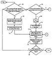
- FIGS. 3A and 3B illustrate a flowchart detailing a transmission shift control method of the present invention.
- an exemplary automatic transmission 10 includes a torque converter 12 , a plurality of gear sets 14 a , 14 b , hydraulically-actuated multiple clutches 16 a , 16 b , a transmission control system 18 , and a hydraulic pump 20 .
- the hydraulic pump 20 may be driven by the engine or an electric motor.
- the torque converter 12 enables start-off, provides torque multiplication, and absorbs harmonic vibrations within the vehicle drivetrain.
- the gear sets 14 a , 14 b are located between an input shaft 22 , which is connected to the torque converter 12 , and an output shaft 24 .
- the gear sets 14 a , 14 b enable the output shaft 24 to be driven at multiple gear ratios.
- the transmission control system 18 selectively engages the multiple clutches 16 a , 16 b .
- the hydraulic pump 20 supplies hydraulic fluid pressure for valve body and shift components and/or for the torque converter 12 .
- the transmission control system 18 defines gear selection and shift points and regulates demand-response shifting. Demand-response shifting is based on a shift program that is selected by the driver using a selector 26 , a position of an accelerator 28 , engine operating conditions, and/or vehicle speed.
- the transmission control system 18 is generally a combined hydraulic and electric system.
- the transmission control system 18 hydraulically actuates the clutches 16 a , 16 b .
- the transmission control system 18 actuates gear selection and modulates the clutch pressure electronically in accordance with the torque flowing through the transmission 10 .
- the transmission control system 18 includes a controller 30 that communicates with a plurality of sensors.
- a speed sensor 32 monitors engine speed and a position sensor 33 monitors selector-lever position.
- Load sensors 35 and speed sensor 37 monitor the torque converter load and the rotational speed of the output shaft 24 , respectively.
- the controller 30 adjusts analog or digital pressure regulators 36 to control clutch pressure.
- Shift-quality depends upon the accuracy that the pressure of the clutches 16 a , 16 b is adjusted to the level of torque transmitted.
- the level of torque transmitted is estimated based on engine load and output shaft speed.
- one clutch gradually disengages (i.e., is off-going) as another clutch gradually engages (i.e., is on-coming).
- Shifting between gear ratios occurs in two distinct phases: a torque phase and an inertia phase.
- torque phase the speed of the input shaft 22 from the torque converter 12 remains constant.
- inertia phase there is a response to the shift and the input shaft 22 changes speed.
- For an up-shift the speed is decreased.
- For a down-shift the speed is increased.
- a first gear 40 of the first gear set 14 a is initially coupled to the input shaft 22 to drive the output shaft 24 at a first gear ratio.
- the clutch 16 a gradually decreases engagement of the first gear 40 with the input shaft 22 (i.e., is off-going).
- the second clutch 16 b gradually increases engagement of a second gear 42 of the second gear set 14 b with the input shaft 22 (i.e., is on-coming).
- the first clutch 16 a completely disengages the first gear 40 from the input shaft 22 and the second clutch 16 b couples the second gear 42 with the input shaft 22 to drive the output shaft 24 at a second gear ratio.
- the present invention provides a transmission shift control method that calculates the required clutch pressure commands during the torque phase of an up-shift.
- the transmission shift control method avoids flare and overlap and improves shift quality.
- T off aT o +bT i +c ⁇ t
- T on dT o +eT i +f ⁇ t
- T o is the output torque of the transmission output shaft 24 .
- T i is the torque from the torque converter and ⁇ t is the input shaft acceleration.
- the values a, b, c, d, e, and f are theoretical constants for each shift type (i.e., on or off). Exemplary values for these constants are provided in Table 1 below for an exemplary six-speed automatic transmission.
- the transmission control system 18 determines a desired torque phase time based on a driver's input. For example, if the driver fully depresses the accelerator 28 , the desired torque phase time will reflect a wide-open throttle (WOT) condition. The determination of the desired torque phase time also depends upon pre-programmed calibration parameters. Using the desired torque phase time, a desired output torque trajectory is calculated. On-coming and off-going torque commands are calculated based on the desired output torque trajectory. The on-coming and off-going torque commands are delayed for hydraulic delays in the transmission 10 to provide a seamless clutch torque exchange prior to a speed change.
- WOT wide-open throttle
- the up-shift torque phase includes four states: initialization, updating, trimming to inertia phase, and completion.
- the up-shift control determines the torque phase state and the torque phase pressure commands.
- the up-shift control determines whether the on-coming shift has been signaled or whether a torque phase delay is present, and whether the torque phase state is at initialization in step 100 . If true, the up-shift control continues with step 102 and calculates the desired shift parameters. Otherwise, the up-shift control continues with step 104 . In step 104 , the up-shift control determines whether either the on-coming shift or the torque phase state are complete. If either is complete, the up-shift control continues with step 106 . Otherwise, the control continues with step 108 .
- step 108 the up-shift control determines whether a torque phase trim initialization time has been reached or whether the torque phase state is at trim.
- the trim state is indicative of the transition between the torque and the inertia phases.
- the trim initialization time is determined as a percent of the torque phase time. For example, if the torque phase time is 300 ms, a pre-programmed calibration value sets the trim initialization time to 75% or 225 ms. Once the torque phase achieves the 225 ms point, trimming is initialized. If the torque phase trim initialization time has been reached or the torque phase state is at trim, the up-shift continues with step 110 to trim the torque phase. Otherwise, the up-shift control continues with step 112 . In step 112 , the up-shift control updates the desired output torque trajectory for changes occurring during the torque phase of the up-shift.
- step 102 the up-shift control calculates the initial output torque and the desired output torque trajectory time ( ⁇ t o ) (see FIG. 2 ) based on the present gear ratio and input torque.
- step 114 the up-shift control calculates the off-going and on-coming torques of the active clutches using the equations described above. Once the off-going and on-coming torques have been calculated, a respective delay to the ultimate output to the solenoid drivers is initiated to compensate for hydraulic delays in step 116 .
- step 118 the pressures applied to actuate the off-going and on-coming clutches are determined. After determining the pressures in step 118 , the controller determines whether the torque phase has ended and the inertia phase has started. If the torque phase has ended, up-shift control ends. If the torque phase has not ended, up-shift control loops back to step 100 .
- step 104 the up-shift control determines whether either the on-coming stage or the torque phase state of the up-shift is complete. In other words, the controller determines whether the up-shift has been completed so that the on-coming clutch can be fully engaged and the off-going clutch can be fully disengaged.
- step 106 control commands T off to zero and T on to maximum.
- step 120 the up-shift control flags the torque phase state as being complete if not flagged previously. The up-shift control continues with steps 116 , 118 and 119 .
- step 108 the up-shift control determines whether either a torque phase trim initialization time has been reached or the torque phase state is at trim.
- step 110 a time interpolation of the on-coming torque phase clutch torque to the inertia phase clutch torque.
- the on-coming torque phase clutch torque is ramped to achieve the commanded inertia phase clutch torque over the trimming period. The equations are then used to back-calculate equivalent output torque and off-going clutch torque to smoothly transition into the inertia phase.
- step 122 the torque phase state is set to trim.
- step 124 the up-shift control determines whether a torque phase trim time has expired or whether the torque phase clutch torque is equivalent to an inertia phase clutch torque.
- step 126 the up-shift control continues with step 126 and declares the torque phase state complete. If neither is true, the up-shift control continues with steps 116 , 118 and 119 . Once the torque phase state is declared complete in step 126 , the up-shift control continues with steps 116 , 118 and 119 .
- the desired output torque trajectory is updated for input torque changes resulting from a driver's intent. For example, during the torque phase, a driver may either increase or decrease pressure on the accelerator pedal to alter the input torque.
- the torque phase state is set to model ramp. In this state, the controller 30 continuously calculates the on-coming and off-going torques to achieve the desired torque trajectory.
- the on-coming and off-going torques are calculated based on the present operating conditions according to the equations provided above.
- the up-shift control determines whether a pre-programmed on-coming inertia phase torque is less than or equal to the calculated torque phase on-coming torque. In this manner, completion of the torque phase is determined.
- step 134 If the on-coming inertia phase torque is less than or equal to the calculated torque phase on-coming torque then the up-shift control continues with step 134 and declares the torque phase state complete. Otherwise the up-shift control continues with steps 116 , 118 and 119 described in detail above.
- the up-shift control of the present invention enables calibration of torque phase times and system control to dynamically determine the on-coming and off-going clutch pressures. As a result, a desired torque trajectory or profile can be readily achieved and system calibration effort is reduced. Further, the up-shift control allows adaptive learning to improve shift quality over time. Overall, the up-shift control enables improved shift quality and feel while minimizing hardware complexity and size.
Landscapes
- Engineering & Computer Science (AREA)
- General Engineering & Computer Science (AREA)
- Physics & Mathematics (AREA)
- Fluid Mechanics (AREA)
- Mechanical Engineering (AREA)
- Control Of Transmission Device (AREA)
- Gear-Shifting Mechanisms (AREA)
Abstract
Description
T off =aT o +bT i +cη t
T on =dT o +eT i +fη t
The equations determine the clutch torques that are necessary to achieve a desired output torque trajectory for a given input torque and torque converter turbine acceleration. In the equations, To is the output torque of the
| TABLE 1 | |
| Calibration | Up- |
| Value |
| 1st to 2nd | 2nd to 3rd | 3rd to 4th | 4th to 5th | 5th to 6th | |
| a | 1.42 | −1.00 | −1.46 | 1.50 | −2.2979 |
| b | −1.6359 | 1.5319 | 1.2441 | −3.5464 | 1.5319 |
| c | 0.0156 | −0.01 | −0.0157 | 0.0196 | −0.0265 |
| d | −1.88 | −0.6479 | −1.42 | −0.5 | −1.7979 |
| e | 2.88 | 1.5319 | 1.6359 | 2.0145 | 1.5319 |
| f | −0.0233 | −0.0091 | −0.0193 | −0.0113 | −0.0228 |
As can be appreciated, the constants will vary depending upon the particular transmission type that is used.
Claims (22)
Priority Applications (3)
| Application Number | Priority Date | Filing Date | Title |
|---|---|---|---|
| US10/317,554 US7056263B2 (en) | 2002-12-12 | 2002-12-12 | Electronic clutch-to-clutch transmission control system |
| DE10357500A DE10357500B4 (en) | 2002-12-12 | 2003-12-09 | Electronic control system for the clutch change in a transmission |
| JP2003412721A JP2004190858A (en) | 2002-12-12 | 2003-12-11 | Electrical control system for inter-clutch transition |
Applications Claiming Priority (1)
| Application Number | Priority Date | Filing Date | Title |
|---|---|---|---|
| US10/317,554 US7056263B2 (en) | 2002-12-12 | 2002-12-12 | Electronic clutch-to-clutch transmission control system |
Publications (2)
| Publication Number | Publication Date |
|---|---|
| US20040116250A1 US20040116250A1 (en) | 2004-06-17 |
| US7056263B2 true US7056263B2 (en) | 2006-06-06 |
Family
ID=32506155
Family Applications (1)
| Application Number | Title | Priority Date | Filing Date |
|---|---|---|---|
| US10/317,554 Expired - Fee Related US7056263B2 (en) | 2002-12-12 | 2002-12-12 | Electronic clutch-to-clutch transmission control system |
Country Status (3)
| Country | Link |
|---|---|
| US (1) | US7056263B2 (en) |
| JP (1) | JP2004190858A (en) |
| DE (1) | DE10357500B4 (en) |
Cited By (8)
| Publication number | Priority date | Publication date | Assignee | Title |
|---|---|---|---|---|
| US20080059109A1 (en) * | 2006-08-29 | 2008-03-06 | James Rankin | Method and apparatus to measure force-travel profile of a shifter in a vehicle environment |
| US20080182715A1 (en) * | 2006-12-29 | 2008-07-31 | Mike Dickinson | Automotive-transmission clutch-pressure duration |
| US20090018735A1 (en) * | 2007-07-11 | 2009-01-15 | Gm Global Technology Operations, Inc. | Apparatus and method for decreasing an upshift delay in an automatic transmission |
| US20110231072A1 (en) * | 2010-03-18 | 2011-09-22 | Dr. Ing. H.C. F. Porsche Aktiengesellschaft | Method for controlling a drivetrain of a motor vehicle having an automatic clutch |
| DE102012211500A1 (en) | 2011-07-07 | 2013-03-07 | GM Global Technology Operations LLC (n.d. Ges. d. Staates Delaware) | System and method for improved double-transition gearshifts for automatic transmissions |
| DE102014102576A1 (en) | 2013-03-12 | 2014-09-18 | GM Global Technology Operations LLC (n. d. Gesetzen des Staates Delaware) | A system and method for performing a double-transition shift in a over-drive transmission having opposite clutch slip and torque transport directions |
| US10408342B2 (en) | 2016-10-28 | 2019-09-10 | Ford Global Technologies, Llc | Transmission control to avoid gain switch during shift |
| US10995852B2 (en) | 2019-06-04 | 2021-05-04 | Ford Global Technologies, Llc | Systems and methods for controlling friction elements |
Families Citing this family (5)
| Publication number | Priority date | Publication date | Assignee | Title |
|---|---|---|---|---|
| KR100828672B1 (en) * | 2003-12-05 | 2008-05-09 | 현대자동차주식회사 | Upshift Control Device and Method of Automatic Transmission |
| US8775044B2 (en) * | 2011-06-08 | 2014-07-08 | Ford Global Technologies, Llc | Clutch torque trajectory correction to provide torque hole filling during a ratio upshift |
| US10323702B2 (en) * | 2016-10-28 | 2019-06-18 | Ford Global Technologies, Llc | Adaption of off-going clutch torque |
| CN110116724A (en) * | 2018-02-05 | 2019-08-13 | 江苏兴云动力科技有限公司 | A method of improving hybrid power system clutch separation |
| CN115899237B (en) * | 2022-10-31 | 2024-06-14 | 重庆长安汽车股份有限公司 | Method for inhibiting clutch sliding friction abnormal sound of P2 configuration hybrid assembly in gear shifting and downshifting and electronic equipment |
Citations (7)
| Publication number | Priority date | Publication date | Assignee | Title |
|---|---|---|---|---|
| US5304102A (en) * | 1991-02-21 | 1994-04-19 | Nissan Motor Co., Ltd. | Control for shift in automatic transmission |
| US5368531A (en) * | 1991-12-03 | 1994-11-29 | Aisin Aw Co., Ltd. | Control method of and system thereof for inversely proportionally raising and lowering servo hydraulic pressure, based on input torque, for engaging and disengaging frictional elements in automatic transmission |
| US5779594A (en) * | 1992-09-16 | 1998-07-14 | Hitachi, Ltd. | Driving force control system for a vehicle |
| US6243637B1 (en) * | 1998-03-19 | 2001-06-05 | Hitachi, Ltd. | Control apparatus and method for automatic transmission by oil pressure on clutch |
| US20010016539A1 (en) * | 2000-02-22 | 2001-08-23 | Hiroyuki Yuasa | Apparatus and a method for controlling an automatic transmission |
| US6334833B1 (en) * | 1998-05-29 | 2002-01-01 | Hitachi, Ltd. | Control apparatus for automatic transmission and control method for automatic transmission |
| US6503165B1 (en) * | 1999-10-25 | 2003-01-07 | Aisin Aw Co., Ltd. | Hydraulic control device for automatic transmission |
Family Cites Families (1)
| Publication number | Priority date | Publication date | Assignee | Title |
|---|---|---|---|---|
| CA2327879C (en) * | 1999-12-09 | 2005-02-15 | Honda Giken Kogyo Kabushiki Kaisha | Control system for automatic vehicle transmissions |
-
2002
- 2002-12-12 US US10/317,554 patent/US7056263B2/en not_active Expired - Fee Related
-
2003
- 2003-12-09 DE DE10357500A patent/DE10357500B4/en not_active Expired - Fee Related
- 2003-12-11 JP JP2003412721A patent/JP2004190858A/en active Pending
Patent Citations (7)
| Publication number | Priority date | Publication date | Assignee | Title |
|---|---|---|---|---|
| US5304102A (en) * | 1991-02-21 | 1994-04-19 | Nissan Motor Co., Ltd. | Control for shift in automatic transmission |
| US5368531A (en) * | 1991-12-03 | 1994-11-29 | Aisin Aw Co., Ltd. | Control method of and system thereof for inversely proportionally raising and lowering servo hydraulic pressure, based on input torque, for engaging and disengaging frictional elements in automatic transmission |
| US5779594A (en) * | 1992-09-16 | 1998-07-14 | Hitachi, Ltd. | Driving force control system for a vehicle |
| US6243637B1 (en) * | 1998-03-19 | 2001-06-05 | Hitachi, Ltd. | Control apparatus and method for automatic transmission by oil pressure on clutch |
| US6334833B1 (en) * | 1998-05-29 | 2002-01-01 | Hitachi, Ltd. | Control apparatus for automatic transmission and control method for automatic transmission |
| US6503165B1 (en) * | 1999-10-25 | 2003-01-07 | Aisin Aw Co., Ltd. | Hydraulic control device for automatic transmission |
| US20010016539A1 (en) * | 2000-02-22 | 2001-08-23 | Hiroyuki Yuasa | Apparatus and a method for controlling an automatic transmission |
Cited By (14)
| Publication number | Priority date | Publication date | Assignee | Title |
|---|---|---|---|---|
| US20080059109A1 (en) * | 2006-08-29 | 2008-03-06 | James Rankin | Method and apparatus to measure force-travel profile of a shifter in a vehicle environment |
| US7536918B2 (en) * | 2006-08-29 | 2009-05-26 | Ford Motor Company | Method and apparatus to measure force-travel profile of a shifter in a vehicle environment |
| US20080182715A1 (en) * | 2006-12-29 | 2008-07-31 | Mike Dickinson | Automotive-transmission clutch-pressure duration |
| US20090018735A1 (en) * | 2007-07-11 | 2009-01-15 | Gm Global Technology Operations, Inc. | Apparatus and method for decreasing an upshift delay in an automatic transmission |
| US8214116B2 (en) | 2007-07-11 | 2012-07-03 | GM Global Technology Operations LLC | Apparatus and method for decreasing an upshift delay in an automatic transmission |
| US20110231072A1 (en) * | 2010-03-18 | 2011-09-22 | Dr. Ing. H.C. F. Porsche Aktiengesellschaft | Method for controlling a drivetrain of a motor vehicle having an automatic clutch |
| DE102012211500A1 (en) | 2011-07-07 | 2013-03-07 | GM Global Technology Operations LLC (n.d. Ges. d. Staates Delaware) | System and method for improved double-transition gearshifts for automatic transmissions |
| US8862352B2 (en) | 2011-07-07 | 2014-10-14 | GM Global Technology Operations LLC | System and method for improved double transition shift operations for automatic transmissions |
| DE102012211500B4 (en) | 2011-07-07 | 2022-02-10 | GM Global Technology Operations, LLC (n.d. Ges. d. Staates Delaware) | Method for improved dual transition shifts for automatic transmissions |
| DE102014102576A1 (en) | 2013-03-12 | 2014-09-18 | GM Global Technology Operations LLC (n. d. Gesetzen des Staates Delaware) | A system and method for performing a double-transition shift in a over-drive transmission having opposite clutch slip and torque transport directions |
| US8983745B2 (en) | 2013-03-12 | 2015-03-17 | GM Global Technology Operations LLC | System and method of executing a double transition shift in a transmission with transitioning clutch having opposite clutch slip and torque carrying directions |
| DE102014102576B4 (en) | 2013-03-12 | 2021-08-19 | GM Global Technology Operations LLC (n. d. Gesetzen des Staates Delaware) | A system and method for performing a double transition shift in a transmission having an override clutch having opposite clutch slip and torque transport directions |
| US10408342B2 (en) | 2016-10-28 | 2019-09-10 | Ford Global Technologies, Llc | Transmission control to avoid gain switch during shift |
| US10995852B2 (en) | 2019-06-04 | 2021-05-04 | Ford Global Technologies, Llc | Systems and methods for controlling friction elements |
Also Published As
| Publication number | Publication date |
|---|---|
| DE10357500B4 (en) | 2013-01-17 |
| DE10357500A1 (en) | 2004-07-15 |
| JP2004190858A (en) | 2004-07-08 |
| US20040116250A1 (en) | 2004-06-17 |
Similar Documents
| Publication | Publication Date | Title |
|---|---|---|
| US4653351A (en) | Clutch-to-clutch power-on downshifting in a motor vehicle automatic transmission | |
| US6656087B1 (en) | Multi-stage skip downshift control for an automatic transmission | |
| US5036729A (en) | Coast-sync-coast downshift control method for clutch-to-clutch transmission shifting | |
| CN100554736C (en) | Automatic transmission is opened the Method of Adaptive Control and the equipment of throttle kickdown | |
| US5046383A (en) | Acceleration-based control of power-on clutch-to-clutch upshifting in an automatic transmission | |
| US5113343A (en) | Sequenced control of double transition powered downshifting in an automatic transmission | |
| US7212898B2 (en) | Method and apparatus for adaptive control of power-on skip through neutral downshifts | |
| US5445576A (en) | Engine torque management during coast downshifting of an automatic shift transmission | |
| US7056263B2 (en) | Electronic clutch-to-clutch transmission control system | |
| US5038636A (en) | Double transition downshift control for an automatic transmission | |
| JPH0650145B2 (en) | Gear change control method in auto transmission | |
| JPH04262164A (en) | Multistage mode type pressure adaptive control device for automatic power transmitting device and method thereof | |
| JP2672063B2 (en) | Control device for automatic transmission | |
| US9482341B2 (en) | Control device for automatic transmission | |
| CN101797919B (en) | Control device for vehicle drive device and control method for vehicle drive device | |
| EP0800124B1 (en) | Fuzzy logic adaptive shift control | |
| JPH08105533A (en) | Power shift transmission control method | |
| JP4192095B2 (en) | Shift control device for automatic transmission | |
| US7912617B2 (en) | Air purge method for a rotating clutch | |
| KR101826547B1 (en) | Apparatus for controlling for automatic transmission and method thereof | |
| US6334082B1 (en) | Shift control method for automatic transmission | |
| US8255129B2 (en) | Multi-stage non-sequential downshift control for an automatic transmission | |
| US7632215B2 (en) | Transmission downshift swap-shift control | |
| JPH11141675A (en) | Transmission control device for automatic transmission | |
| JP2014137103A (en) | Shift control device of vehicle |
Legal Events
| Date | Code | Title | Description |
|---|---|---|---|
| AS | Assignment |
Owner name: GENERAL MOTORS CORPORATION, MICHIGAN Free format text: ASSIGNMENT OF ASSIGNORS INTEREST;ASSIGNOR:WHITTON, MATTHEW D.;REEL/FRAME:013766/0395 Effective date: 20021205 |
|
| AS | Assignment |
Owner name: GM GLOBAL TECHNOLOGY OPERATIONS, INC., MICHIGAN Free format text: ASSIGNMENT OF ASSIGNORS INTEREST;ASSIGNOR:GENERAL MOTORS CORPORATION;REEL/FRAME:022117/0022 Effective date: 20050119 Owner name: GM GLOBAL TECHNOLOGY OPERATIONS, INC.,MICHIGAN Free format text: ASSIGNMENT OF ASSIGNORS INTEREST;ASSIGNOR:GENERAL MOTORS CORPORATION;REEL/FRAME:022117/0022 Effective date: 20050119 |
|
| AS | Assignment |
Owner name: UNITED STATES DEPARTMENT OF THE TREASURY, DISTRICT Free format text: SECURITY AGREEMENT;ASSIGNOR:GM GLOBAL TECHNOLOGY OPERATIONS, INC.;REEL/FRAME:022201/0547 Effective date: 20081231 Owner name: UNITED STATES DEPARTMENT OF THE TREASURY,DISTRICT Free format text: SECURITY AGREEMENT;ASSIGNOR:GM GLOBAL TECHNOLOGY OPERATIONS, INC.;REEL/FRAME:022201/0547 Effective date: 20081231 Owner name: UNITED STATES DEPARTMENT OF THE TREASURY, DISTRICT OF COLUMBIA Free format text: SECURITY AGREEMENT;ASSIGNOR:GM GLOBAL TECHNOLOGY OPERATIONS, INC.;REEL/FRAME:022201/0547 Effective date: 20081231 |
|
| AS | Assignment |
Owner name: CITICORP USA, INC. AS AGENT FOR BANK PRIORITY SECU Free format text: SECURITY AGREEMENT;ASSIGNOR:GM GLOBAL TECHNOLOGY OPERATIONS, INC.;REEL/FRAME:022553/0399 Effective date: 20090409 Owner name: CITICORP USA, INC. AS AGENT FOR HEDGE PRIORITY SEC Free format text: SECURITY AGREEMENT;ASSIGNOR:GM GLOBAL TECHNOLOGY OPERATIONS, INC.;REEL/FRAME:022553/0399 Effective date: 20090409 Owner name: CITICORP USA, INC. AS AGENT FOR BANK PRIORITY SECURED PARTIES, DELAWARE Free format text: SECURITY AGREEMENT;ASSIGNOR:GM GLOBAL TECHNOLOGY OPERATIONS, INC.;REEL/FRAME:022553/0399 Effective date: 20090409 Owner name: CITICORP USA, INC. AS AGENT FOR HEDGE PRIORITY SECURED PARTIES, DELAWARE Free format text: SECURITY AGREEMENT;ASSIGNOR:GM GLOBAL TECHNOLOGY OPERATIONS, INC.;REEL/FRAME:022553/0399 Effective date: 20090409 |
|
| AS | Assignment |
Owner name: GM GLOBAL TECHNOLOGY OPERATIONS, INC., MICHIGAN Free format text: RELEASE BY SECURED PARTY;ASSIGNOR:UNITED STATES DEPARTMENT OF THE TREASURY;REEL/FRAME:023124/0470 Effective date: 20090709 Owner name: GM GLOBAL TECHNOLOGY OPERATIONS, INC.,MICHIGAN Free format text: RELEASE BY SECURED PARTY;ASSIGNOR:UNITED STATES DEPARTMENT OF THE TREASURY;REEL/FRAME:023124/0470 Effective date: 20090709 |
|
| AS | Assignment |
Owner name: GM GLOBAL TECHNOLOGY OPERATIONS, INC., MICHIGAN Free format text: RELEASE BY SECURED PARTY;ASSIGNORS:CITICORP USA, INC. AS AGENT FOR BANK PRIORITY SECURED PARTIES;CITICORP USA, INC. AS AGENT FOR HEDGE PRIORITY SECURED PARTIES;REEL/FRAME:023127/0273 Effective date: 20090814 Owner name: GM GLOBAL TECHNOLOGY OPERATIONS, INC.,MICHIGAN Free format text: RELEASE BY SECURED PARTY;ASSIGNORS:CITICORP USA, INC. AS AGENT FOR BANK PRIORITY SECURED PARTIES;CITICORP USA, INC. AS AGENT FOR HEDGE PRIORITY SECURED PARTIES;REEL/FRAME:023127/0273 Effective date: 20090814 |
|
| AS | Assignment |
Owner name: UNITED STATES DEPARTMENT OF THE TREASURY, DISTRICT Free format text: SECURITY AGREEMENT;ASSIGNOR:GM GLOBAL TECHNOLOGY OPERATIONS, INC.;REEL/FRAME:023156/0001 Effective date: 20090710 Owner name: UNITED STATES DEPARTMENT OF THE TREASURY,DISTRICT Free format text: SECURITY AGREEMENT;ASSIGNOR:GM GLOBAL TECHNOLOGY OPERATIONS, INC.;REEL/FRAME:023156/0001 Effective date: 20090710 |
|
| AS | Assignment |
Owner name: UAW RETIREE MEDICAL BENEFITS TRUST, MICHIGAN Free format text: SECURITY AGREEMENT;ASSIGNOR:GM GLOBAL TECHNOLOGY OPERATIONS, INC.;REEL/FRAME:023161/0911 Effective date: 20090710 Owner name: UAW RETIREE MEDICAL BENEFITS TRUST,MICHIGAN Free format text: SECURITY AGREEMENT;ASSIGNOR:GM GLOBAL TECHNOLOGY OPERATIONS, INC.;REEL/FRAME:023161/0911 Effective date: 20090710 |
|
| FPAY | Fee payment |
Year of fee payment: 4 |
|
| AS | Assignment |
Owner name: GM GLOBAL TECHNOLOGY OPERATIONS, INC., MICHIGAN Free format text: RELEASE BY SECURED PARTY;ASSIGNOR:UAW RETIREE MEDICAL BENEFITS TRUST;REEL/FRAME:025311/0725 Effective date: 20101026 Owner name: GM GLOBAL TECHNOLOGY OPERATIONS, INC., MICHIGAN Free format text: RELEASE BY SECURED PARTY;ASSIGNOR:UNITED STATES DEPARTMENT OF THE TREASURY;REEL/FRAME:025245/0347 Effective date: 20100420 |
|
| AS | Assignment |
Owner name: WILMINGTON TRUST COMPANY, DELAWARE Free format text: SECURITY AGREEMENT;ASSIGNOR:GM GLOBAL TECHNOLOGY OPERATIONS, INC.;REEL/FRAME:025327/0262 Effective date: 20101027 |
|
| AS | Assignment |
Owner name: GM GLOBAL TECHNOLOGY OPERATIONS LLC, MICHIGAN Free format text: CHANGE OF NAME;ASSIGNOR:GM GLOBAL TECHNOLOGY OPERATIONS, INC.;REEL/FRAME:025780/0902 Effective date: 20101202 |
|
| FPAY | Fee payment |
Year of fee payment: 8 |
|
| AS | Assignment |
Owner name: GM GLOBAL TECHNOLOGY OPERATIONS LLC, MICHIGAN Free format text: RELEASE BY SECURED PARTY;ASSIGNOR:WILMINGTON TRUST COMPANY;REEL/FRAME:034183/0680 Effective date: 20141017 |
|
| FEPP | Fee payment procedure |
Free format text: MAINTENANCE FEE REMINDER MAILED (ORIGINAL EVENT CODE: REM.) |
|
| LAPS | Lapse for failure to pay maintenance fees |
Free format text: PATENT EXPIRED FOR FAILURE TO PAY MAINTENANCE FEES (ORIGINAL EVENT CODE: EXP.) |
|
| STCH | Information on status: patent discontinuation |
Free format text: PATENT EXPIRED DUE TO NONPAYMENT OF MAINTENANCE FEES UNDER 37 CFR 1.362 |
|
| FP | Lapsed due to failure to pay maintenance fee |
Effective date: 20180606 |