US7055468B2 - Drive arrangement for a motor vehicle - Google Patents
Drive arrangement for a motor vehicle Download PDFInfo
- Publication number
- US7055468B2 US7055468B2 US10/801,181 US80118104A US7055468B2 US 7055468 B2 US7055468 B2 US 7055468B2 US 80118104 A US80118104 A US 80118104A US 7055468 B2 US7055468 B2 US 7055468B2
- Authority
- US
- United States
- Prior art keywords
- carrier
- electronic unit
- power electronic
- internal combustion
- engine
- Prior art date
- Legal status (The legal status is an assumption and is not a legal conclusion. Google has not performed a legal analysis and makes no representation as to the accuracy of the status listed.)
- Expired - Fee Related, expires
Links
Images


Classifications
-
- H—ELECTRICITY
- H05—ELECTRIC TECHNIQUES NOT OTHERWISE PROVIDED FOR
- H05K—PRINTED CIRCUITS; CASINGS OR CONSTRUCTIONAL DETAILS OF ELECTRIC APPARATUS; MANUFACTURE OF ASSEMBLAGES OF ELECTRICAL COMPONENTS
- H05K7/00—Constructional details common to different types of electric apparatus
- H05K7/20—Modifications to facilitate cooling, ventilating, or heating
- H05K7/20845—Modifications to facilitate cooling, ventilating, or heating for automotive electronic casings
- H05K7/20872—Liquid coolant without phase change
-
- H—ELECTRICITY
- H05—ELECTRIC TECHNIQUES NOT OTHERWISE PROVIDED FOR
- H05K—PRINTED CIRCUITS; CASINGS OR CONSTRUCTIONAL DETAILS OF ELECTRIC APPARATUS; MANUFACTURE OF ASSEMBLAGES OF ELECTRICAL COMPONENTS
- H05K7/00—Constructional details common to different types of electric apparatus
- H05K7/20—Modifications to facilitate cooling, ventilating, or heating
- H05K7/2089—Modifications to facilitate cooling, ventilating, or heating for power electronics, e.g. for inverters for controlling motor
- H05K7/20927—Liquid coolant without phase change
-
- H—ELECTRICITY
- H10—SEMICONDUCTOR DEVICES; ELECTRIC SOLID-STATE DEVICES NOT OTHERWISE PROVIDED FOR
- H10W—GENERIC PACKAGES, INTERCONNECTIONS, CONNECTORS OR OTHER CONSTRUCTIONAL DETAILS OF DEVICES COVERED BY CLASS H10
- H10W40/00—Arrangements for thermal protection or thermal control
- H10W40/40—Arrangements for thermal protection or thermal control involving heat exchange by flowing fluids
- H10W40/47—Arrangements for thermal protection or thermal control involving heat exchange by flowing fluids by flowing liquids, e.g. forced water cooling
Definitions
- the invention relates to a drive arrangement for a motor vehicle, comprising an internal combustion engine and a power electronic unit for controlling an electric machine.
- Power electronic units which are used in vehicles, in particular for controlling electric machines, are frequently subjected to strong vibrations and to the generation of a large amount of heat.
- heavy mounting structures in the form of die-cast components which are of complex construction and expensive are usually used.
- a drive arrangement for a motor vehicle comprising an internal combustion engine and a power electronic unit for controlling an electric machine
- the power electronic unit is arranged on a carrier and the carrier comprises a cooler which includes coolant passages and is mounted on the engine such that the coolant passages are in direct communication with coolant passages of a cooling circuit of the internal combustion engine.
- the electronic power unit is disposed on a carrier which comprises a cooler which is connected to a cooling circuit of an internal combustion engine.
- the carrier which is preferably in the form of a cooled structure, or a heat sink structure for the power electronic unit, is so designed that it can firmly support the power electronic unit.
- the coolant in particular a cooling liquid, is preferably branched off from the cooling circuit of the internal combustion engine at the engine block of the internal combustion engine.
- the carrier By configuring the carrier as a cooler, the need for an additional component is eliminated. This provides for a saving in cost and weight.
- the carrier is preferably positively attached to the engine casing, in particular the cylinder block of the internal combustion engine.
- the connection of the power electronic unit by means of a carrier in the form of a cooler to the internal combustion engine is distinguished by a high degree of resistance to vibration.
- the carrier of the power electronic unit is preferably attached directly to the engine, in particular to the engine block.
- the power electronic unit with the carrier in the form of a cooler is for example attached to the engine at the attachment points for a conventional alternator which are provided on an internal combustion engine, in particular on the engine block. This advantageously uses the installation space for a customarily provided alternator, and there is no need for changing or for providing any additional attachment points.
- the electric machine which is energized by the power electronic unit is preferably a three-phase machine which is suitable for a starter/generator operating mode (for example an asynchronous machine, a synchronous machine, a reluctance machine) which can be used in particular for starting, for enhancing engine power generation (known as boosting) and/or for recovering braking energy in an energy accumulator which is provided for this purpose.
- the electric machine may be embodied as a belt-driven starter/generator. It may also be in the form of an integrated starter/generator which is arranged between an internal combustion engine and a gearbox on a crankshaft or a gearbox input shaft. Further embodiments are conceivable.
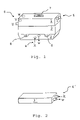
- FIG. 1 is a perspective view of a power electronic unit having a carrier which at the same time forms a heat sink,
- FIG. 2 is a perspective view of a further embodiment of a lower part of a carrier in the form of a heat sink,
- FIG. 3 is a bottom a view of a carrier which a heat sink
- FIG. 4 is a longitudinal sectional view of part of an engine and a power electronic unit mounted on a carrier structure forming a cooler.
- FIG. 1 shows a power electronic unit 1 (preferably in or with a casing) which is supported on a carrier 2 , 3 .
- the carrier is preferably composed of an upper part 2 and a lower part 3 .
- the terms “upper” and “lower” relate here to the power electronic unit 1 .
- the upper part 2 is arranged between the power electronic unit 1 and the lower part 3 .
- the lower part 3 of the carrier includes coolant channels 4 , for feeding in and carrying away a coolant, the coolant being preferably extracted from an engine cooling circuit, a cylinder block and/or a cylinder head of an internal combustion engine (not illustrated). The coolant is fed back to the cooling circuit after passing through the carrier 2 , 3 .
- coolant for example a gas, such as air
- other cooling circuits for example to a low-temperature flow circuit which is provided in the internal combustion engine
- the feeding in of coolant is indicated in FIG. 1 and in the further figures by an arrow which is designated by “k”.
- the carrying away of the coolant is indicated in FIG. 1 and in the further figures by an arrow which is designated by “w”.
- the upper part 2 of the carrier is preferably a cooler. It may be provided with attachment means 8 which may be eyelets by way of which the carrier and the power electronic unit 1 are mounted to the internal combustion engine, in particular to the engine block.
- the attachment means B are preferably arranged where the upper part 2 of the carrier adjoins the lower part 3 of the carrier. It is of course possible for the attachment means also to be provided on the lower part 3 of the carrier, in particular where the lower part 3 of the carrier adjoins the upper part 2 of the carrier and forms an adapter plate.
- the carrier with the power electronic unit 1 is preferably attached to the internal combustion engine at the location or at the attachment points at which an alternator or a standard generator is usually mounted.
- the lower part or adapter plate 3 includes passages 4 for supplying coolant from a particular engine to the upper part or cooler 2 .
- the power electronic unit 1 has terminals 5 for connection to an electric power supply (not illustrated), in particular an energy accumulator, for example a 12 volt and/or a 42 volt energy accumulator such as a battery. Furthermore, the power electronic unit 1 has terminals 6 supplying electric power to an electric machine (not illustrated) which preferably can be used as a starter/generator.
- the electric machine is preferably a three-phase machine, and by way of example three phases 6 (U, V, W) are illustrated in FIGS. 1 and 4 .
- the power electronic unit 1 has a control signal connection 7 via which control signals or regulating signals are fed to the power electronic unit 1 , and measurement variables or state variables can be transmitted by the power electronic unit 1 .
- the control signals or regulating signals are determined by a control unit (not illustrated) of the internal combustion engine and/or the motor vehicle and are transmitted to the control signal connection 7 .
- the measurement variables or state variables of the power electronic unit 1 are preferably evaluated by the control unit and used as the basis for determining the control signals.
- connections 5 , 6 , 7 are arranged so as to be easily accessible for mounting and servicing.
- FIG. 2 shows an alternative embodiment of the lower part 3 ′ of the carrier.
- lines or line connections are provided laterally on the lower part 3 in order to circulate coolant through the cooler.
- the electronic unit 1 may be a standard part.
- the carrier 2 , 3 comprises a cooler 2 and an adapter plate 3 with a coolant inlet and a coolant outlet 4 . It can comprise an upper part 2 , which s preferably provided with attachment means 8 , and a lower adapter plate part 3 for connection to the cooling circuit of the internal combustion engine, preferably the engine block.
- the carrier 2 , 3 can of course also be a single part, wherein the upper part 2 and the lower part 3 are combined in a single part which is designed for a particular engine.
- FIG. 3 is a bottom view of the carrier 2 , 3 .
- the carrier 2 , 3 particularly the lower part 3 , is preferably supported in a positively engaging fashion on the engine block of the internal combustion engine.
- the lower part 3 of the carrier may be in the form of a truncated pyramid or an obelisk, in which the larger base surface adjoins the upper part 2 , and the smaller cover surface has openings 4 for feeding in and carrying away coolant. Seals 9 , in particular seal rings, are provided on the edges of the openings 4 .
- the attachment means 8 are provided at freely accessible sides of the carrier 2 , 3 adjacent the power electronic unit 1 on which preferably no current or voltage feed in connections 5 , 6 and/or no signal connections 7 are provided.
- FIG. 4 illustrates a longitudinal section through a drive arrangement according to the invention with an internal combustion engine 10 and a power electronic unit 1 which is arranged on a carrier 2 , 3 .
- the internal combustion engine 10 preferably has coolant supply and return passages 11 , said passages 11 being part of a cooling circuit of the internal combustion engine. These passages 11 are aligned with the passages 4 of the carrier 2 , 3 for conducting the coolant to and out of the carrier 2 .
- different adapter plates 3 are provided with coolant passages 4 arranged so as to fit the coolant passages 11 of the particular engine.
- a seal 9 in particular seal rings, is arranged between the carrier 2 , 3 and the engine 10 for sealing the feed and carrying away coolant through the coolant passages 11 (that is to say between the carrier 2 , 3 and the engine block)
- the attachment means 8 are preferably disposed in recesses in the engine block 10 . These recesses are preferably suitable for holding screws or corresponding attachment means extending through the attachment means 8 which are preferably in the form of eyelets.
- Condensers 12 are illustrated with semiconductor elements which are arranged in the power electronic unit 1 and which project into the upper part 2 —configured as a cooler—of the carrier.
- the upper part 2 of the carrier preferably has lines/channels/deflection means 13 , in particular passages, which adjoin the channels 4 for feeding in and/or carrying away coolant. They provide for the cooling of the power electronic unit 1 or the semiconductor elements arranged on it and the electrical lines (illustrated for example by means of the capacitors 12 ), which are routed correspondingly.
- the capacitors 12 are preferably surrounded by the lines 13 .
- the coolant channels 4 , 13 which extend in the carrier 2 , 3 are illustrated by dash-dotted lines in FIG. 4 .
- the transitions between the upper part 2 of the carrier and the lower part 3 and the attachment means 8 are illustrated by means of dotted lines.
Landscapes
- Engineering & Computer Science (AREA)
- Microelectronics & Electronic Packaging (AREA)
- Physics & Mathematics (AREA)
- Thermal Sciences (AREA)
Abstract
Description
Claims (5)
Applications Claiming Priority (2)
| Application Number | Priority Date | Filing Date | Title |
|---|---|---|---|
| DEP802881/US/1 | 2003-03-14 | ||
| DE10311644A DE10311644A1 (en) | 2003-03-14 | 2003-03-14 | Motor vehicle drive comprises combustion engine and power electronics for control of electric machinery, with a support for the power electronics also acting as a heat sink, which is cooled by the engine coolant circuit |
Publications (2)
| Publication Number | Publication Date |
|---|---|
| US20040206313A1 US20040206313A1 (en) | 2004-10-21 |
| US7055468B2 true US7055468B2 (en) | 2006-06-06 |
Family
ID=32892284
Family Applications (1)
| Application Number | Title | Priority Date | Filing Date |
|---|---|---|---|
| US10/801,181 Expired - Fee Related US7055468B2 (en) | 2003-03-14 | 2004-03-13 | Drive arrangement for a motor vehicle |
Country Status (2)
| Country | Link |
|---|---|
| US (1) | US7055468B2 (en) |
| DE (1) | DE10311644A1 (en) |
Cited By (2)
| Publication number | Priority date | Publication date | Assignee | Title |
|---|---|---|---|---|
| US20090151657A1 (en) * | 2007-09-17 | 2009-06-18 | Wolfgang Doll | Coolant circuit for controlling the temperature of a cooling fluid and motor vehicle therewith |
| USD673618S1 (en) * | 2011-05-27 | 2013-01-01 | Paul Harper | Video game console accessory protective cover |
Families Citing this family (3)
| Publication number | Priority date | Publication date | Assignee | Title |
|---|---|---|---|---|
| FR2946220B1 (en) * | 2009-05-29 | 2011-05-20 | Peugeot Citroen Automobiles Sa | ELECTRIC POWER TRANSFER DEVICE FOR MOTOR VEHICLE AND ELECTRIC OR PARTIALLY ELECTRIC VEHICLE EQUIPPED WITH SUCH A DEVICE |
| US8488321B2 (en) * | 2011-10-10 | 2013-07-16 | Delphi Technologies, Inc. | Assembly for liquid cooling electronics by direct submersion into circulated engine coolant |
| US9291097B2 (en) * | 2013-06-04 | 2016-03-22 | Caterpillar Inc. | Cooling module for electronic engine components |
Citations (10)
| Publication number | Priority date | Publication date | Assignee | Title |
|---|---|---|---|---|
| US4763611A (en) * | 1985-11-22 | 1988-08-16 | Diesel Kiki Co., Ltd. | Electronically controlled fuel injection pump |
| US4893590A (en) * | 1987-09-30 | 1990-01-16 | Hitachi, Ltd. | Automotive liquid-cooled electronic control apparatus |
| US4951636A (en) * | 1988-11-28 | 1990-08-28 | Walbro Corporation | Constant pressure-differential fuel injection system |
| US5207186A (en) * | 1991-01-28 | 1993-05-04 | Sanshin Kogyo Kabushiki Kaisha | Arrangement for mounting an electronic control unit on an engine |
| DE19913450A1 (en) | 1999-03-25 | 2000-09-28 | Mannesmann Sachs Ag | Power electronics for controlling electrical power machine performance/power section with capacitors connecting splint rings and screw joints while the lid connects to the housing with connections to the cooling device |
| DE10009521A1 (en) | 2000-02-29 | 2001-08-30 | Mannesmann Sachs Ag | Electrical system has parts of electrical component(s) and/or controler(s) to be cooled connected into conditioning system coolant circuit with e.g. compressor, condenser, evaporator |
| US6396692B1 (en) * | 2000-07-27 | 2002-05-28 | Motorola, Inc. | Electronic control unit with integrated cooling module |
| US6604494B2 (en) * | 1998-11-24 | 2003-08-12 | Bombardier Motor Corporation Of America | Water-cooled engine control |
| US6644249B2 (en) * | 2001-02-07 | 2003-11-11 | Denso Corporation | Cooling mechanism for engine electronic control module |
| US6655326B2 (en) * | 1999-12-21 | 2003-12-02 | Cummins Engine Company, Ltd. | ECU temperature control |
-
2003
- 2003-03-14 DE DE10311644A patent/DE10311644A1/en not_active Withdrawn
-
2004
- 2004-03-13 US US10/801,181 patent/US7055468B2/en not_active Expired - Fee Related
Patent Citations (11)
| Publication number | Priority date | Publication date | Assignee | Title |
|---|---|---|---|---|
| US4763611A (en) * | 1985-11-22 | 1988-08-16 | Diesel Kiki Co., Ltd. | Electronically controlled fuel injection pump |
| US4893590A (en) * | 1987-09-30 | 1990-01-16 | Hitachi, Ltd. | Automotive liquid-cooled electronic control apparatus |
| US4951636A (en) * | 1988-11-28 | 1990-08-28 | Walbro Corporation | Constant pressure-differential fuel injection system |
| US5207186A (en) * | 1991-01-28 | 1993-05-04 | Sanshin Kogyo Kabushiki Kaisha | Arrangement for mounting an electronic control unit on an engine |
| US6604494B2 (en) * | 1998-11-24 | 2003-08-12 | Bombardier Motor Corporation Of America | Water-cooled engine control |
| US6694929B2 (en) * | 1998-11-24 | 2004-02-24 | Bombardier Motor Corporation Of America | Water-cooled engine control |
| DE19913450A1 (en) | 1999-03-25 | 2000-09-28 | Mannesmann Sachs Ag | Power electronics for controlling electrical power machine performance/power section with capacitors connecting splint rings and screw joints while the lid connects to the housing with connections to the cooling device |
| US6655326B2 (en) * | 1999-12-21 | 2003-12-02 | Cummins Engine Company, Ltd. | ECU temperature control |
| DE10009521A1 (en) | 2000-02-29 | 2001-08-30 | Mannesmann Sachs Ag | Electrical system has parts of electrical component(s) and/or controler(s) to be cooled connected into conditioning system coolant circuit with e.g. compressor, condenser, evaporator |
| US6396692B1 (en) * | 2000-07-27 | 2002-05-28 | Motorola, Inc. | Electronic control unit with integrated cooling module |
| US6644249B2 (en) * | 2001-02-07 | 2003-11-11 | Denso Corporation | Cooling mechanism for engine electronic control module |
Cited By (2)
| Publication number | Priority date | Publication date | Assignee | Title |
|---|---|---|---|---|
| US20090151657A1 (en) * | 2007-09-17 | 2009-06-18 | Wolfgang Doll | Coolant circuit for controlling the temperature of a cooling fluid and motor vehicle therewith |
| USD673618S1 (en) * | 2011-05-27 | 2013-01-01 | Paul Harper | Video game console accessory protective cover |
Also Published As
| Publication number | Publication date |
|---|---|
| US20040206313A1 (en) | 2004-10-21 |
| DE10311644A1 (en) | 2004-09-23 |
Similar Documents
| Publication | Publication Date | Title |
|---|---|---|
| US12162343B2 (en) | Drive module with improved efficiency | |
| US7855887B2 (en) | Inverter unit | |
| US8011467B2 (en) | Vehicle power supply system | |
| CA2593727C (en) | Drive for a vehicle, especially a tracked vehicle or a vehicle with wheel-based steering | |
| EP2326827B1 (en) | Electrical machine | |
| EP3193433A1 (en) | Vehicular rotating electrical machine apparatus | |
| US20070188119A1 (en) | Control device integrated dynamo-electric machine | |
| US8662225B2 (en) | Built-in equipment for micro-hybrid device for automotive vehicle and micro-hybrid device comprising the same | |
| US20060096795A1 (en) | Hybrid driving system for a motor vehicle | |
| CN110692189A (en) | Motor vehicle and converter device for motor vehicle | |
| KR20030081524A (en) | Fluid cooled electric machine | |
| US7423342B2 (en) | Method for assembling semiconductor switching elements and heat sink in rotary electric machine and rotary electric machine | |
| JP2008543260A (en) | Signal interconnection components for rotating electrical equipment | |
| JP5328147B2 (en) | Power drive unit | |
| GB2289581A (en) | Alternator and static converter system | |
| JP2008253041A (en) | Motor drive device | |
| US7055468B2 (en) | Drive arrangement for a motor vehicle | |
| JP2006177214A (en) | Electric compressor | |
| JP2021097524A (en) | Power conversion device | |
| JP3815885B2 (en) | Pump device | |
| CN114430239B (en) | Power module, inverter with power module, and electric drive with inverter | |
| US11338670B2 (en) | Transmission with power electronics module | |
| US12342510B2 (en) | Electrical switching device, electrical drive layout and motor vehicle | |
| JP2022161294A (en) | Mechatronic device | |
| Leonarski et al. | Motor-Integrated Segmented Inverters |
Legal Events
| Date | Code | Title | Description |
|---|---|---|---|
| AS | Assignment |
Owner name: DAIMLERCHRYSLER AG, GERMANY Free format text: ASSIGNMENT OF ASSIGNORS INTEREST;ASSIGNORS:SCHONDELMALER, ANDREAS;SUNDHELM, DIRK;REEL/FRAME:015462/0797;SIGNING DATES FROM 20040310 TO 20040312 |
|
| AS | Assignment |
Owner name: DAIMLER AG, GERMANY Free format text: CHANGE OF NAME;ASSIGNOR:DAIMLERCHRYSLER AG;REEL/FRAME:022846/0912 Effective date: 20071019 Owner name: DAIMLER AG,GERMANY Free format text: CHANGE OF NAME;ASSIGNOR:DAIMLERCHRYSLER AG;REEL/FRAME:022846/0912 Effective date: 20071019 |
|
| FPAY | Fee payment |
Year of fee payment: 4 |
|
| REMI | Maintenance fee reminder mailed | ||
| LAPS | Lapse for failure to pay maintenance fees | ||
| STCH | Information on status: patent discontinuation |
Free format text: PATENT EXPIRED DUE TO NONPAYMENT OF MAINTENANCE FEES UNDER 37 CFR 1.362 |
|
| STCH | Information on status: patent discontinuation |
Free format text: PATENT EXPIRED DUE TO NONPAYMENT OF MAINTENANCE FEES UNDER 37 CFR 1.362 |
|
| FP | Lapsed due to failure to pay maintenance fee |
Effective date: 20140606 |