US7038406B2 - Bi-directional field control for proportional control based generator/alternator voltage regulator - Google Patents
Bi-directional field control for proportional control based generator/alternator voltage regulator Download PDFInfo
- Publication number
- US7038406B2 US7038406B2 US10/360,411 US36041103A US7038406B2 US 7038406 B2 US7038406 B2 US 7038406B2 US 36041103 A US36041103 A US 36041103A US 7038406 B2 US7038406 B2 US 7038406B2
- Authority
- US
- United States
- Prior art keywords
- operably connected
- output
- signal
- switch
- input
- Prior art date
- Legal status (The legal status is an assumption and is not a legal conclusion. Google has not performed a legal analysis and makes no representation as to the accuracy of the status listed.)
- Expired - Lifetime, expires
Links
Images


Classifications
-
- H—ELECTRICITY
- H02—GENERATION; CONVERSION OR DISTRIBUTION OF ELECTRIC POWER
- H02P—CONTROL OR REGULATION OF ELECTRIC MOTORS, ELECTRIC GENERATORS OR DYNAMO-ELECTRIC CONVERTERS; CONTROLLING TRANSFORMERS, REACTORS OR CHOKE COILS
- H02P9/00—Arrangements for controlling electric generators for the purpose of obtaining a desired output
- H02P9/14—Arrangements for controlling electric generators for the purpose of obtaining a desired output by variation of field
- H02P9/26—Arrangements for controlling electric generators for the purpose of obtaining a desired output by variation of field using discharge tubes or semiconductor devices
- H02P9/30—Arrangements for controlling electric generators for the purpose of obtaining a desired output by variation of field using discharge tubes or semiconductor devices using semiconductor devices
- H02P9/305—Arrangements for controlling electric generators for the purpose of obtaining a desired output by variation of field using discharge tubes or semiconductor devices using semiconductor devices controlling voltage
Definitions
- This invention is related to the field of voltage control. More particularly, it is related to the field of controlling a generator/alternator made with a permanent magnetic field.
- the invention comprises a method of controlling voltage using bi-directional field excitation current, comprising the steps of measuring a field driver control signal's pulse width by counting a number of clock cycles that occur when the field driver control signal is high, determining whether the field driver control signal's duty cycle is above or below a threshold by comparing a bit count, supplying reverse field current if the field driver control signal FD duty cycle falls below a reverse direction threshold, and supplying forward field current if the field drive duty cycle exceeds the threshold.
- the step of supplying reverse field current further comprises the steps of turning a first switch on and pulse width modulating a second switch on and off, whereby reverse current is supplied to a rotor and generator output is decreased and whereby the effects of permanent magnets are nulled.
- the step of supplying forward field current further comprises the steps of turning a third switch on and turning a fourth switch on and off with a duty cycle corresponding to the field driver control signal's duty cycle, whereby forward current is supplied to the rotor and the generator output is increased.
- the invention comprises a voltage regulator, comprising a logic block, a controller having a field driver control output operably connected to a first input of the logic block, an H-bridge, a drive block operably connected between the H-bridge and the logic block, and a power train control module operably connected between the controller and the drive block.
- the H-bridge comprises a first pair of switches, comprising a first and a second switch connected in series, a second pair of switches, comprising a third and a fourth switch connected in series, wherein the first and second pair of switches are operably connected in parallel across a power source; and a rotor is operably connected between the series connections of the first and second pair of switches.
- the logic block comprises a counter having an output, whereby a number of clock cycles that occur when a field driver control signal is high is counted and a comparator, whereby the output from the counter is compared to a threshold.
- the driver block comprises a mode signal input and a pulse width modulation input operably connected to corresponding outputs of the logic block, a first output signal operably connected to a control input of the first switch, whereby the first switch is on when the mode signal is high, a second output operably connected to a control input of the second switch, whereby the second switch is pulse modulated on and off when the mode signal is high, a third output signal operably connected to a control input of the third switch, whereby the third switch is on when the mode signal is low; and a fourth output operably connected to a control input of the fourth switch, whereby the fourth output signal's duty cycle equals the field driver control signal's duty cycle when the mode signal is low.
- the power control module comprises an output operably connected to an input of the controller, whereby a pulse width modulated signal is transmitted to the controller and an input is operably connected to an output of the logic block, whereby the power control module receives a torque demand signal.
- FIG. 1 is a view of the rotor of the present invention.
- FIG. 2 is a plot of generator/alternator output in amps vs. speed in RPM where permanent magnets are embedded in the rotor;
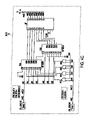
- FIG. 3 is part of a block diagram of a generator/alternator voltage regulator used for bi-directional field excitation
- FIG. 4A is a logic block of a part of a logic block diagram of the bi-directional field control logic of the permanent magnet voltage control field-reversing regulator;
- FIG. 4B is a logic block of a logic block diagram of the bi-directional field control logic of the permanent magnet voltage control field-reversing regulator
- FIG. 4C is a logic block of a logic block diagram of the bi-directional field control logic of the permanent magnet voltage control field-reversing regulator
- FIG. 4D is a logic block of a logic block diagram of the bi-directional field control logic of the permanent magnet voltage control field-reversing regulator
- FIG. 4E is a logic block of a logic block diagram of the bi-directional field control logic of the permanent magnet voltage control field-reversing regulator
- FIG. 4F is a logic block of a logic block diagram of the bi-directional field control logic of the permanent magnet voltage control field-reversing regulator
- FIG. 4G is a logic block of a logic block diagram of the bi-directional field control logic of the permanent magnet voltage control field-reversing regulator
- FIG. 4H is a logic block of a logic block diagram of the bi-directional field control logic of the permanent magnet voltage control field-reversing regulator.
- FIG. 5 illustrates a succession of increasing pulse widths for signal QRL.
- This disclosure describes an H-bridge power switching control method that interfaces with an existing proportional control based automotive generator/alternator voltage regulator. It controls rotating machines that use rotors supplemented with permanent magnets that would otherwise have uncontrolled voltage levels without the bi-directional field current that the H-bridge provides.
- a generator/alternator made with a permanent magnetic field 1) voltage, control via rectification; 2) voltage control via a DC-DC converter; and 3) voltage control via bi-directional field excitation current.
- the present invention uses the third method.
- the present invention comprises a method of monitoring the uni-directional field control duty cycle as a means of determining if the system voltage is rising and going out of control. If the system voltage exceeds a voltage range, the logic then provides reverse field current in a pulse width modulation (PWM) fashion to null the effects of the permanent magnets.
- PWM pulse width modulation
- Permanent magnets (PM) 10 (shown in FIG. 1 ) are used in rotors 15 to produce a high output level at low speeds. This difference can be seen in FIG. 2 where the output of a generator/alternator (measured in amps) is plotted against engine speed in rpm for a rotor 15 containing permanent magnets 25 and for one that does not have permanent magnets (PM) 30 . The currents were measured at 25 deg C. For an operating speed of 2,000 rpm, there is an over 50 Amp difference in output current. Thus, using permanent magnets, the alternator will produce a full rated output at low speeds. However, as the rpm of the alternator increases, the magnetic flux from the magnets 10 produces an even greater output.
- One class of generator voltage regulators uses proportional control for maintaining the desired system voltage.
- Either a low-side or a high-side field excitation driver is used to control the rotor's 15 average field current.
- the driver operates at a constant switching period and variable duty-cycle.
- a regulator with either a low-side or high-side field drive can not adequately control a generator with permanent magnets embedded in its rotor because excessive system voltage is possible at low electrical loads and sufficient rotational speed as discussed above.
- An H-bridge switching topology for bi-directional field excitation is required to null, when desired, the effects of the rotor's 15 permanent magnets 10 (i.e., magnetic field is governed by current polarity).
- the present invention uses both a low-side and a high-side field excitation driver to control the rotor's 15 average field current.
- the standard proportional control signal for generators/alternators using uni-directional field excitation can control an H-bridge for bi-directional field excitation (see FIG. 3 ).
- the logic uses a field driver control signal's duty cycle 66 to determine whether to supply forward or reverse field current is applied to the rotor 15 .
- the present invention also compares the field drive control signal's duty cycle 66 to a threshold a predetermined number of times to filter out duty-cycle noise before supplying reverse field current. Reverse field current will generate a flux to oppose the flux generated by the magnets 10 , thus reducing output voltage to a desired level.
- FIG. 3 is a block diagram of a generator voltage regulator 40 used for bi-directional field excitation.
- the Externally-Controlled Integral Alternator Regulator (ECIAR) block 45 is the proportional controller for standard uni-directional field excitation.
- the ECIAR 45 is an application specific integrated circuit (ASIC) used in Visteon voltage regulators.
- ASIC application specific integrated circuit
- the power train control module (PCM) 50 determines the set point voltage.
- the power train control module (PCM) 50 can infer the lead acid battery temperature based on the power train control module's sensor inputs and logic to determine an appropriate charging system voltage.
- the ECIAR's inputs are AP (generator B+output) 52 , SNS (external battery sense) 54 , RC (voltage set point communication input signal alt_com which is received from the power train control module 50 ) 56 , STA (stator winding input for rotational speed sensing) 58 and CL (input from current sense element for excessive field current protection) 60 .
- the SNS input 54 is connected to the positive terminal of the lead-acid battery 62 in order to sense the voltage of the battery 62 .
- the STA input 58 is connected to one winding of the stator 59 to sense rotational speed.
- the stator is connected to a rectifier 61 .
- a fault is indicated.
- the RC input 56 is used to wake up the ECIAR 45 .
- the ECIAR 45 goes into a quiescent state when the vehicle is not being operated and the charging system is not needed.
- ECIAR 45 wakes up when it sees the pulse width modulated signal alt_com 55 provided by the power train control module (PCM) 50 .
- PCM power train control module
- the ECIAR's 45 outputs are FD (field driver control signal) 66 and Load Indicator LI 68 (fault indication and FD duty-cycle signal input for power train control module).
- the field driver control signal output FD 66 is a signal whose duty cycle is indicative of the system voltage.
- the load indicator output LI 68 has the ability to sink output, thereby having the ability to provide a “low” output to the LOGIC block 70 . By providing a “low” continuously, the ECIAR 45 indicates that a charging system fault has been detected by the PM voltage control regulator 40 .
- the LOGIC block 70 is the bi-directional field excitation controller for the H-bridge 72 . Its inputs are FD 66 , LI 68 , and information from a temperature sense element 74 . The outputs are the four signals required to control each of the four switches that comprise the H-bridge 72 or a field excitation direction and intensity signal (i.e., direction and pwm respectively).
- a DRIVE block 76 interfaces the LOGIC block 70 with the H-bridge 72 in order to properly bias the power switches (e.g., n-channel enhancement MOSFETs). Included in the LOGIC block 70 are the necessary bias circuitry, level shifters and clock signal to implement the digital functions.
- the LOGIC block 70 is a programmable logic device (PLD).
- PLD programmable logic device
- the DRIVE block 76 can include charge pumps for high-side field drive.
- the DRIVE block 76 can be an off-the-shelf H-Bridge power MOSFET controller commonly used for DC motor control.
- the H-bridge 72 consists of a first pair of power switches SW 1 and SW 2 and another pair of power switches SW 3 and SW 4 .
- the switches are n-channel MOSFETs.
- Devices SW 1 and SW 3 have their drain terminals connected to the positive terminal of a power supply in the form of a lead acid battery 62 .
- a vehicle load 63 is also connected to the positive terminal.
- Devices SW 1 and SW 3 have their sources connected to the drains of devices SW 4 and SW 2 respectively.
- the sources of SW 4 and SW 2 are connected to ground potential through resistor R 1 and to the current sense input CL 60 of the ECIAR block 45 which receives input from the current sense element R 1 for detecting excessive field current.
- Each of the switches SW 1 and SW 3 is shunted between the drain and source terminals by flyback diodes D 1 and D 3 , respectively, which are polarized oppositely with respect to the drain-source junction.
- the switches SW 4 and SW 2 have their drain terminals and source terminals connected through opposite-polarized flyback diodes D 4 and D 2 , respectively.
- a rotor winding represented by 15 is connected between the drain terminals of power control devices SW 4 and SW 2 .
- the driver stage configuration in which two pair of series connected power switches are connected in parallel across a power source, with rotor 15 connected between the junction of switches SW 1 and SW 4 and the junction of switches SW 3 and SW 2 is called an “H-bridge” configuration.
- FIGS. 4A to 4H are block diagrams of the bi-directional field control logic. It is a graphical description of the logic functions implemented using a programmable logic device (PLD).
- Blocks 90 , 100 , and 110 are located in the LOGIC block 70 .
- the LOGIC block 70 receives signals in Block 90 indicative of the operational state of the generator/alternator, compares the signal in Block 100 with reference signals from block 10 representing the desired operational states and produces PWM command and field current direction command signals causing the alternator/generator to operate as desired.
- the DRIVE block 76 ( FIG. 3 ) responds to the pwm and direction commands from the LOGIC block 70 to produce operating signals for controlling the switches.
- the Drive block 76 produces signals to activate switches SW 1 and SW 2 or SW 3 and SW 4 depending on which field current direction is needed to maintain voltage regulation.
- Block 90 it is seen that the LOGIC block's PLD main input is the eciar_fd_bar signal. It is the inverse of the ECIAR's field driver control signal FD 66 because the field driver control signal FD 66 is level shifted for programmable logic device PLD compatibility.
- Block 90 monitors the uni-directional field control duty cycle as a means of determining if the system voltage is rising and going out of control.
- An advantage of using the field control duty cycle to monitor system voltage as opposed to other methods of monitoring system voltage is that this method avoids having to use an additional voltage comparator.
- the proportional controller in the ECLAR 45 uses a voltage comparator and it is difficult to implement an additional comparator to track its operation without introducing offset errors that lead to regulation inaccuracies.
- block 90 measures the field driver control signal's FD 66 pulse width. This essentially determines the field excitation duty-cycle. It does this by counting the number of clock cycles that occur when the field driver control signal FD 66 is high.
- the ECIAR's 45 main timer is also 16 kHz. Therefore, the logic implemented in the LOGIC block 70 PLD can easily migrate into a new regulator ASIC based on the ECIAR 45 design.
- the master clock in the programmable logic device PLD implementation enables a synchronous logic system and, therefore, avoids meta-stable logic states.
- the field driver control signal FD 66 pulse width is the up counter's value in block A (q[7 . . . 0] from “my_counter”) times the clock period (i.e., 1/16 kHz).
- Block 100 determines if the field drive control signal's FD 66 duty-cycle is either above or below a threshold level set by block 110 . It does this by using a comparator, my_compare_low, to compare the 8-bit count determined by block 90 with an adjustable 8-bit limit set by block 110 .
- the 8-bit limit depends on the initial state of the field driver control signal's FD's 66 pulse width—that is, if the field driver control signal FD's 66 pulse width, as determined by block 90 's 8-bit word (i.e., q[7 . . . 0] from “my_counter”) is above the threshold, then the threshold is win[6.0] (i.e., a 7-bit setting).
- the threshold increases by hys[3 . . . 0] (i.e., a 4-bit setting) when the pulse count is below the threshold.
- hys[3 . . . 0] i.e., a 4-bit setting
- This is essentially an adjustable digital threshold with hysteresis. It determines when the field current direction is reversed so that it no longer flows in the direction aiding generator output.
- the mode signal 75 (or direction signal in FIG. 3 ) controls the direction of the supply current (forward or reverse) supplied by the H-bridge 72 .
- the mode signal 75 is set high and a pulse is triggered (i.e., rd_trigger) if the field drive duty-cycle falls below the reverse direction threshold.
- the mode signal 75 is set low and a different pulse is triggered (i.e., fd_trigger) when the field driver control signal's FD 66 duty cycle exceeds the threshold with hysteresis. These signals are used to control the on/off state of the H-bridge power devices, SW 1 –SW 4 .
- the mode signal 75 controls the direction of the field current supplied to the rotor 15 .
- an extra event filter can be added to block 100 that can adequately determine the “forward” to “reverse” field drive transition.
- mode is set high as soon as the field driver control signal's FD 66 duty cycle falls below the threshold window.
- An alternative method is to set mode high only after the field driver control signal's FD 66 duty cycle falls below the threshold window after a predetermined consecutive number of times. This filters field drive duty-cycle noise and provides a delay to distinguish system set point changes from either load or speed changes.
- a low-duty-cycle i.e., ⁇ 20%) for an extended period is an indication that the system voltage is above its target value. This is the indication needed to invoke a field polarity that opposes the permanent magnets.
- a reverse field current is applied to the rotor 15 .
- the field driver control signal's FD's 66 duty-cycle will then begin to increase as the system voltage decreases under the influence of a “reverse” field polarity.
- a moderate field duty-cycle e.g., >20%) indicates that the field may be aided by the permanent magnets 10 .
- Blocks 120 , 130 , 140 , and 150 are located in the Drive block 76 .
- Blocks 120 , 130 , 140 , and 150 produce commands for activating switches SW 1 and SW 2 or switches SW 3 and SW 4 depending on the direction or mode command signal 75 , i.e., whether it is desired to supply reverse or forward current to the circuit.
- the gate terminals of MOSFETs SW 1 thru SW 4 act as control inputs.
- Block 120 controls the on/off state of switch SW 4 in the H-bridge 72 so that the field current increases the generator's output or electromotive force.
- Output signal QFL 78 gates switch SW 4 on and off.
- the output of the AND gate is signal QFL 78 .
- signal QFL's 78 duty cycle equals the ECLAR's 45 field driver control signal FD 66 duty-cycle so long as the mode signal 75 is low.
- switch SW 4 is gated on and off with a duty cycle corresponding to the field driver control signal FD 66 duty-cycle.
- QFL 78 is held low (turning switch SW 4 off completely) if the mode signal 75 is high (i.e., only reverse field current needed). That is the field current direction is reversed so that it no longer flows in the direction aiding generator output. This circumvents the minimum field excitation duty-cycle inherent in the existing ECIAR design (i.e., a small amount of field current flows even if the system voltage is above the desired set point).
- Block 130 outputs signal QFH 80 to control the corresponding power device in the H-bridge (switch SW 3 ) so that field current increases the generator's output.
- QFH 80 is high (turning switch SW 3 on) as long as the mode signal 75 is low.
- controls signals QFL 78 and QFH 80 gate switches SW 3 and SW 4 to supply field current to the motor to increase the generator output.
- switch SW 3 is on and switch SW 4 pulses on and off corresponding to the field driver control signal's FD 66 duty-cycle to supply forward current to the rotor to increase generator output.
- forward field current flows from the positive terminal of the lead-acid battery 62 through switch SW 3 through the rotor through switch SW 4 through resistor R 1 to ground.
- QFH 80 is held low (turning switch SW 3 off completely) if the mode signal 75 is high (i.e., only reverse field current needed).
- the forward current conduction to the rotor 15 is controlled in accordance to the field driver control signal's FD 66 duty-cycle.
- Block 150 controls the on/off state of the power switch SW 2 in the H-bridge 72 using signal QRL 79 so that the field current decreases the generator's output or electromotive force. That is, reverse field current is supplied by the H-bridge 72 . It does this by setting up a magnetic field that opposes the magnetic field from the rotor's 15 permanent magnets 10 .
- Output signal QRL 79 is input to the gate of switch SW 2 . QRL 79 starts to pulse width modulate (PWM) when mode is set high. When the mode signal 75 goes logic HIGH, the S-R flip flop is enabled.
- PWM pulse width modulate
- the output of the flip flop, signal QRL 79 is switched between 0 and 1 with a pulse width and pulse repetition rate determined by a threshold value loaded into the comparator and input signal fd_edge.
- block 150 functions as a pulse width modulation circuit whose output signal, QRL 79 , gates switch SW 2 on and off.
- the PWM nulls the effects of the permanent magnets 10 by supplying current in a direction which opposes the current induced in the field windings by the magnets 10 .
- the PWM method allows for variations expected in the amount of reverse excitation needed to null the effects of the permanent magnets 10 by varying pulse width and pulse repetition frequency to vary the magnitude of the reverse current delivered to the circuit.
- Block 150 provides an increasing QRL 79 pulse width coincident with the ECIAR's 45 FD signal 66 so long as the mode signal 75 is high.
- the ECIAR 45 continues to produce an FD signal 66 at a low duty-cycle (i.e., 6.25%) at 125 Hz (typical) even if the system voltage is above set point and reverse field current is needed.
- the mode signal 75 enables block 150 's S-R flip flop.
- the ECIAR's FD signal 66 via fd_edge, sets the S-R flip-flop.
- An up and down counter (my_counter 4 and my_down_counter 1 respectively) reset the S-R flip-flop to effectively form a succession of increasing pulse widths (see FIG. 4 ).
- the up counter is incremented every 8 msec (typical) via fd_edge and the S-R flip-flop is reset when the down counter finishes counting down from the up counter's value.
- the up counter is allowed to continue counting upward until a preset value is reach as governed by my_compare 6 (a value corresponding to about 50% is typically needed as a reverse drive governor).
- QRL 79 is held low (turning switch SW 2 off completely) if the mode signal is low (i.e., only forward field current needed).
- Block 140 controls the corresponding power device SW 1 in the H-bridge 72 using signal QRH 77 so that the field current direction reverses.
- QRH 77 is high so long as mode is high, turning switch SW 1 on.
- switch SW 1 is on and switch SW 2 pulses on and off corresponding to the PWM characteristics to supply reverse current to the rotor to decrease generator output.
- reverse field current flows from the positive terminal of the lead-acid battery 62 through switch SW 1 through the rotor 15 through switch SW 2 through resistor R 1 to ground.
- controls signals QRH 77 and QRL 79 gate switches SW 1 and SW 2 to supply reverse field current to the rotor 15 to decrease the generator output.
- the reverse current conduction to the rotor 15 is controlled in accordance to the PWM signal.
- the magnitude of the reverse current supplied to the rotor 15 is proportional to the duty cycle of the PWM signal. As the duty cycle increases, the average current that is supplied increases.
- Blocks 130 and 140 control their corresponding H-bridge power devices so that there is a “make-before-brake” connection with the opposing device when mode changes state.
- the timing is adjustable so that there is maximum control over the field current recirculation during the “forward” to “reverse” field excitation transitions.
- blocks 120 , 130 , 140 and 150 can be reconfigured to provide only two signals as shown in FIG. 3 .
- the direction 75 and pwm signals 73 can then interface with a standard H-bridge MOSFET driver typically used for DC motor control.
- QFL 78 and QRL 79 do not necessarily need to control the low-side field drivers SW 4 and SW 2 as shown in FIG. 3 . They may control the high-side field drivers so long as QFH 80 and QRH 77 control the low-side drivers.
- Block 160 in FIG. 4H is located in the LOGIC block 70 . It is the logic needed to modify, if necessary, the ECIAR's 45 fault indication LI signal 68 .
- the power train control module (PCM) 50 determines the set point voltage. PCM's 50 output signal alt_com 55 is used to set the voltage set point.
- the PCM block 50 receives the alt_non input signal 64 from Block 160 of the LOGIC block 70 and uses it to infer the generator's torque demand on the internal combustion engine. It is also the voltage regulator's fault indication signal.
- Alt_non 64 is the same as LI signal 68 for generators using uni-directional field excitation and LI signal 68 , under non-fault conditions, reflects the field excitation duty-cycle (i.e, FD).
- alt_mon 64 can be the same as LI 68 in generators with bi-directional field excitation. However, if needed, Block 160 shows the logic that reflects the field excitation duty-cycle regardless of the field direction. It also maintains LI's 68 fault indication mode in the event that a temperature dependent fault signal, 74 , is provided.
- Block 110 This block provides the threshold value used to determine if the H-bridge 72 should be either assisting or nulling the rotor's 15 permanent magnets 10 . It is an 8-bit value whose magnitude is win( 6 . . . 0 ) when mode is low (i.e., ‘forward’ rotor current drive to increase generator/alternator output) and win( 6 . . . 0 ) plus hys( 3 . . . 0 ) when mode is high (i.e., ‘reverse’ rotor current drive to null the influence of the rotor's 15 permanent magnets 10 ).
- the end result is a digital threshold with hysteresis. A typical value for win( 6 . . .
- 0 14 which is effectively an 11% duty-cycle threshold when FD's duty-cycle is greater than this value and a typical value for win( 3 . . . 0 ) is 4 which effectively increases the threshold to 14% when FD's duty-cycle falls below 11%.
- Blocks 130 & 140 These blocks control the switching of the high-side drivers, or low-side drivers in an alternate implementation, so that the rotor's 15 field current is allowed to decay, due to its inductance, between mode transitions (i.e., switching field current direction from either ‘forward’ to ‘reverse’ or from ‘reverse’ to ‘forward’.) It operates much like the braking feature for motor control H-bridges.
- Block 130 controls SW 3 ; SW 3 is normally on when mode is low.
- Block 140 controls SW 1 ; SW 1 is normally on when mode is high.
- My_counter 3 and my_compare 3 in block 130 controls how quickly SW 3 turns-off when mode transitions from low to high (i.e., ‘reverse’ field current demanded).
- My_counter 3 and my_compare 5 in block 140 do the same for SW 1 for the case when mode transitions from high to low (i.e., ‘forward’ field current demanded).
- My_counter 3 and my_compare 2 in block 130 controls how long SW 3 waits to turn on when mode transitions from high to low.
- My_counter 3 and my_compare 4 in block 140 do the same for SW 1 for the case when mode transitions from low to high. This, in effect, allows the field current to recirculate through the diodes in parallel with the H-bridge 72 switches between mode transitions so that ‘forward’ current is allowed to decay before ‘reversing’ and ‘reverse’ current is allowed to decay before changing directions. The timing is adjusted to accommodate rotor inductance.
Abstract
Description
Claims (16)
Priority Applications (1)
| Application Number | Priority Date | Filing Date | Title |
|---|---|---|---|
| US10/360,411 US7038406B2 (en) | 2003-02-07 | 2003-02-07 | Bi-directional field control for proportional control based generator/alternator voltage regulator |
Applications Claiming Priority (1)
| Application Number | Priority Date | Filing Date | Title |
|---|---|---|---|
| US10/360,411 US7038406B2 (en) | 2003-02-07 | 2003-02-07 | Bi-directional field control for proportional control based generator/alternator voltage regulator |
Publications (2)
| Publication Number | Publication Date |
|---|---|
| US20040155632A1 US20040155632A1 (en) | 2004-08-12 |
| US7038406B2 true US7038406B2 (en) | 2006-05-02 |
Family
ID=32824007
Family Applications (1)
| Application Number | Title | Priority Date | Filing Date |
|---|---|---|---|
| US10/360,411 Expired - Lifetime US7038406B2 (en) | 2003-02-07 | 2003-02-07 | Bi-directional field control for proportional control based generator/alternator voltage regulator |
Country Status (1)
| Country | Link |
|---|---|
| US (1) | US7038406B2 (en) |
Cited By (48)
| Publication number | Priority date | Publication date | Assignee | Title |
|---|---|---|---|---|
| US20060076124A1 (en) * | 2004-09-07 | 2006-04-13 | Bahman Sharifipour | Apparatus for and method of cooling molded electronic circuits |
| US20070190848A1 (en) * | 2006-02-02 | 2007-08-16 | Xiaoyang Zhang | Power adaptor and storage unit for portable devices |
| US20070263415A1 (en) * | 2006-02-14 | 2007-11-15 | Arian Jansen | Two terminals quasi resonant tank circuit |
| US20080074095A1 (en) * | 2006-09-25 | 2008-03-27 | Telefus Mark D | Bi-directional regulator |
| US20080239760A1 (en) * | 2007-03-29 | 2008-10-02 | Mark Telefus | Primary only constant voltage/constant current (CVCC) control in quasi resonant convertor |
| US20080238389A1 (en) * | 2007-03-29 | 2008-10-02 | Mark Telefus | Primary only control quasi resonant convertor |
| US20090295531A1 (en) * | 2008-05-28 | 2009-12-03 | Arturo Silva | Optimized litz wire |
| US20090310384A1 (en) * | 2008-06-12 | 2009-12-17 | Bahman Sharifipour | AC-DC input adapter |
| US20100127737A1 (en) * | 2008-11-21 | 2010-05-27 | Flextronics Ap, Llc | Variable PFC and grid-tied bus voltage control |
| US20100142230A1 (en) * | 2007-01-16 | 2010-06-10 | Schroeder Genannt Berghegger Ralf | Simplified primary triggering circuit for the switch in a switched-mode power supply |
| US20100244753A1 (en) * | 2007-06-27 | 2010-09-30 | Farouk Boudjemai | Method and electric machine for braking a thermal engine of a vehicle during the stop phase thereof |
| US20100289466A1 (en) * | 2009-05-15 | 2010-11-18 | Flextronics Ap, Llc | Closed loop negative feedback system with low frequency modulated gain |
| US20100315839A1 (en) * | 2009-05-07 | 2010-12-16 | Zaohong Yang | Energy recovery snubber circuit for power converters |
| US20100322441A1 (en) * | 2009-06-23 | 2010-12-23 | Flextronics Ap, Llc | Notebook power supply with integrated subwoofer |
| US20110025286A1 (en) * | 2007-10-17 | 2011-02-03 | Power Systems Technologies Gmbh | Control Circuit For a Primary Controlled Switched Mode Power Supply with Improved Accuracy of the Voltage Control and Primary Controlled Switched Mode Power Supply |
| US7978489B1 (en) | 2007-08-03 | 2011-07-12 | Flextronics Ap, Llc | Integrated power converters |
| US20110203840A1 (en) * | 2010-02-23 | 2011-08-25 | Flextronics Ap, Llc | Test point design for a high speed bus |
| US8102678B2 (en) | 2008-05-21 | 2012-01-24 | Flextronics Ap, Llc | High power factor isolated buck-type power factor correction converter |
| US8279646B1 (en) | 2007-12-14 | 2012-10-02 | Flextronics Ap, Llc | Coordinated power sequencing to limit inrush currents and ensure optimum filtering |
| US8289741B2 (en) | 2010-01-14 | 2012-10-16 | Flextronics Ap, Llc | Line switcher for power converters |
| US8441810B2 (en) | 2010-11-09 | 2013-05-14 | Flextronics Ap, Llc | Cascade power system architecture |
| US8488340B2 (en) | 2010-08-27 | 2013-07-16 | Flextronics Ap, Llc | Power converter with boost-buck-buck configuration utilizing an intermediate power regulating circuit |
| US8520410B2 (en) | 2010-11-09 | 2013-08-27 | Flextronics Ap, Llc | Virtual parametric high side MOSFET driver |
| US8598725B1 (en) * | 2012-06-11 | 2013-12-03 | United Technologies Corporation | Utilizing flux controllable PM electric machines for wind turbine applications |
| US8654553B1 (en) | 2013-03-15 | 2014-02-18 | Flextronics Ap, Llc | Adaptive digital control of power factor correction front end |
| US8693213B2 (en) | 2008-05-21 | 2014-04-08 | Flextronics Ap, Llc | Resonant power factor correction converter |
| US20140125296A1 (en) * | 2011-06-08 | 2014-05-08 | Valeo Equipements Electriques Moteur | Method for controlling the resisting torque of a motor vehicle alternator, and system for implementing this method |
| US8743565B2 (en) | 2012-07-27 | 2014-06-03 | Flextronics Ap, Llc | High power converter architecture |
| US8842450B2 (en) | 2011-04-12 | 2014-09-23 | Flextronics, Ap, Llc | Power converter using multiple phase-shifting quasi-resonant converters |
| US8964413B2 (en) | 2010-04-22 | 2015-02-24 | Flextronics Ap, Llc | Two stage resonant converter enabling soft-switching in an isolated stage |
| US9019726B2 (en) | 2012-07-13 | 2015-04-28 | Flextronics Ap, Llc | Power converters with quasi-zero power consumption |
| US9019724B2 (en) | 2012-07-27 | 2015-04-28 | Flextronics Ap, Llc | High power converter architecture |
| US9093911B2 (en) | 2013-03-15 | 2015-07-28 | Flextronics Ap, Llc | Switching mode power converter using coded signal control |
| US9118253B2 (en) | 2012-08-15 | 2015-08-25 | Flextronics Ap, Llc | Energy conversion architecture with secondary side control delivered across transformer element |
| US9136769B2 (en) | 2012-10-10 | 2015-09-15 | Flextronics Ap, Llc | Load change detection for switched mode power supply with low no load power |
| US9184668B2 (en) | 2013-03-15 | 2015-11-10 | Flextronics Ap, Llc | Power management integrated circuit partitioning with dedicated primary side control winding |
| US9203293B2 (en) | 2012-06-11 | 2015-12-01 | Power Systems Technologies Ltd. | Method of suppressing electromagnetic interference emission |
| US9203292B2 (en) | 2012-06-11 | 2015-12-01 | Power Systems Technologies Ltd. | Electromagnetic interference emission suppressor |
| US9276460B2 (en) | 2012-05-25 | 2016-03-01 | Flextronics Ap, Llc | Power converter with noise immunity |
| US9287792B2 (en) | 2012-08-13 | 2016-03-15 | Flextronics Ap, Llc | Control method to reduce switching loss on MOSFET |
| US9323267B2 (en) | 2013-03-14 | 2016-04-26 | Flextronics Ap, Llc | Method and implementation for eliminating random pulse during power up of digital signal controller |
| US20160268942A1 (en) * | 2015-03-12 | 2016-09-15 | Hamilton Sundstrand Corporation | Control of Hybrid Permanent Magnet Machine With Rotating Power Converter and Energy Source |
| US9494658B2 (en) | 2013-03-14 | 2016-11-15 | Flextronics Ap, Llc | Approach for generation of power failure warning signal to maximize useable hold-up time with AC/DC rectifiers |
| US9605860B2 (en) | 2012-11-02 | 2017-03-28 | Flextronics Ap, Llc | Energy saving-exhaust control and auto shut off system |
| US9621053B1 (en) | 2014-08-05 | 2017-04-11 | Flextronics Ap, Llc | Peak power control technique for primary side controller operation in continuous conduction mode |
| US9660540B2 (en) | 2012-11-05 | 2017-05-23 | Flextronics Ap, Llc | Digital error signal comparator |
| US9711990B2 (en) | 2013-03-15 | 2017-07-18 | Flextronics Ap, Llc | No load detection and slew rate compensation |
| US11440397B2 (en) * | 2016-07-27 | 2022-09-13 | Avid Technology Limited | Electric machine |
Families Citing this family (7)
| Publication number | Priority date | Publication date | Assignee | Title |
|---|---|---|---|---|
| JP4254738B2 (en) * | 2005-03-31 | 2009-04-15 | 株式会社デンソー | Power generation control device for vehicle generator |
| US20070069521A1 (en) * | 2005-09-23 | 2007-03-29 | C.E. Niehoff & Co. | Power control system and method |
| DE102007019990B4 (en) * | 2007-04-27 | 2017-08-17 | Robert Bosch Gmbh | Car generator with external regulator |
| DE102010001247A1 (en) * | 2010-01-27 | 2011-07-28 | Robert Bosch GmbH, 70469 | Circuit arrangement for use in voltage regulator for reduction of current via inductor of generator in e.g. passenger car, has control unit controlling integrated circuits so that free wheeling of current is enabled via wheeling circuits |
| JP6565983B2 (en) * | 2016-09-12 | 2019-08-28 | 株式会社デンソー | Control device for rotating electrical machine |
| CN111277002B (en) * | 2020-03-19 | 2022-03-11 | 国网浙江省电力有限公司电力科学研究院 | Flexible excitation power unit parallel topology structure and control method thereof |
| DE102020120814A1 (en) | 2020-08-06 | 2022-02-10 | Seg Automotive Germany Gmbh | Method for checking a fast de-excitation path of an excitation circuit and corresponding excitation circuit |
Citations (30)
| Publication number | Priority date | Publication date | Assignee | Title |
|---|---|---|---|---|
| US3609514A (en) | 1970-07-27 | 1971-09-28 | Gen Motors Corp | Generator voltage regulator |
| US4471288A (en) | 1982-03-23 | 1984-09-11 | Mitsubishi Denki Kabushiki Kaisha | Apparatus for controlling charging generators |
| US4654551A (en) | 1985-05-20 | 1987-03-31 | Tecumseh Products Company | Permanent magnet excited alternator compressor with brushless DC control |
| US4710686A (en) | 1986-08-04 | 1987-12-01 | Guzik Technical Enterprises | Method and apparatus for control of current in a motor winding |
| US4794312A (en) | 1986-09-29 | 1988-12-27 | Hitachi, Ltd. | Method and apparatus for controlling a servo motor |
| US4973896A (en) | 1987-10-21 | 1990-11-27 | Toyo Densan Company, Ltd. | Automobile generator apparatus |
| US5036268A (en) | 1986-11-26 | 1991-07-30 | Dynawatt Oy | Procedure and apparatus for producing an a.c. voltage |
| US5038728A (en) * | 1988-05-25 | 1991-08-13 | Nutronics Corporation | Method & apparatus for managing alternator loads on engines |
| US5343382A (en) | 1993-04-05 | 1994-08-30 | Delco Electronics Corp. | Adaptive current control |
| GB2276050A (en) * | 1993-02-24 | 1994-09-14 | Dowty Defence & Air Syst | Control arrangement for permanent magnet machines |
| US5373196A (en) * | 1992-10-16 | 1994-12-13 | Vanner Weldon Inc. | Combination static/dynamic inverter |
| USRE35124E (en) | 1974-06-24 | 1995-12-19 | General Electric Company | Control system, electronically commutated motor system, draft inducer apparatus and method |
| US5481176A (en) * | 1994-07-05 | 1996-01-02 | Ford Motor Company | Enhanced vehicle charging system |
| US5502368A (en) | 1994-06-06 | 1996-03-26 | Ecoair Corp. | Hybrid alternator with voltage regulator |
| US5545971A (en) * | 1995-06-01 | 1996-08-13 | Gomez; Zaitter | AC voltage regulator |
| US5552651A (en) | 1995-07-03 | 1996-09-03 | General Motors Corporation | Alternating current generator |
| US5581172A (en) | 1993-12-28 | 1996-12-03 | Mitsubishi Denki Kabushiki Kaisha | Apparatus for controlling output of vehicular AC generator |
| US5656922A (en) | 1993-06-14 | 1997-08-12 | Ecoair Corp. | Vehicle based AC power system |
| US5663605A (en) | 1995-05-03 | 1997-09-02 | Ford Motor Company | Rotating electrical machine with electromagnetic and permanent magnet excitation |
| US5710741A (en) | 1994-03-11 | 1998-01-20 | Micron Technology, Inc. | Power up intialization circuit responding to an input signal |
| US5745534A (en) * | 1994-12-12 | 1998-04-28 | Ford Motor Company | Method and apparatus for data communication |
| US5780953A (en) | 1993-12-07 | 1998-07-14 | Nippondenso Co., Ltd. | Alternator |
| US5990640A (en) * | 1996-03-29 | 1999-11-23 | Aim Controls, Inc. | Motor control apparatus |
| JP2001178198A (en) * | 1999-12-15 | 2001-06-29 | Hitachi Ltd | Generator |
| US6278194B1 (en) | 1999-01-11 | 2001-08-21 | Kokusan Denki Co., Ltd. | Stator generator for an internal combustion engine |
| US6456024B1 (en) * | 1999-11-27 | 2002-09-24 | Papst-Motoren Gmbh & Co. Kg | Electronically commutated DC motor |
| US20030155813A1 (en) * | 2002-02-15 | 2003-08-21 | Walter Richard Thomas | Alternator/inverter with dual H-bridge and automatic voltage regulation |
| US20030189338A1 (en) * | 2001-04-16 | 2003-10-09 | Briggs & Stratton Corporation | Apparatus having an electrical machine |
| US20040108789A1 (en) * | 2002-12-09 | 2004-06-10 | Marshall Eric Giles | High torque brushless DC motors and generators |
| US6777846B2 (en) * | 2001-04-16 | 2004-08-17 | Briggs & Stratton Corporation | Vehicle including a three-phase generator |
Family Cites Families (1)
| Publication number | Priority date | Publication date | Assignee | Title |
|---|---|---|---|---|
| US4993896A (en) * | 1988-12-13 | 1991-02-19 | General Electric Company | Edge contouring system |
-
2003
- 2003-02-07 US US10/360,411 patent/US7038406B2/en not_active Expired - Lifetime
Patent Citations (30)
| Publication number | Priority date | Publication date | Assignee | Title |
|---|---|---|---|---|
| US3609514A (en) | 1970-07-27 | 1971-09-28 | Gen Motors Corp | Generator voltage regulator |
| USRE35124E (en) | 1974-06-24 | 1995-12-19 | General Electric Company | Control system, electronically commutated motor system, draft inducer apparatus and method |
| US4471288A (en) | 1982-03-23 | 1984-09-11 | Mitsubishi Denki Kabushiki Kaisha | Apparatus for controlling charging generators |
| US4654551A (en) | 1985-05-20 | 1987-03-31 | Tecumseh Products Company | Permanent magnet excited alternator compressor with brushless DC control |
| US4710686A (en) | 1986-08-04 | 1987-12-01 | Guzik Technical Enterprises | Method and apparatus for control of current in a motor winding |
| US4794312A (en) | 1986-09-29 | 1988-12-27 | Hitachi, Ltd. | Method and apparatus for controlling a servo motor |
| US5036268A (en) | 1986-11-26 | 1991-07-30 | Dynawatt Oy | Procedure and apparatus for producing an a.c. voltage |
| US4973896A (en) | 1987-10-21 | 1990-11-27 | Toyo Densan Company, Ltd. | Automobile generator apparatus |
| US5038728A (en) * | 1988-05-25 | 1991-08-13 | Nutronics Corporation | Method & apparatus for managing alternator loads on engines |
| US5373196A (en) * | 1992-10-16 | 1994-12-13 | Vanner Weldon Inc. | Combination static/dynamic inverter |
| GB2276050A (en) * | 1993-02-24 | 1994-09-14 | Dowty Defence & Air Syst | Control arrangement for permanent magnet machines |
| US5343382A (en) | 1993-04-05 | 1994-08-30 | Delco Electronics Corp. | Adaptive current control |
| US5656922A (en) | 1993-06-14 | 1997-08-12 | Ecoair Corp. | Vehicle based AC power system |
| US5780953A (en) | 1993-12-07 | 1998-07-14 | Nippondenso Co., Ltd. | Alternator |
| US5581172A (en) | 1993-12-28 | 1996-12-03 | Mitsubishi Denki Kabushiki Kaisha | Apparatus for controlling output of vehicular AC generator |
| US5710741A (en) | 1994-03-11 | 1998-01-20 | Micron Technology, Inc. | Power up intialization circuit responding to an input signal |
| US5502368A (en) | 1994-06-06 | 1996-03-26 | Ecoair Corp. | Hybrid alternator with voltage regulator |
| US5481176A (en) * | 1994-07-05 | 1996-01-02 | Ford Motor Company | Enhanced vehicle charging system |
| US5745534A (en) * | 1994-12-12 | 1998-04-28 | Ford Motor Company | Method and apparatus for data communication |
| US5663605A (en) | 1995-05-03 | 1997-09-02 | Ford Motor Company | Rotating electrical machine with electromagnetic and permanent magnet excitation |
| US5545971A (en) * | 1995-06-01 | 1996-08-13 | Gomez; Zaitter | AC voltage regulator |
| US5552651A (en) | 1995-07-03 | 1996-09-03 | General Motors Corporation | Alternating current generator |
| US5990640A (en) * | 1996-03-29 | 1999-11-23 | Aim Controls, Inc. | Motor control apparatus |
| US6278194B1 (en) | 1999-01-11 | 2001-08-21 | Kokusan Denki Co., Ltd. | Stator generator for an internal combustion engine |
| US6456024B1 (en) * | 1999-11-27 | 2002-09-24 | Papst-Motoren Gmbh & Co. Kg | Electronically commutated DC motor |
| JP2001178198A (en) * | 1999-12-15 | 2001-06-29 | Hitachi Ltd | Generator |
| US20030189338A1 (en) * | 2001-04-16 | 2003-10-09 | Briggs & Stratton Corporation | Apparatus having an electrical machine |
| US6777846B2 (en) * | 2001-04-16 | 2004-08-17 | Briggs & Stratton Corporation | Vehicle including a three-phase generator |
| US20030155813A1 (en) * | 2002-02-15 | 2003-08-21 | Walter Richard Thomas | Alternator/inverter with dual H-bridge and automatic voltage regulation |
| US20040108789A1 (en) * | 2002-12-09 | 2004-06-10 | Marshall Eric Giles | High torque brushless DC motors and generators |
Non-Patent Citations (1)
| Title |
|---|
| Freescale Semiconductor, Inc. □□Motorola "MCCF33095" or "MC33095" Integral Alternator Regulator□□www.freescale.com. * |
Cited By (75)
| Publication number | Priority date | Publication date | Assignee | Title |
|---|---|---|---|---|
| US8295048B2 (en) | 2004-09-07 | 2012-10-23 | Flextronics Ap, Llc | Apparatus for and method of cooling electronic circuits |
| US20110103119A1 (en) * | 2004-09-07 | 2011-05-05 | Flextronics Ap, Llc | Apparatus for and method of cooling electronic circuits |
| US7885076B2 (en) | 2004-09-07 | 2011-02-08 | Flextronics Ap, Llc | Apparatus for and method of cooling molded electronic circuits |
| US20060076124A1 (en) * | 2004-09-07 | 2006-04-13 | Bahman Sharifipour | Apparatus for and method of cooling molded electronic circuits |
| US20070190848A1 (en) * | 2006-02-02 | 2007-08-16 | Xiaoyang Zhang | Power adaptor and storage unit for portable devices |
| US7989981B2 (en) | 2006-02-02 | 2011-08-02 | Flextronics Ap, Llc | Power adaptor and storage unit for portable devices |
| US20100067276A1 (en) * | 2006-02-14 | 2010-03-18 | Flextronics Ap, Llc | Two terminals quasi resonant tank circuit |
| US20100061123A1 (en) * | 2006-02-14 | 2010-03-11 | Flextronics Ap, Llc | Two terminals quasi resonant tank circuit |
| US20070263415A1 (en) * | 2006-02-14 | 2007-11-15 | Arian Jansen | Two terminals quasi resonant tank circuit |
| US7764515B2 (en) | 2006-02-14 | 2010-07-27 | Flextronics Ap, Llc | Two terminals quasi resonant tank circuit |
| US7924578B2 (en) | 2006-02-14 | 2011-04-12 | Flextronics Ap, Llc | Two terminals quasi resonant tank circuit |
| US7924577B2 (en) | 2006-02-14 | 2011-04-12 | Flextronics Ap, Llc | Two terminals quasi resonant tank circuit |
| US8223522B2 (en) * | 2006-09-25 | 2012-07-17 | Flextronics Ap, Llc | Bi-directional regulator for regulating power |
| CN101636702B (en) * | 2006-09-25 | 2014-03-05 | 弗莱克斯电子有限责任公司 | Bi-directional regulator |
| US20080074095A1 (en) * | 2006-09-25 | 2008-03-27 | Telefus Mark D | Bi-directional regulator |
| US20100142230A1 (en) * | 2007-01-16 | 2010-06-10 | Schroeder Genannt Berghegger Ralf | Simplified primary triggering circuit for the switch in a switched-mode power supply |
| US8467201B2 (en) | 2007-01-16 | 2013-06-18 | Flextronics GmbH & Co KG | Simplified primary triggering circuit for the switch in a switched-mode power supply |
| US20080239760A1 (en) * | 2007-03-29 | 2008-10-02 | Mark Telefus | Primary only constant voltage/constant current (CVCC) control in quasi resonant convertor |
| US7830676B2 (en) | 2007-03-29 | 2010-11-09 | Flextronics Ap, Llc | Primary only constant voltage/constant current (CVCC) control in quasi resonant convertor |
| US20080238389A1 (en) * | 2007-03-29 | 2008-10-02 | Mark Telefus | Primary only control quasi resonant convertor |
| US8587229B2 (en) * | 2007-06-27 | 2013-11-19 | Valeo Equipements Electriques Moteur | Method and electrical machine for braking a thermal engine of vehicle during the stop phase thereof |
| US20100244753A1 (en) * | 2007-06-27 | 2010-09-30 | Farouk Boudjemai | Method and electric machine for braking a thermal engine of a vehicle during the stop phase thereof |
| US7978489B1 (en) | 2007-08-03 | 2011-07-12 | Flextronics Ap, Llc | Integrated power converters |
| US20110025286A1 (en) * | 2007-10-17 | 2011-02-03 | Power Systems Technologies Gmbh | Control Circuit For a Primary Controlled Switched Mode Power Supply with Improved Accuracy of the Voltage Control and Primary Controlled Switched Mode Power Supply |
| US8582323B2 (en) | 2007-10-17 | 2013-11-12 | Flextronics Ap, Llc | Control circuit for a primary controlled switched mode power supply with improved accuracy of the voltage control and primary controlled switched mode power supply |
| US8279646B1 (en) | 2007-12-14 | 2012-10-02 | Flextronics Ap, Llc | Coordinated power sequencing to limit inrush currents and ensure optimum filtering |
| US8102678B2 (en) | 2008-05-21 | 2012-01-24 | Flextronics Ap, Llc | High power factor isolated buck-type power factor correction converter |
| US8693213B2 (en) | 2008-05-21 | 2014-04-08 | Flextronics Ap, Llc | Resonant power factor correction converter |
| US20090295531A1 (en) * | 2008-05-28 | 2009-12-03 | Arturo Silva | Optimized litz wire |
| US8975523B2 (en) | 2008-05-28 | 2015-03-10 | Flextronics Ap, Llc | Optimized litz wire |
| US20090310384A1 (en) * | 2008-06-12 | 2009-12-17 | Bahman Sharifipour | AC-DC input adapter |
| US8531174B2 (en) | 2008-06-12 | 2013-09-10 | Flextronics Ap, Llc | AC-DC input adapter |
| US20100127737A1 (en) * | 2008-11-21 | 2010-05-27 | Flextronics Ap, Llc | Variable PFC and grid-tied bus voltage control |
| US8081019B2 (en) | 2008-11-21 | 2011-12-20 | Flextronics Ap, Llc | Variable PFC and grid-tied bus voltage control |
| US20100315839A1 (en) * | 2009-05-07 | 2010-12-16 | Zaohong Yang | Energy recovery snubber circuit for power converters |
| US8787044B2 (en) | 2009-05-07 | 2014-07-22 | Flextronics Ap, Llc | Energy recovery snubber circuit for power converters |
| US8040117B2 (en) | 2009-05-15 | 2011-10-18 | Flextronics Ap, Llc | Closed loop negative feedback system with low frequency modulated gain |
| US20100289466A1 (en) * | 2009-05-15 | 2010-11-18 | Flextronics Ap, Llc | Closed loop negative feedback system with low frequency modulated gain |
| US8891803B2 (en) | 2009-06-23 | 2014-11-18 | Flextronics Ap, Llc | Notebook power supply with integrated subwoofer |
| US20100322441A1 (en) * | 2009-06-23 | 2010-12-23 | Flextronics Ap, Llc | Notebook power supply with integrated subwoofer |
| US8289741B2 (en) | 2010-01-14 | 2012-10-16 | Flextronics Ap, Llc | Line switcher for power converters |
| US20110203840A1 (en) * | 2010-02-23 | 2011-08-25 | Flextronics Ap, Llc | Test point design for a high speed bus |
| US8586873B2 (en) | 2010-02-23 | 2013-11-19 | Flextronics Ap, Llc | Test point design for a high speed bus |
| US8964413B2 (en) | 2010-04-22 | 2015-02-24 | Flextronics Ap, Llc | Two stage resonant converter enabling soft-switching in an isolated stage |
| US8488340B2 (en) | 2010-08-27 | 2013-07-16 | Flextronics Ap, Llc | Power converter with boost-buck-buck configuration utilizing an intermediate power regulating circuit |
| US8520410B2 (en) | 2010-11-09 | 2013-08-27 | Flextronics Ap, Llc | Virtual parametric high side MOSFET driver |
| US8441810B2 (en) | 2010-11-09 | 2013-05-14 | Flextronics Ap, Llc | Cascade power system architecture |
| US8842450B2 (en) | 2011-04-12 | 2014-09-23 | Flextronics, Ap, Llc | Power converter using multiple phase-shifting quasi-resonant converters |
| US9071177B2 (en) * | 2011-06-08 | 2015-06-30 | Valeo Equipements Electriques Moteur | Method for controlling the resisting torque of a motor vehicle alternator, and system for implementing this method |
| US20140125296A1 (en) * | 2011-06-08 | 2014-05-08 | Valeo Equipements Electriques Moteur | Method for controlling the resisting torque of a motor vehicle alternator, and system for implementing this method |
| US9276460B2 (en) | 2012-05-25 | 2016-03-01 | Flextronics Ap, Llc | Power converter with noise immunity |
| US9203292B2 (en) | 2012-06-11 | 2015-12-01 | Power Systems Technologies Ltd. | Electromagnetic interference emission suppressor |
| US8598725B1 (en) * | 2012-06-11 | 2013-12-03 | United Technologies Corporation | Utilizing flux controllable PM electric machines for wind turbine applications |
| US9203293B2 (en) | 2012-06-11 | 2015-12-01 | Power Systems Technologies Ltd. | Method of suppressing electromagnetic interference emission |
| US9019726B2 (en) | 2012-07-13 | 2015-04-28 | Flextronics Ap, Llc | Power converters with quasi-zero power consumption |
| US9019724B2 (en) | 2012-07-27 | 2015-04-28 | Flextronics Ap, Llc | High power converter architecture |
| US8743565B2 (en) | 2012-07-27 | 2014-06-03 | Flextronics Ap, Llc | High power converter architecture |
| US9287792B2 (en) | 2012-08-13 | 2016-03-15 | Flextronics Ap, Llc | Control method to reduce switching loss on MOSFET |
| US9118253B2 (en) | 2012-08-15 | 2015-08-25 | Flextronics Ap, Llc | Energy conversion architecture with secondary side control delivered across transformer element |
| US9312775B2 (en) | 2012-08-15 | 2016-04-12 | Flextronics Ap, Llc | Reconstruction pulse shape integrity in feedback control environment |
| US9318965B2 (en) | 2012-10-10 | 2016-04-19 | Flextronics Ap, Llc | Method to control a minimum pulsewidth in a switch mode power supply |
| US9136769B2 (en) | 2012-10-10 | 2015-09-15 | Flextronics Ap, Llc | Load change detection for switched mode power supply with low no load power |
| US9605860B2 (en) | 2012-11-02 | 2017-03-28 | Flextronics Ap, Llc | Energy saving-exhaust control and auto shut off system |
| US9660540B2 (en) | 2012-11-05 | 2017-05-23 | Flextronics Ap, Llc | Digital error signal comparator |
| US9323267B2 (en) | 2013-03-14 | 2016-04-26 | Flextronics Ap, Llc | Method and implementation for eliminating random pulse during power up of digital signal controller |
| US9494658B2 (en) | 2013-03-14 | 2016-11-15 | Flextronics Ap, Llc | Approach for generation of power failure warning signal to maximize useable hold-up time with AC/DC rectifiers |
| US9093911B2 (en) | 2013-03-15 | 2015-07-28 | Flextronics Ap, Llc | Switching mode power converter using coded signal control |
| US8654553B1 (en) | 2013-03-15 | 2014-02-18 | Flextronics Ap, Llc | Adaptive digital control of power factor correction front end |
| US9184668B2 (en) | 2013-03-15 | 2015-11-10 | Flextronics Ap, Llc | Power management integrated circuit partitioning with dedicated primary side control winding |
| US9711990B2 (en) | 2013-03-15 | 2017-07-18 | Flextronics Ap, Llc | No load detection and slew rate compensation |
| US9806553B2 (en) | 2013-03-15 | 2017-10-31 | Flextronics Ap, Llc | Depletion MOSFET driver |
| US9843212B2 (en) | 2013-03-15 | 2017-12-12 | Flextronics Ap, Llc | No load detection |
| US9621053B1 (en) | 2014-08-05 | 2017-04-11 | Flextronics Ap, Llc | Peak power control technique for primary side controller operation in continuous conduction mode |
| US20160268942A1 (en) * | 2015-03-12 | 2016-09-15 | Hamilton Sundstrand Corporation | Control of Hybrid Permanent Magnet Machine With Rotating Power Converter and Energy Source |
| US11440397B2 (en) * | 2016-07-27 | 2022-09-13 | Avid Technology Limited | Electric machine |
Also Published As
| Publication number | Publication date |
|---|---|
| US20040155632A1 (en) | 2004-08-12 |
Similar Documents
| Publication | Publication Date | Title |
|---|---|---|
| US7038406B2 (en) | Bi-directional field control for proportional control based generator/alternator voltage regulator | |
| US8541988B2 (en) | Rotary electric machine improved to carry out load-dump protection | |
| JP4581735B2 (en) | Vehicle power generation control device | |
| US8547071B2 (en) | Rotary electric machine improved to carry out load-dump protection | |
| JP5411428B2 (en) | Control circuit for an electric motor, method for determining the angular position of the electric motor and determining the direction of rotation of the electric motor | |
| US7590334B2 (en) | Motor controller | |
| US7747146B2 (en) | Motor controller having a multifunction port | |
| US8531145B2 (en) | Sensorless technology, estimation of sampled back EMF voltage values and/or the sampled inductance values based on the pulse width modulation periods | |
| US7015594B2 (en) | Vehicle-mounted electric generator control system which selectively supplies regenerative field current to battery in accordance with currently available generating capacity | |
| US6420855B2 (en) | Vehicular ac generator having voltage control unit | |
| US7622873B2 (en) | Motor drive device and drive method | |
| KR101473757B1 (en) | A motor controller | |
| US20110156664A1 (en) | Power generator with improved controllability of phase of phase current | |
| CN105453412A (en) | Controller for a brushless motor | |
| US9667182B2 (en) | Method for controlling a brushless electric motor | |
| US8896275B2 (en) | Vehicle rotary electric machine capable of safely starting synchronous rectification | |
| US9160251B2 (en) | Rotary electric machine for reliably detecting off timing of switching element | |
| US8339074B2 (en) | Power converter control apparatus | |
| EP3382885B1 (en) | Motordriver for pwm driven motors | |
| EP1983643A2 (en) | Sensorless speed detection of a pm brushless motor with phase terminals shorted | |
| ITTO980848A1 (en) | PROCEDURE AND DEVICE FOR DETECTING THE ROTATION SPEED OF A DIRECT CURRENT ELECTRIC MOTOR PILOTED WITH A SIGNAL OF | |
| US20020036484A1 (en) | Voltage regulating system of vehicle AC generator | |
| US6469461B1 (en) | Motor control apparatus | |
| US8975843B2 (en) | Motor control device | |
| EP4311101A1 (en) | Power tool and control method therefor |
Legal Events
| Date | Code | Title | Description |
|---|---|---|---|
| AS | Assignment |
Owner name: VISTEON GLOBAL TECHNOLOGIES INC., MICHIGAN Free format text: ASSIGNMENT OF ASSIGNORS INTEREST;ASSIGNOR:WILSON, SCOTT R.;REEL/FRAME:013744/0373 Effective date: 20030207 |
|
| FEPP | Fee payment procedure |
Free format text: PAYOR NUMBER ASSIGNED (ORIGINAL EVENT CODE: ASPN); ENTITY STATUS OF PATENT OWNER: LARGE ENTITY |
|
| STCF | Information on status: patent grant |
Free format text: PATENTED CASE |
|
| CC | Certificate of correction | ||
| AS | Assignment |
Owner name: AUTOMOTIVE COMPONENTS HOLDINGS, LLC, MICHIGAN Free format text: ASSIGNMENT OF ASSIGNORS INTEREST;ASSIGNOR:VISTEON GLOBAL TECHNOLOGIES, INC;REEL/FRAME:018679/0730 Effective date: 20061220 |
|
| AS | Assignment |
Owner name: FORD MOTOR COMPANY, MICHIGAN Free format text: ASSIGNMENT OF ASSIGNORS INTEREST;ASSIGNOR:AUTOMOTIVE COMPONENTS HOLDSING, LLC;REEL/FRAME:018720/0294 Effective date: 20070105 |
|
| AS | Assignment |
Owner name: FORD MOTOR COMPANY, MICHIGAN Free format text: CORRECTIVE ASSIGNMENT TO CORRECT THE TYPO IN THE ASSIGNOR PREVIOUSLY RECORDED ON REEL 018720 FRAME 0294;ASSIGNOR:AUTOMOTIVE COMPONENTS HOLDINGS, LLC;REEL/FRAME:019224/0987 Effective date: 20070105 |
|
| AS | Assignment |
Owner name: JPMORGAN CHASE BANK, TEXAS Free format text: SECURITY INTEREST;ASSIGNOR:VISTEON GLOBAL TECHNOLOGIES, INC.;REEL/FRAME:022368/0001 Effective date: 20060814 Owner name: JPMORGAN CHASE BANK,TEXAS Free format text: SECURITY INTEREST;ASSIGNOR:VISTEON GLOBAL TECHNOLOGIES, INC.;REEL/FRAME:022368/0001 Effective date: 20060814 |
|
| AS | Assignment |
Owner name: FORD GLOBAL TECHNOLOGIES, LLC, MICHIGAN Free format text: ASSIGNMENT OF ASSIGNORS INTEREST;ASSIGNOR:FORD MOTOR COMPANY;REEL/FRAME:022562/0494 Effective date: 20090414 Owner name: FORD GLOBAL TECHNOLOGIES, LLC,MICHIGAN Free format text: ASSIGNMENT OF ASSIGNORS INTEREST;ASSIGNOR:FORD MOTOR COMPANY;REEL/FRAME:022562/0494 Effective date: 20090414 |
|
| FPAY | Fee payment |
Year of fee payment: 4 |
|
| AS | Assignment |
Owner name: VISTEON CORPORATION, MICHIGAN Free format text: ASSIGNMENT OF LICENCE RIGHTS;ASSIGNORS:VISTEON INTERNATIONAL HOLDING (MAURITIUS) LIMITED;VISTEON GLOBAL TECHNOLOGIES, INC.;REEL/FRAME:025570/0853 Effective date: 20070903 Owner name: COMSTAR AUTOMOTIVE TECHNOLOGIES PRIVATE LIMITED, I Free format text: ASSIGNMENT OF LICENCE RIGHTS;ASSIGNOR:COMSTAR MAURITIUS LTD;REEL/FRAME:025570/0514 Effective date: 20090826 |
|
| AS | Assignment |
Owner name: VISTEON INTERNATIONAL HOLDING (MAURITIUS) LIMITED, Free format text: CORRECTIVE ASSIGNMENT TO CORRECT THE NAME OF THE ASSIGNEE; AND OF ONE OF THE ASSIGNORS (VISTEON INTERNATION HOLDING (MAURITIUS) LIMITED) PREVIOUSLY RECORDED ON REEL 025570 FRAME 0853. ASSIGNOR(S) HEREBY CONFIRMS THE NAMES TO BE VISTEON INTERNATIONAL HOLDING (MAURITIUS) LIMITED (ASSIGNEE); AND VISTEON CORPORATION (ONE OF THE ASSIGNORS);ASSIGNORS:VISTEON GLOBAL TECHNOLOGIES, INC.;VISTEON CORPORATION;REEL/FRAME:025647/0749 Effective date: 20070903 |
|
| FPAY | Fee payment |
Year of fee payment: 8 |
|
| FPAY | Fee payment |
Year of fee payment: 12 |