US7036630B2 - High-rise, fire-fighting, rescue and construction equipment - Google Patents
High-rise, fire-fighting, rescue and construction equipment Download PDFInfo
- Publication number
- US7036630B2 US7036630B2 US10/334,023 US33402302A US7036630B2 US 7036630 B2 US7036630 B2 US 7036630B2 US 33402302 A US33402302 A US 33402302A US 7036630 B2 US7036630 B2 US 7036630B2
- Authority
- US
- United States
- Prior art keywords
- elevator
- building
- rail
- outside
- fire
- Prior art date
- Legal status (The legal status is an assumption and is not a legal conclusion. Google has not performed a legal analysis and makes no representation as to the accuracy of the status listed.)
- Expired - Fee Related, expires
Links
Images


Classifications
-
- B—PERFORMING OPERATIONS; TRANSPORTING
- B66—HOISTING; LIFTING; HAULING
- B66B—ELEVATORS; ESCALATORS OR MOVING WALKWAYS
- B66B9/00—Kinds or types of lifts in, or associated with, buildings or other structures
- B66B9/16—Mobile or transportable lifts specially adapted to be shifted from one part of a building or other structure to another part or to another building or structure
- B66B9/187—Mobile or transportable lifts specially adapted to be shifted from one part of a building or other structure to another part or to another building or structure with a liftway specially adapted for temporary connection to a building or other structure
Definitions
- This invention relates generally to an elevator system running on a rail attached to the outside of a building.
- the rail can support two cables for lifting or lowering two elevators.
- the elevator system may have two cars, a combination elevator and crane and an elevator.
- the invention can be used for fire fighting and rescue and can also be used for construction and maintenance of high-rise structures.
- the invention utilizes an elevator having a crane portion.
- the elevator portion is for traveling vertically up and down the outside of a building.
- the crane portion extends form the elevator portion to a desired location on the building.
- the crane portion can support a passenger cabin for fire rescue.
- the cabin can also have fire-fighting equipment for access to all portions of a building.
- the crane can also haul building materials to any location on a building under construction and can be used for window washing or other maintenance activities on the outside of the building.
- the crane portion has a telescoping arm for adjusting the distance between the cabin and the elevator.
- the telescoping arm has pivots on both ends. One pivot is attached to the cabin for keeping the floor of the cabin horizontal. The second pivot is to angularly position the telescoping arm relative the elevator portion. A rotating portion on the elevator portion swings the telescoping arm toward or away from the building.
- the invention also utilizes a second elevator. Both elevators run vertically on an H shaped rail attached to the side of a building.
- the rail has a channel for running two separate cables connected to two separate trolleys riding in the channel for lifting and lowering the elevators on the rail.
- the rail is engaged by wheels on the elevators to stabilize the elevator.
- the wheels can be mounted on arms that pivot and temporarily clamp the elevator to the rail permitting the elevator to engage the rail or the elevator wheels can permanently engage the rail.
- the pivoting arms can be opened to remove the elevator from the rail so that the elevator can be transported to a different rail on the same building or to a rail on another building.
- FIG. 1 shows a front view of the invention on a building.
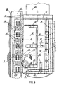
- FIG. 2 shows a top cross section of the elevator column.
- FIG. 3 shows a side view of the elevator with crane on a transport vehicle.
- FIG. 4 shows a side view of the elevator with crane being installed on a rail.
- FIG. 5 shows a top view of the elevator with the arms open and wheels disengaged from the rail.
- FIG. 6 shows a top view of the elevator with the arms closed and wheels engaging the rail.
- FIG. 7 is a front cross sectional view of an elevator connected to a trolley.
- FIG. 8 shows a top cross sectional view of an elevator on the H shaped rail.
- FIG. 9 is a side cross sectional view of the elevator with crane on the rail.
- High-rise buildings are hazardous during fires since fire-fighting equipment is limited to reaching only the lower floors because ladders, cherry pickers and other equipment have limits of extension well short of the upper floors.
- a further hazard is that inside elevators cannot be used during a fire since people could become trapped inside the elevators or be exposed to smoke. It therefore becomes difficult to evacuate a high-rise building during a fire, to rescue people trapped inside or to fight the fire.
- the equipment can also be used during construction to haul materials and workmen to the positions on the outside of the building or to access the upper floors and roof during construction.
- the invention provides a vertical column or rail 17 attached to the outside surface of a building 18 and an elevator car or elevator cars 3 and 58 attached to the rail 17 for riding up and down the outside of the building 18 .
- building 18 has a housing 59 on the roof containing lifting mechanism 57 , which comprises motors 151 and 152 for driving two separate spools 251 and 252 respectively, having two separate cables 351 and 352 respectively, for lifting or lowering the elevator cars 3 or 58 .
- lifting mechanism 57 which comprises motors 151 and 152 for driving two separate spools 251 and 252 respectively, having two separate cables 351 and 352 respectively, for lifting or lowering the elevator cars 3 or 58 .
- Elevator 58 is stored in housing 59 until it is needed. It is aligned with emergency exits 69 on the outside of building 18 for evacuating people during emergencies such as a fire.
- Shock absorbing elements 53 at the base of column 17 help provide a smooth stop for elevator car 58 at the base of building 18 .
- An auxiliary power supply 68 can be used to supply power to the motors 151 and 152 to power the elevators 3 and 58 in case of a power outage in the building 18 .
- the power supply 68 plugs into the column 17 at electrical connector 60 .
- the controls for elevators 3 and 58 can be in the elevators or remotely controlled from ground at control station 70 .
- Elevator 3 has a crane portion attached on the top.
- the crane portion comprises a pivoting mechanism 20 , a turning mechanism 21 , a telescoping arm 4 , a pivoting mechanism 22 , and a cabin 5 .
- the cabin 5 can support fire fighting equipment 48 and firemen 101 .
- the cabin 5 can be rotated on turning mechanism 23 .
- the crane portion can position the cabin 5 at any desired position along the face of the building 18 by a combination of the elevator 3 moving up or down, and the crane portion using the pivoting mechanism 20 to swing the telescoping arm 4 to the desired angle and then extending or retracting to a desired position adjacent building 18 .
- the turning mechanism 21 can move the cabin 5 toward or away from the building 18 .
- the cabin 5 can be used to rescue people who cannot get to the emergency exits 69 .
- the vertical column 17 can be attached to a building 18 as the building is being constructed or it can be added to an existing building.
- the vertical column 17 can have expansion joints 103 between sections of r rail 17 .
- the expansion joints 103 are made out of an alloy or material which is fireproof and has a low coefficient of expansion with temperature.
- vertical column or rail 17 has an H shape and has several features designed for use with the elevators 3 , 58 .
- the vertical column 17 has a high friction coating 19 to make a better contact with tires 9 on the elevators 3 and 58 .
- a power cable channel 72 in the H shaped vertical column 17 allows electrical power cables 52 to access the roof to drive motors 151 and 152 .
- Guides 38 on the outside face of vertical column 17 allow for wheels 9 or cog wheels 36 on the elevators 3 and 58 to engage the vertical column 17 and keep the elevators 3 , 58 aligned on the column 17 .
- Lights 56 may also be installed on the vertical column 17 to help during nighttime operations.
- the H shaped vertical column 17 also has a trolley channel 61 for cables 251 and 252 to travel in.
- the trolley cables 251 and 252 are connected to trolleys 45 and 55 , which run separately in trolley channel 61 .
- Trolley 45 is attached to elevator car 3 and trolley 55 is attached to elevator car 58 .
- Trolley wheels 64 engage the trolley guides 62 in the trolley channel 61 .
- the elevator 3 and the crane portion are transportable to building 18 by a truck 1 .
- the elevator 3 is for fire fighting the truck 1 may be a specialized fire truck. If the elevator is used during construction or maintenance the truck may be a construction truck.
- truck 1 arrives at building 18 the elevator 3 is attached to the rail 17 .
- elevator 3 can be removed from the rail 17 and used on another portion of the same building or moved to a different building.
- FIG. 4 shows elevator 3 being installed on vertical column 17 .
- Truck 1 is adjacent the building 18 .
- the top surface 2 of the truck 1 has a rotating mechanism 25 for turning pivoting mechanism 27 which has a telescoping arm 26 attached.
- Telescoping arm 26 is connected to pivoting mechanism 29 , which is connected to holding mechanism 28 for holding elevator 3 in position for connecting it to vertical column 17 .
- FIG. 9 shows how the elevator 3 is lifted into place by holding mechanism 28 .
- Forklift tines 30 are inserted into a portion of the elevator 3 .
- the fork lift tines 30 have apertures 33 which are engaged by jack elements 32 to lock the elevator 3 onto the fork lift tines while the elevator 3 is being positioned by against rail 17 .
- a stabilizing slot 35 on elevator 3 helps hold the elevator 3 in position on holding mechanism 28 , which fits into the slot.
- electromagnets 34 can be used to either hold the elevator in position relative to the holding mechanism 28 or act in conjunction with the fork tines 30 to hold the elevator 3 in place.
- the H shaped column 17 is engaged by elastic tires 9 on wheels 15 , prevent left to right movement on the rail 17 relative to the building 18 .
- the wheels 15 are supported on frames 14 attached to spreadable arms 13 .
- the arms 13 pivot on hinge 12 and are opened or closed by operating pistons 16 .
- When arms 13 are opened the elevator portion 3 can be removed from the H shaped rail 17 .
- the elevator portion 3 is attached to the rail 17 .
- Guides 38 indented in the columns 17 engage wheels such as cogwheels 36 , which engage apertures or racks 76 in the columns 17 to grippingly engage the column 17 .
- a brake having break calipers 39 operating on disc 37 attached to cog wheel 36 can be used by operating brake lever 41 attached to brake cable 40 for stopping the elevator portion 3 in emergencies by pulling on emergency break 41 in cabin 5 on elevator 3 or in elevator 58 .
- elevator 3 With elevator 3 held in place on column 17 it can be connected to trolley 45 by a cable 66 having an eye connector 42 on the end of the cable and placed on hook 43 , which is attached by a cable 65 to the trolley 45 .
- Elevator 58 as shown in FIG. 8 is attached to column 17 in a similar manner as elevator 3 , the difference being that elevator 58 is permanently connected to the column 17 . Therefore wheel frame 14 is permanently in place for holding the tires 9 on wheels 15 against column 17 .
- the cogwheels 36 can be used as the drive wheels.
- An engine compartment 7 in FIG. 9 , has an engine or electric motor for providing power to drive wheels 36 for propelling the elevator portion 3 along column 17 .
- the engine compartment 7 in this embodiment replaces a portion of the storage tank 6 for fire fighting foam in the elevator 3 since cable 45 lifts and lowers the elevator 3 .
- the elevator 58 or cabin 3 can carry passengers.
- the elevators can have fireproof doors 46 and fireproof windows 47 and walls.
- Elevator 58 can be directly connected to trolley 55 without intervening cables since it is permanently connected to rail 17 .
- Cabin 5 has an access hatch 49 for climbing out of the cabin 5 to the top of the cabin which has a flat roof for standing on and a railing 50 .
- Fire fighting equipment 48 such as a nozzle can be used to spray water, foam or chemicals on a fire.
- FIG. 1 shows expansion joint 203 in rail 17 .
Abstract
Description
Claims (8)
Priority Applications (4)
| Application Number | Priority Date | Filing Date | Title |
|---|---|---|---|
| US10/334,023 US7036630B2 (en) | 2002-07-26 | 2002-12-30 | High-rise, fire-fighting, rescue and construction equipment |
| US10/431,946 US7204344B2 (en) | 2002-07-26 | 2003-05-08 | High-rise, fire-fighting, rescue and construction equipment |
| US10/663,260 US7165650B2 (en) | 2002-07-26 | 2003-09-16 | High-rise, fire-fighting, rescue and construction equipment |
| US10/793,508 US7290640B2 (en) | 2002-07-26 | 2004-03-04 | High-rise, fire-fighting, rescue and construction equipment |
Applications Claiming Priority (2)
| Application Number | Priority Date | Filing Date | Title |
|---|---|---|---|
| US10/205,981 US7096996B2 (en) | 2002-07-26 | 2002-07-26 | High-rise fire-fighting, rescue and construction equipment |
| US10/334,023 US7036630B2 (en) | 2002-07-26 | 2002-12-30 | High-rise, fire-fighting, rescue and construction equipment |
Related Parent Applications (1)
| Application Number | Title | Priority Date | Filing Date |
|---|---|---|---|
| US10/205,981 Continuation-In-Part US7096996B2 (en) | 2002-07-26 | 2002-07-26 | High-rise fire-fighting, rescue and construction equipment |
Related Child Applications (2)
| Application Number | Title | Priority Date | Filing Date |
|---|---|---|---|
| US10/431,946 Continuation-In-Part US7204344B2 (en) | 2002-07-26 | 2003-05-08 | High-rise, fire-fighting, rescue and construction equipment |
| US10/793,508 Continuation-In-Part US7290640B2 (en) | 2002-07-26 | 2004-03-04 | High-rise, fire-fighting, rescue and construction equipment |
Publications (2)
| Publication Number | Publication Date |
|---|---|
| US20050023082A1 US20050023082A1 (en) | 2005-02-03 |
| US7036630B2 true US7036630B2 (en) | 2006-05-02 |
Family
ID=46301530
Family Applications (1)
| Application Number | Title | Priority Date | Filing Date |
|---|---|---|---|
| US10/334,023 Expired - Fee Related US7036630B2 (en) | 2002-07-26 | 2002-12-30 | High-rise, fire-fighting, rescue and construction equipment |
Country Status (1)
| Country | Link |
|---|---|
| US (1) | US7036630B2 (en) |
Cited By (3)
| Publication number | Priority date | Publication date | Assignee | Title |
|---|---|---|---|---|
| US20100100244A1 (en) * | 2004-09-30 | 2010-04-22 | Waymon Burton Reed | Reed's High Rise Emergency Rescue Egress System |
| US20100163339A1 (en) * | 2007-06-12 | 2010-07-01 | Han Yong-Seob | Fire escape apparatus for building |
| US11697553B1 (en) | 2020-01-15 | 2023-07-11 | Stanislav Markovich | Multi-story structure package delivery system |
Families Citing this family (10)
| Publication number | Priority date | Publication date | Assignee | Title |
|---|---|---|---|---|
| US7191873B2 (en) * | 2003-10-07 | 2007-03-20 | Pavel V. Korchagin | High-rise fire-fighting, rescue and construction equipment |
| WO2005076738A2 (en) * | 2004-02-18 | 2005-08-25 | Electra Ltd. | Mass rescue and evacuation system |
| FR2894237B1 (en) * | 2005-12-02 | 2009-05-29 | Manuel Machado | NACELLE WITH MOTOR VEHICLE PROPULSION AND SAFETY MECHANISM |
| WO2008047567A1 (en) * | 2006-09-27 | 2008-04-24 | Kyocera Corporation | Solar cell device and method for manufacturing the same |
| US9150397B2 (en) * | 2011-09-27 | 2015-10-06 | Chicago Bridge & Iron Company | Freestanding elevator platform system |
| CN105459125B (en) * | 2015-12-20 | 2017-10-20 | 华南理工大学 | A kind of high-rise rescue robot system and its Quick rescue method based on internet |
| CN107137840A (en) * | 2017-05-20 | 2017-09-08 | 利辛县江淮扬天汽车有限公司 | A kind of semitrailer provided with fire plant |
| CA3039357A1 (en) * | 2018-04-11 | 2019-10-11 | C&E Group S.R.L. | Apparatus for the transport of a device along a construction |
| CN113800390A (en) * | 2020-10-23 | 2021-12-17 | 邓允河 | Fire rescue system |
| CN113911886B (en) * | 2021-12-16 | 2022-04-15 | 河南凌云消防安全技术有限公司 | Fire-fighting and rescue mechanical platform for high-rise building |
Citations (9)
| Publication number | Priority date | Publication date | Assignee | Title |
|---|---|---|---|---|
| US394781A (en) * | 1888-12-18 | Ludwig maurer | ||
| US4023503A (en) * | 1974-10-03 | 1977-05-17 | Tekniska Rontgencentralen Ab | Conveying installation |
| US4406349A (en) * | 1981-05-19 | 1983-09-27 | Andrew Vilchek | Escape apparatus |
| US4499966A (en) * | 1983-02-22 | 1985-02-19 | Tundra Holdings Ltd. | Emergency escape system |
| US4830141A (en) * | 1988-09-01 | 1989-05-16 | Pegasus International, Inc. | Deployable rail structure for high-rise building evacuation system |
| US4865155A (en) * | 1988-07-21 | 1989-09-12 | Pegasus International, Inc. | High-rise fire fighting and rescue system |
| DE3939762A1 (en) * | 1989-12-01 | 1991-06-06 | Boecker Albert Gmbh & Co Kg | Person and material lift for building sites - in which internal power source and drives toothed belt engaging in vertical toothed poles forming guideway |
| US5533670A (en) * | 1995-04-05 | 1996-07-09 | Chen; Chi-Shiang | Rail joint for expansion between rails with inverted T-shaped base holder |
| US20040086333A1 (en) * | 2002-11-06 | 2004-05-06 | Craig Swartz | Illuminated snowboard railway track |
-
2002
- 2002-12-30 US US10/334,023 patent/US7036630B2/en not_active Expired - Fee Related
Patent Citations (9)
| Publication number | Priority date | Publication date | Assignee | Title |
|---|---|---|---|---|
| US394781A (en) * | 1888-12-18 | Ludwig maurer | ||
| US4023503A (en) * | 1974-10-03 | 1977-05-17 | Tekniska Rontgencentralen Ab | Conveying installation |
| US4406349A (en) * | 1981-05-19 | 1983-09-27 | Andrew Vilchek | Escape apparatus |
| US4499966A (en) * | 1983-02-22 | 1985-02-19 | Tundra Holdings Ltd. | Emergency escape system |
| US4865155A (en) * | 1988-07-21 | 1989-09-12 | Pegasus International, Inc. | High-rise fire fighting and rescue system |
| US4830141A (en) * | 1988-09-01 | 1989-05-16 | Pegasus International, Inc. | Deployable rail structure for high-rise building evacuation system |
| DE3939762A1 (en) * | 1989-12-01 | 1991-06-06 | Boecker Albert Gmbh & Co Kg | Person and material lift for building sites - in which internal power source and drives toothed belt engaging in vertical toothed poles forming guideway |
| US5533670A (en) * | 1995-04-05 | 1996-07-09 | Chen; Chi-Shiang | Rail joint for expansion between rails with inverted T-shaped base holder |
| US20040086333A1 (en) * | 2002-11-06 | 2004-05-06 | Craig Swartz | Illuminated snowboard railway track |
Cited By (3)
| Publication number | Priority date | Publication date | Assignee | Title |
|---|---|---|---|---|
| US20100100244A1 (en) * | 2004-09-30 | 2010-04-22 | Waymon Burton Reed | Reed's High Rise Emergency Rescue Egress System |
| US20100163339A1 (en) * | 2007-06-12 | 2010-07-01 | Han Yong-Seob | Fire escape apparatus for building |
| US11697553B1 (en) | 2020-01-15 | 2023-07-11 | Stanislav Markovich | Multi-story structure package delivery system |
Also Published As
| Publication number | Publication date |
|---|---|
| US20050023082A1 (en) | 2005-02-03 |
Similar Documents
| Publication | Publication Date | Title |
|---|---|---|
| US7597175B2 (en) | Reed's high-rise emergency rescue egress system | |
| US7036630B2 (en) | High-rise, fire-fighting, rescue and construction equipment | |
| US4469198A (en) | Outside rescue elevator system for high-rise buildings | |
| US4018306A (en) | Emergency building access apparatus | |
| US7165650B2 (en) | High-rise, fire-fighting, rescue and construction equipment | |
| US7191873B2 (en) | High-rise fire-fighting, rescue and construction equipment | |
| US7204344B2 (en) | High-rise, fire-fighting, rescue and construction equipment | |
| US8833522B2 (en) | Method and apparatus for reaching from outside an upper level of a tall structure | |
| US20070119331A1 (en) | Lifting systems for high-rise buildings | |
| US4042066A (en) | Portable emergency fire fighting and rescue elevator | |
| EP1725489B1 (en) | High-rise fire fighting, rescue and construction equipement | |
| WO1999021788A1 (en) | Outside rescue elevator system | |
| US20150136525A1 (en) | Method and apparatus for reaching from outside an upper level of a tall structure | |
| US7096996B2 (en) | High-rise fire-fighting, rescue and construction equipment | |
| GB2435641A (en) | High-rise fire fighting, rescue and construction equipment | |
| KR101374540B1 (en) | Aerial ladder truck | |
| GB2435642A (en) | High-rise fire fighting, rescue and construction equipment | |
| EA008405B1 (en) | An elevator system, a rail therefor, a method for accessing the face of a building | |
| RU2656204C1 (en) | Rescue system for altitude buildings | |
| KR950008916Y1 (en) | A rescue equipment for man | |
| JP2525119Y2 (en) | High-rise building wall lifting device | |
| IT202100015215A1 (en) | Emergency lift system for skyscrapers that runs vertically and translates horizontally, or sub-vertically, always remaining parallel to the facade of the building | |
| MXPA00004140A (en) | Outside rescue elevator system |
Legal Events
| Date | Code | Title | Description |
|---|---|---|---|
| AS | Assignment |
Owner name: KORCHAGIN, PAVEL V., RUSSIAN FEDERATION Free format text: ASSIGNMENT OF ASSIGNORS INTEREST;ASSIGNORS:KORCHAGIN, PAVEL V.;KORCHAGINA, MARINA E.;YUDAKOV, VLADIMIR I.;AND OTHERS;REEL/FRAME:016770/0148 Effective date: 20050707 Owner name: KORCHAGINA, MARINA E., RUSSIAN FEDERATION Free format text: ASSIGNMENT OF ASSIGNORS INTEREST;ASSIGNORS:KORCHAGIN, PAVEL V.;KORCHAGINA, MARINA E.;YUDAKOV, VLADIMIR I.;AND OTHERS;REEL/FRAME:016770/0148 Effective date: 20050707 Owner name: YUDAKOV, VLADIMIR I., RUSSIAN FEDERATION Free format text: ASSIGNMENT OF ASSIGNORS INTEREST;ASSIGNORS:KORCHAGIN, PAVEL V.;KORCHAGINA, MARINA E.;YUDAKOV, VLADIMIR I.;AND OTHERS;REEL/FRAME:016770/0148 Effective date: 20050707 Owner name: TIRSKIY, ANDREY G., RUSSIAN FEDERATION Free format text: ASSIGNMENT OF ASSIGNORS INTEREST;ASSIGNORS:KORCHAGIN, PAVEL V.;KORCHAGINA, MARINA E.;YUDAKOV, VLADIMIR I.;AND OTHERS;REEL/FRAME:016770/0148 Effective date: 20050707 Owner name: GOLDSTEIN, IGOR I., MINNESOTA Free format text: ASSIGNMENT OF ASSIGNORS INTEREST;ASSIGNORS:KORCHAGIN, PAVEL V.;KORCHAGINA, MARINA E.;YUDAKOV, VLADIMIR I.;AND OTHERS;REEL/FRAME:016770/0148 Effective date: 20050707 |
|
| FEPP | Fee payment procedure |
Free format text: PAYOR NUMBER ASSIGNED (ORIGINAL EVENT CODE: ASPN); ENTITY STATUS OF PATENT OWNER: SMALL ENTITY |
|
| FPAY | Fee payment |
Year of fee payment: 4 |
|
| REMI | Maintenance fee reminder mailed | ||
| LAPS | Lapse for failure to pay maintenance fees | ||
| STCH | Information on status: patent discontinuation |
Free format text: PATENT EXPIRED DUE TO NONPAYMENT OF MAINTENANCE FEES UNDER 37 CFR 1.362 |
|
| FP | Lapsed due to failure to pay maintenance fee |
Effective date: 20140502 |