US7028889B2 - Media cassette and media dispenser having the same - Google Patents
Media cassette and media dispenser having the same Download PDFInfo
- Publication number
- US7028889B2 US7028889B2 US10/318,071 US31807102A US7028889B2 US 7028889 B2 US7028889 B2 US 7028889B2 US 31807102 A US31807102 A US 31807102A US 7028889 B2 US7028889 B2 US 7028889B2
- Authority
- US
- United States
- Prior art keywords
- media
- casing
- mounting portion
- slot
- discharging
- Prior art date
- Legal status (The legal status is an assumption and is not a legal conclusion. Google has not performed a legal analysis and makes no representation as to the accuracy of the status listed.)
- Expired - Lifetime
Links
- 238000007599 discharging Methods 0.000 claims abstract description 40
- 238000010276 construction Methods 0.000 description 6
- 230000004048 modification Effects 0.000 description 1
- 238000012986 modification Methods 0.000 description 1
Images


Classifications
-
- G—PHYSICS
- G07—CHECKING-DEVICES
- G07F—COIN-FREED OR LIKE APPARATUS
- G07F19/00—Complete banking systems; Coded card-freed arrangements adapted for dispensing or receiving monies or the like and posting such transactions to existing accounts, e.g. automatic teller machines
-
- B—PERFORMING OPERATIONS; TRANSPORTING
- B65—CONVEYING; PACKING; STORING; HANDLING THIN OR FILAMENTARY MATERIAL
- B65H—HANDLING THIN OR FILAMENTARY MATERIAL, e.g. SHEETS, WEBS, CABLES
- B65H1/00—Supports or magazines for piles from which articles are to be separated
-
- G—PHYSICS
- G07—CHECKING-DEVICES
- G07D—HANDLING OF COINS OR VALUABLE PAPERS, e.g. TESTING, SORTING BY DENOMINATIONS, COUNTING, DISPENSING, CHANGING OR DEPOSITING
- G07D11/00—Devices accepting coins; Devices accepting, dispensing, sorting or counting valuable papers
- G07D11/10—Mechanical details
- G07D11/12—Containers for valuable papers
- G07D11/125—Secure containers
-
- G—PHYSICS
- G07—CHECKING-DEVICES
- G07D—HANDLING OF COINS OR VALUABLE PAPERS, e.g. TESTING, SORTING BY DENOMINATIONS, COUNTING, DISPENSING, CHANGING OR DEPOSITING
- G07D11/00—Devices accepting coins; Devices accepting, dispensing, sorting or counting valuable papers
- G07D11/10—Mechanical details
- G07D11/12—Containers for valuable papers
- G07D11/13—Containers for valuable papers with internal means for handling valuable papers
-
- B—PERFORMING OPERATIONS; TRANSPORTING
- B65—CONVEYING; PACKING; STORING; HANDLING THIN OR FILAMENTARY MATERIAL
- B65H—HANDLING THIN OR FILAMENTARY MATERIAL, e.g. SHEETS, WEBS, CABLES
- B65H2405/00—Parts for holding the handled material
- B65H2405/30—Other features of supports for sheets
- B65H2405/31—Supports for sheets fully removable from the handling machine, e.g. cassette
-
- B—PERFORMING OPERATIONS; TRANSPORTING
- B65—CONVEYING; PACKING; STORING; HANDLING THIN OR FILAMENTARY MATERIAL
- B65H—HANDLING THIN OR FILAMENTARY MATERIAL, e.g. SHEETS, WEBS, CABLES
- B65H2407/00—Means not provided for in groups B65H2220/00 – B65H2406/00 specially adapted for particular purposes
- B65H2407/30—Means for preventing damage of handled material, e.g. by controlling atmosphere
-
- B—PERFORMING OPERATIONS; TRANSPORTING
- B65—CONVEYING; PACKING; STORING; HANDLING THIN OR FILAMENTARY MATERIAL
- B65H—HANDLING THIN OR FILAMENTARY MATERIAL, e.g. SHEETS, WEBS, CABLES
- B65H2701/00—Handled material; Storage means
- B65H2701/10—Handled articles or webs
- B65H2701/19—Specific article or web
- B65H2701/1912—Banknotes, bills and cheques or the like
Definitions
- the present invention relates to a media cassette and a media dispenser having the same.
- An automatic teller machine (ATM) or a cash dispenser (CD) installed at a bank or a convenient store are devices for dispensing cash by a user's simple. handling.
- the ATM has a media cassette in which media such as a bank note are stacked. Cash is dispensed outside by a transport unit through a discharging slot formed in the media cassette.
- the media cassette is empty, the media cassette will be replaced by another media cassette where media are stacked.
- the conventional media cassette has a problem that media are left out through the discharging slot by their weight when the media cassette is transported with the media stacked therein.
- the media left out from a media cassette have to be stacked in the media cassette again, thereby having a complicated problem.
- an object of the present invention is to provide a media cassette for opening a discharging slot thereof when the media cassette is mounted on a media dispenser and shielding the discharging slot when the media cassette is detached from the media dispenser and a media dispenser having the same.
- a media cassette comprising: a casing mounted on a mounting portion of a media dispenser and having a stack space in which media are stacked; a discharging slot formed in the casing for discharging the media stacked in the stack space out of the casing in an edge direction of the media; and a slot shielding unit for opening the discharging slot when the casing is mounted on the mounting portion and shielding the discharging slot when the casing is detached from the mounting portion.
- a media dispenser comprising: a mounting portion; a casing mounted on the mounting portion and having a stack space where media are stacked; a discharging slot formed in the casing for discharging the media stacked in the stack space out of the casing in an edge direction of the media; and a slot shielding unit for opening the discharging slot when the casing is mounted on the mounting portion and shielding the discharging slot when the casing is detached from the mounting portion.
- FIG. 1 is a lateral view of a media cassette according to the first embodiment of the present invention
- FIG. 2 is a sectional view showing an aspect before the media cassette of FIG. 1 is mounted on a media dispenser;
- FIG. 3 is a sectional view showing an aspect after the media cassette of FIG. 1 is mounted on the media dispenser;
- FIG. 4 is a lateral view of a media cassette according to the second preferred embodiment of the present invention.
- FIG. 5 is a sectional view showing an aspect before the media cassette of FIG. 4 is mounted on a mounting portion;
- FIG. 6 is a sectional view showing an aspect after the media cassette of FIG. 4 is mounted on the mounting portion.
- FIG. 7 is a construction view showing a construction of a slot shielding unit of the media cassette of FIG. 4 .
- FIG. 1 is a lateral view of a media cassette according to the first embodiment of the present invention
- FIG. 2 is a sectional view showing an aspect before the media cassette of FIG. 1 is mounted on a media dispenser
- FIG. 3 is a sectional view showing an aspect after the media cassette of FIG. 1 is mounted on the media dispenser.
- the media cassette according to the first embodiment of the present invention comprises: a casing 30 mounted on a mounting portion 20 of a media dispenser and having a stack space S in which media (M) are stacked; a discharging slot 40 formed in the casing 30 for discharging the media stacked in the stack space S out of the casing 30 in an edge direction of the media; and a slot shielding unit 100 for opening the discharging slot 40 when the casing 30 is mounted on the mounting portion 20 and shielding the discharging slot 40 when the casing 30 is detached from the mounting portion 20 .
- the media dispenser 10 such as an automatic teller machine, etc. is a device for dispensing media outside from the media cassette where media such as a thin paper are stacked in an edge direction thereof.
- the casing 30 includes an pushing plate 36 for pushing the media stacked in the stack space S, and an elastic member 37 for adding elasticity force to the pushing plate 36 .
- the pushing plate 36 is connected to a pair of rollers 39 guided by a pair of slots 38 formed at both lateral surfaces of the casing 30 .
- a slot (not shown) for contacting to a transport unit (not shown) installed at the mounting portion 20 of the media dispenser 10 is formed at a frontal surface 34 of the casing 30 .
- a step portion 41 can be formed at a bottom surface 31 of the casing 30 so that the media can have a predetermined interval with the bottom surface 31 of the casing 30 .
- the slot shielding unit 100 includes: a shielding member 110 installed at an upper portion of the bottom surface 31 of the casing 30 where the discharging slot 40 is formed and having an area identical or larger than that of the discharging slot 40 ; an operating member 120 installed on the mounting portion 20 for opening the discharging slot 40 by moving the shielding member 110 when the casing 30 is mounted on the mounting portion 20 ; and a restoring member 130 for restoring the shielding member 110 to an initial position when the casing 30 is detached from the mounting portion 20 .
- the slot shielding unit 100 can be installed below the bottom surface 31 of the casing 30 .
- Both end portions 111 of the shielding member 110 are installed at the casing 30 by a guide portion 112 so as to be linearly movable. Especially, a movement preventing protrusion 113 for preventing the shielding member 110 from moving out of the casing 30 is formed at an upper surface of the shielding member 110 .
- the guide portion 112 fixed to a lateral surface 32 or a bottom surface 31 of the casing 30 is formed as a slot at the bottom surface 31 of the casing so that the shielding member 110 can be linearly movable. Also, the guide portion 112 can be formed as a slot at the lateral surface 32 of the casing 30 .
- the operating member 120 is protruded at the mounting portion 20 corresponding to the frontal surface 34 of the casing 30 .
- a receiving portion 121 for receiving the operating member 120 is formed at the frontal surface 34 of the casing 30 , the operating member 120 is inserted into the receiving portion 121 , and opens the discharging slot 40 by moving both end portions 111 of the shielding member 110 .
- the receiving portion 121 can be formed at both end portions of the frontal surface 34 of the casing 30 .
- the restoring member 130 for restoring the shielding member 110 to an initial position is formed by a coil spring or a plate spring in the first embodiment of the present invention.
- the restoring member 130 is fixed on the bottom surface 31 opposite to the frontal surface 34 on the basis of the shielding member 110 by a fixation member 131 formed at the bottom surface 31 of the casing 30 .
- the guide portion 112 can be fixed to an upper surface of the fixation member 131 .
- the media stacked in the casing 30 are not left out by their weight before mounted on the mounting portion 20 of the media dispenser 10 because the discharging slot 40 is shielded by the shielding member 110 .
- the operating member 120 installed at the mounting portion 20 is inserted into the receiving portion 121 and pushes said both end portions 111 of the shielding member 110 , thereby opening the discharging slot 40 as shown in FIG. 3 .
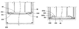
- FIG. 4 is a lateral view of a media cassette according to the second preferred embodiment of the present invention
- FIG. 5 is a sectional view showing an aspect before the media cassette of FIG. 4 is mounted on a mounting portion
- FIG. 6 is a sectional view showing an aspect after the media cassette of FIG. 4 is mounted on the mounting portion
- FIG. 7 is a construction view showing a construction of a slot shielding unit of the media cassette of FIG. 4 .
- a construction of the media cassette according to the second embodiment of the present invention is similar to that of the first embodiment except a construction of the slot shielding portion, thereby omitting its explanation.
- the shielding member 210 of the slot shielding unit 200 is constructed as a pair, and an end portion thereof is fixed to a rotary shaft 211 rotatably installed at the bottom surface 31 of the casing 30 near both ends of the discharging slot 40 .
- an interacting member 240 for opening the discharging slot 40 by interacting with the operating member 220 and rotating the rotary shaft 211 is connected to the rotary shaft 211 .
- the restoring member 230 such as a torsion spring is constructed inserted to the rotary shaft 211 .
- the interacting member 240 is protruded out of the lateral surface 32 of the casing 30 through a through hole 241 formed at the lateral surface 32 of the casing 30 .
- the operating member 220 is constructed as a pair of magnets protruded towards each side of the frontal surface 34 of the casing 30 when the casing 30 is engaged to the mounting portion 20 corresponding to the frontal surface 34 of the casing 30 .
- the shielding member 210 includes an end portion 210 a having a width identical or larger than that of the discharging slot 40 , and a middle portion 210 b concavely cut between the end portion 210 a and the rotary shaft 211 .
- a movement preventing protrusion 213 for preventing the media from moving out of the frontal surface is formed at the upper surface of the shielding member 210 .
- the media stacked in the casing 30 are not left out by their weight before mounted to the mounting portion 20 of the media dispenser 10 because the discharging slot 40 is shielded by the shielding member 210 .
- the interacting member 240 is engaged to the magnet, that is, the operating member 220 installed at the mounting portion 20 , by magnetic force, thereby rotating the rotary shaft 211 .
- the shielding member 210 is rotated, thereby opening the discharging slot 40 .
- media stacked in the media cassette is dispensed through the discharging slot by a transport unit with its operation.
- the media cassette according to the present invention is provided with the slot shielding unit which is opened only when mounted on the media dispenser, so that the media stacked therein are not left out in a state that the media cassette is detached from the media dispenser.
Landscapes
- Physics & Mathematics (AREA)
- General Physics & Mathematics (AREA)
- Engineering & Computer Science (AREA)
- Mechanical Engineering (AREA)
- Business, Economics & Management (AREA)
- Accounting & Taxation (AREA)
- Finance (AREA)
- Sheets, Magazines, And Separation Thereof (AREA)
Abstract
Description
Claims (2)
Applications Claiming Priority (2)
| Application Number | Priority Date | Filing Date | Title |
|---|---|---|---|
| KR1020010079031A KR100746920B1 (en) | 2001-12-13 | 2001-12-13 | Cash dispenser prevention device of cash dispenser |
| KR79031/2001 | 2001-12-13 |
Publications (2)
| Publication Number | Publication Date |
|---|---|
| US20030111789A1 US20030111789A1 (en) | 2003-06-19 |
| US7028889B2 true US7028889B2 (en) | 2006-04-18 |
Family
ID=19717013
Family Applications (1)
| Application Number | Title | Priority Date | Filing Date |
|---|---|---|---|
| US10/318,071 Expired - Lifetime US7028889B2 (en) | 2001-12-13 | 2002-12-13 | Media cassette and media dispenser having the same |
Country Status (2)
| Country | Link |
|---|---|
| US (1) | US7028889B2 (en) |
| KR (1) | KR100746920B1 (en) |
Cited By (1)
| Publication number | Priority date | Publication date | Assignee | Title |
|---|---|---|---|---|
| US20100156034A1 (en) * | 2008-12-18 | 2010-06-24 | Deas Scott H | Media cassette |
Families Citing this family (2)
| Publication number | Priority date | Publication date | Assignee | Title |
|---|---|---|---|---|
| KR100627557B1 (en) * | 2004-12-24 | 2006-09-21 | 노틸러스효성 주식회사 | Banknote Machine Cassette |
| KR100613834B1 (en) * | 2005-12-20 | 2006-08-22 | 송병욱 | Banknote Storage Device for Automatic Cash Payment |
Citations (14)
| Publication number | Priority date | Publication date | Assignee | Title |
|---|---|---|---|---|
| US4275667A (en) * | 1978-12-08 | 1981-06-30 | De La Rue Systems Limited | Sheet counting apparatus |
| US4370006A (en) * | 1980-10-03 | 1983-01-25 | Diebold Incorporated | Banking media security mechanism for automatic banking machines |
| US4438704A (en) * | 1980-07-14 | 1984-03-27 | Ncr Corporation | Cassette for currency notes or other valuable articles |
| US4529118A (en) * | 1983-08-12 | 1985-07-16 | Ncr Corporation | Tampering-proof cassette for receiving currency deposits and identification cards |
| JPS60244720A (en) * | 1984-05-19 | 1985-12-04 | Omron Tateisi Electronics Co | Paper storing equipment |
| US4580422A (en) * | 1983-03-16 | 1986-04-08 | Burroughs Corporation | Replaceable banknote cassette for an autoteller |
| US4593895A (en) * | 1984-04-06 | 1986-06-10 | Ncr Corporation | Automatically adjusting currency pusher plate apparatus |
| US4659008A (en) * | 1985-04-12 | 1987-04-21 | Ncr Corporation | Tampering-proof cassette used in a cash dispenser |
| US4704061A (en) * | 1985-11-12 | 1987-11-03 | Ncr Corporation | Container and method for loading currency notes into a currency cassette |
| US4816652A (en) * | 1987-09-22 | 1989-03-28 | Ncr Corporation | Currency cassette and cash dispensing system including such cassette |
| JPH06295380A (en) * | 1993-04-08 | 1994-10-21 | Fuji Electric Co Ltd | Water-proof cover supporting structure for automatic vending machine |
| JPH08282863A (en) * | 1995-04-12 | 1996-10-29 | Hitachi Ltd | Box-shaped actuator |
| JP2000306139A (en) * | 1999-04-16 | 2000-11-02 | Fuji Electric Co Ltd | Paper storage |
| US6786354B2 (en) * | 2001-10-17 | 2004-09-07 | Ncr Corporation | Media cassette |
Family Cites Families (4)
| Publication number | Priority date | Publication date | Assignee | Title |
|---|---|---|---|---|
| JPH06325241A (en) * | 1993-05-11 | 1994-11-25 | Nippon Conlux Co Ltd | Paper money processor |
| JP3366450B2 (en) * | 1994-07-18 | 2003-01-14 | ローレルバンクマシン株式会社 | Protector for cassette connection part of banknote pay-in / pay-out machine |
| KR200240966Y1 (en) * | 1996-04-08 | 2001-11-22 | 구자홍 | Cash Dispenser for Cash Dispenser |
| JP2000020787A (en) * | 1998-06-29 | 2000-01-21 | Fuji Electric Co Ltd | Paper storage |
-
2001
- 2001-12-13 KR KR1020010079031A patent/KR100746920B1/en not_active Expired - Fee Related
-
2002
- 2002-12-13 US US10/318,071 patent/US7028889B2/en not_active Expired - Lifetime
Patent Citations (15)
| Publication number | Priority date | Publication date | Assignee | Title |
|---|---|---|---|---|
| US4275667A (en) * | 1978-12-08 | 1981-06-30 | De La Rue Systems Limited | Sheet counting apparatus |
| US4438704A (en) * | 1980-07-14 | 1984-03-27 | Ncr Corporation | Cassette for currency notes or other valuable articles |
| US4370006A (en) * | 1980-10-03 | 1983-01-25 | Diebold Incorporated | Banking media security mechanism for automatic banking machines |
| US4580422A (en) * | 1983-03-16 | 1986-04-08 | Burroughs Corporation | Replaceable banknote cassette for an autoteller |
| US4529118A (en) * | 1983-08-12 | 1985-07-16 | Ncr Corporation | Tampering-proof cassette for receiving currency deposits and identification cards |
| US4593895A (en) * | 1984-04-06 | 1986-06-10 | Ncr Corporation | Automatically adjusting currency pusher plate apparatus |
| JPS60244720A (en) * | 1984-05-19 | 1985-12-04 | Omron Tateisi Electronics Co | Paper storing equipment |
| US4638746A (en) * | 1984-05-19 | 1987-01-27 | Omron Tateisi Electronics Co. | Device for automatically opening and closing cash container |
| US4659008A (en) * | 1985-04-12 | 1987-04-21 | Ncr Corporation | Tampering-proof cassette used in a cash dispenser |
| US4704061A (en) * | 1985-11-12 | 1987-11-03 | Ncr Corporation | Container and method for loading currency notes into a currency cassette |
| US4816652A (en) * | 1987-09-22 | 1989-03-28 | Ncr Corporation | Currency cassette and cash dispensing system including such cassette |
| JPH06295380A (en) * | 1993-04-08 | 1994-10-21 | Fuji Electric Co Ltd | Water-proof cover supporting structure for automatic vending machine |
| JPH08282863A (en) * | 1995-04-12 | 1996-10-29 | Hitachi Ltd | Box-shaped actuator |
| JP2000306139A (en) * | 1999-04-16 | 2000-11-02 | Fuji Electric Co Ltd | Paper storage |
| US6786354B2 (en) * | 2001-10-17 | 2004-09-07 | Ncr Corporation | Media cassette |
Non-Patent Citations (1)
| Title |
|---|
| Pop-Up Cash Box, Mar. 1, 1984, IBM Technical Disclosure Bulletin, Issue 10B, vol. 26, pp. 5773-5774. * |
Cited By (2)
| Publication number | Priority date | Publication date | Assignee | Title |
|---|---|---|---|---|
| US20100156034A1 (en) * | 2008-12-18 | 2010-06-24 | Deas Scott H | Media cassette |
| US8196920B2 (en) * | 2008-12-18 | 2012-06-12 | Ncr Corporation | Media cassette |
Also Published As
| Publication number | Publication date |
|---|---|
| US20030111789A1 (en) | 2003-06-19 |
| KR100746920B1 (en) | 2007-08-08 |
| KR20030048972A (en) | 2003-06-25 |
Similar Documents
| Publication | Publication Date | Title |
|---|---|---|
| US8998206B2 (en) | Medium feeding direction switching mechanism and medium issuing and collecting device | |
| EP1465123B1 (en) | Currency cassette pressure plate assembly | |
| US7028889B2 (en) | Media cassette and media dispenser having the same | |
| CN110246263A (en) | A kind of channel switching mechanism and two storehouse paper money deposit and withdrawal casees | |
| US20250375010A1 (en) | Card holder | |
| US7497436B2 (en) | Media cassette pusher plate locking mechanism | |
| KR20150079141A (en) | Apparatus for locking cover of cassette | |
| US8540143B2 (en) | Cassette for automated teller machine | |
| US8196920B2 (en) | Media cassette | |
| CN209993029U (en) | Channel switching mechanism and two-bin paper money storing and taking box | |
| CN210836309U (en) | Sheet-like medium storage device and depositing and dispensing machine | |
| KR200390960Y1 (en) | Device of shock-absorbing for cassette frame | |
| JPH06139430A (en) | Paper money identifying/storing device | |
| RU2845346C2 (en) | Device for connection of cassette for atm | |
| KR20060117403A (en) | Cassette Frame Shock Absorber | |
| JP2001351172A (en) | Cash drawer device | |
| JP7839657B2 (en) | Paper sheet thickness detection device, paper sheet identification device, and paper sheet handling device | |
| JPS5847491Y2 (en) | Simultaneous coin insertion prevention mechanism | |
| JP3868165B2 (en) | Information processing device | |
| KR200287627Y1 (en) | ATM with bars for holding paper money | |
| EP4586225A1 (en) | Cassette connecting device for automatic teller machine | |
| US6724573B2 (en) | Tape cassette with front lid held unlocked by lid lock pin caught in lid recess | |
| CN208954197U (en) | Pick-up portion and finance self-help terminal | |
| JP2503939Y2 (en) | Coil type coin discriminator | |
| KR200389648Y1 (en) | Cash transaction machine of having discriminative cassette construction by kind of paper money |
Legal Events
| Date | Code | Title | Description |
|---|---|---|---|
| AS | Assignment |
Owner name: LG N-SYS INC., KOREA, REPUBLIC OF Free format text: ASSIGNMENT OF ASSIGNORS INTEREST;ASSIGNOR:JUN, DAE-KEUN;REEL/FRAME:013580/0805 Effective date: 20021129 |
|
| FEPP | Fee payment procedure |
Free format text: PAYOR NUMBER ASSIGNED (ORIGINAL EVENT CODE: ASPN); ENTITY STATUS OF PATENT OWNER: LARGE ENTITY |
|
| STCF | Information on status: patent grant |
Free format text: PATENTED CASE |
|
| FPAY | Fee payment |
Year of fee payment: 4 |
|
| FEPP | Fee payment procedure |
Free format text: PAYOR NUMBER ASSIGNED (ORIGINAL EVENT CODE: ASPN); ENTITY STATUS OF PATENT OWNER: LARGE ENTITY Free format text: PAYER NUMBER DE-ASSIGNED (ORIGINAL EVENT CODE: RMPN); ENTITY STATUS OF PATENT OWNER: LARGE ENTITY |
|
| AS | Assignment |
Owner name: LG CNS CO., LTD., KOREA, REPUBLIC OF Free format text: ASSIGNMENT OF ASSIGNORS INTEREST;ASSIGNOR:LG N-SYS INC.;REEL/FRAME:030466/0722 Effective date: 20130513 |
|
| FPAY | Fee payment |
Year of fee payment: 8 |
|
| MAFP | Maintenance fee payment |
Free format text: PAYMENT OF MAINTENANCE FEE, 12TH YEAR, LARGE ENTITY (ORIGINAL EVENT CODE: M1553) Year of fee payment: 12 |
|
| AS | Assignment |
Owner name: ATEC AP CO., LTD., KOREA, REPUBLIC OF Free format text: ASSIGNMENT OF ASSIGNORS INTEREST;ASSIGNOR:LG CNS CO., LTD.;REEL/FRAME:047110/0690 Effective date: 20180424 |