US7028443B2 - Wire mesh chair - Google Patents
Wire mesh chair Download PDFInfo
- Publication number
- US7028443B2 US7028443B2 US10/614,715 US61471503A US7028443B2 US 7028443 B2 US7028443 B2 US 7028443B2 US 61471503 A US61471503 A US 61471503A US 7028443 B2 US7028443 B2 US 7028443B2
- Authority
- US
- United States
- Prior art keywords
- chair
- receiving area
- base
- foot member
- strands
- Prior art date
- Legal status (The legal status is an assumption and is not a legal conclusion. Google has not performed a legal analysis and makes no representation as to the accuracy of the status listed.)
- Expired - Lifetime, expires
Links
- 239000004567 concrete Substances 0.000 claims abstract description 22
- 230000000295 complement effect Effects 0.000 claims abstract description 11
- 239000000463 material Substances 0.000 claims description 13
- -1 polypropylene Polymers 0.000 claims description 5
- 238000003780 insertion Methods 0.000 claims description 4
- 230000037431 insertion Effects 0.000 claims description 4
- 239000004743 Polypropylene Substances 0.000 claims description 3
- 229920001155 polypropylene Polymers 0.000 claims description 3
- 238000002347 injection Methods 0.000 claims description 2
- 239000007924 injection Substances 0.000 claims description 2
- 229910000831 Steel Inorganic materials 0.000 description 6
- 238000010276 construction Methods 0.000 description 6
- 230000002787 reinforcement Effects 0.000 description 6
- 239000010959 steel Substances 0.000 description 6
- 238000000926 separation method Methods 0.000 description 5
- 230000000694 effects Effects 0.000 description 4
- 230000014759 maintenance of location Effects 0.000 description 4
- 238000004806 packaging method and process Methods 0.000 description 4
- 238000000034 method Methods 0.000 description 3
- 230000000717 retained effect Effects 0.000 description 3
- 239000004698 Polyethylene Substances 0.000 description 2
- 238000005260 corrosion Methods 0.000 description 2
- 230000007797 corrosion Effects 0.000 description 2
- 238000004519 manufacturing process Methods 0.000 description 2
- 230000009972 noncorrosive effect Effects 0.000 description 2
- 239000004033 plastic Substances 0.000 description 2
- 229920003023 plastic Polymers 0.000 description 2
- 229920000573 polyethylene Polymers 0.000 description 2
- 230000003014 reinforcing effect Effects 0.000 description 2
- 239000004576 sand Substances 0.000 description 2
- 239000002689 soil Substances 0.000 description 2
- 239000007787 solid Substances 0.000 description 2
- 125000006850 spacer group Chemical group 0.000 description 2
- 230000001747 exhibiting effect Effects 0.000 description 1
- 239000012530 fluid Substances 0.000 description 1
- 238000009434 installation Methods 0.000 description 1
- 239000007788 liquid Substances 0.000 description 1
- 238000012986 modification Methods 0.000 description 1
- 230000004048 modification Effects 0.000 description 1
- 239000011150 reinforced concrete Substances 0.000 description 1
- 239000011347 resin Substances 0.000 description 1
- 229920005989 resin Polymers 0.000 description 1
Images


Classifications
-
- E—FIXED CONSTRUCTIONS
- E04—BUILDING
- E04C—STRUCTURAL ELEMENTS; BUILDING MATERIALS
- E04C5/00—Reinforcing elements, e.g. for concrete; Auxiliary elements therefor
- E04C5/16—Auxiliary parts for reinforcements, e.g. connectors, spacers, stirrups
- E04C5/168—Spacers connecting parts for reinforcements and spacing the reinforcements from the form
-
- E—FIXED CONSTRUCTIONS
- E04—BUILDING
- E04C—STRUCTURAL ELEMENTS; BUILDING MATERIALS
- E04C5/00—Reinforcing elements, e.g. for concrete; Auxiliary elements therefor
- E04C5/16—Auxiliary parts for reinforcements, e.g. connectors, spacers, stirrups
- E04C5/162—Connectors or means for connecting parts for reinforcements
- E04C5/166—Connectors or means for connecting parts for reinforcements the reinforcements running in different directions
-
- E—FIXED CONSTRUCTIONS
- E04—BUILDING
- E04C—STRUCTURAL ELEMENTS; BUILDING MATERIALS
- E04C5/00—Reinforcing elements, e.g. for concrete; Auxiliary elements therefor
- E04C5/16—Auxiliary parts for reinforcements, e.g. connectors, spacers, stirrups
- E04C5/20—Auxiliary parts for reinforcements, e.g. connectors, spacers, stirrups of material other than metal or with only additional metal parts, e.g. concrete or plastics spacers with metal binding wires
Definitions
- the present invention relates generally to chairs and spacers that are used in construction activities for the support of steel reinforcement members, and in particular to stackable chairs that are reliably able to retain welded wire mesh within concrete slabs.
- U.S. Pat. No. 5,729,949 to Hartzheim discloses a readily stackable chair with a hollow-conical body that minimizes the amount of shipping and storage space required. These chairs have support legs with apertures between them to allow concrete to flow into the hollow interior of the chair. A worker can carry many chairs at one time and place numerous chairs at a construction site without repeated trips to a storage area.
- U.S. Pat. No. 4,835,933 to Yung, and U.S. Pat. No. 3,693,310 to Middleton both disclose retention means or clips for use in connecting reinforcing members together.
- U.S. Pat. No. 6,282,860 to Ramirez discloses a non-stackable chair for wire mesh which includes pairs of cup shaped members which engage the bars of the wire mesh and may hold the mesh via a retention means.
- One objective of the present invention is to provide a chair designed specifically to fixedly retain wire mesh. Another objective of the invention is to provide a wire mesh chair that can be stacked within another chair to provide a more efficient method for packaging, storage, shipment and ease of handling and convenience at the job site. It is a further objective of the present invention to provide a wire mesh chair with a wide base that allows the chair to stand securely. It is also an objective to provide a plastic chair made of durable, non-corrosive materials that is easy to manufacture and easy to use with wire mesh.
- a tapered wire mesh chair having a hollow body with a receiving area for fixedly retaining the wire mesh.
- the receiving area has a plurality of notches, walls, and detents which work in a cooperative manner to snap-fit or retain the wire mesh within the receiving area.
- the walls project upwardly between the notches and have generally planar or flat tops which connect to the detents.
- the receiving area secures and retains the intersecting portions of the wire mesh.
- the detents extend horizontally inwardly from the upstanding walls in an off-centered fashion. There is an upper opening in the receiving area that permits a crossing section of the wire mesh to enter the chair. The crossing sections of the wire mesh are retained in the passageways by the off-centered detents, and are inserted through the upper opening and over the detents, fitting into the passageways which are defined by adjacent walls.
- the body of the wire mesh chair may have multiple substantially straight sides and a substantially square cross-section having rounded corners, with an inner surface that is complementary to the outer surface to allow a plurality of chairs to be stacked together, one inside the other, for storage and shipment.
- the chair may also have an elliptical, oval or hybrid cross-section.
- the chair preferably has a wide base which is adapted to rest on a flat support surface.
- the upper opening is defined by the receiving area and a lower opening is defined by the base.
- the lower opening is preferably larger than the upper opening, and the inner and outer surfaces are preferably substantially complementary to each other.
- the base has a plurality of separate support legs extending downwardly from the receiving area. Adjacent support legs define apertures or holes between them, which allow poured concrete to pass fluidly through the chair.
- One or more supporting foot members are preferably attached to the lower base portion to provide for secure support of the chair on a variety of surfaces, including harder surfaces such as a concrete mold or softer surfaces such as graded soil.
- the foot member extends horizontally outwardly from each of the legs, and is preferably a singular flattened, disc-like platform that interconnects the legs, forming a solid band of material around the lower opening.
- each of the legs can be attached to an outwardly extending foot member, such that there are as many foot members as there are legs.
- the foot members are thin protrusions which extend downwardly from the legs and have a projection extending outwardly therefrom, thereby causing a small, narrow footprint. This embodiment is useful for construction of wire mesh-reinforced tilt-up panels.
- the receiving area and the base are integrally formed together from a durable, non-corrosive polymeric material.
- the chairs are easy to manufacture in this fashion, and packaging and storage of the chairs can be done quickly and easily because the chairs are also stackable.
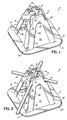
- FIG. 1 is a perspective view of one embodiment of the chair of the present invention
- FIG. 2 is a perspective view of the chair of FIG. 1 in which a wire mesh structure has been placed in the receiving area;
- FIG. 3 is a perspective view of a plurality of chairs stacked within one another in accordance with one aspect of the invention.
- FIG. 4 is a perspective view of another embodiment of the chair of the present invention having individual foot members for each support leg;
- FIG. 5 is a perspective view of a plurality of chairs of FIG. 4 , arranged in a stack;
- FIG. 6 is a perspective view of another embodiment of the chair of the present invention having individual foot members which make a small footprint
- FIG. 7 is a perspective view of a plurality of chairs of FIG. 6 , illustrating the chairs in a stacked configuration
- FIG. 8 is a perspective view of yet another embodiment of a chair according to the present invention.
- FIG. 1 a perspective view is shown of one embodiment of the wire mesh chair 8 of the present invention having a hollow body 10 including a base 12 , a receiving area 14 , an inner surface 16 , and an outer surface 18 .
- Receiving area 14 has a plurality of walls 24 with inwardly facing detents 26 . Walls 24 project upwardly between generally rounded notches 28 . Between the notches 28 are passageways 30 defined by the walls 24 .
- the lower base 12 has a plurality of separate support legs 32 extending downwardly from the receiving area 14 .
- a foot member 34 extends horizontally outwardly from legs 32 .
- Adjacent support legs 32 define holes or apertures 36 , which allow poured concrete to fluidly pass through the wire mesh chair 8 .
- At the base of the support legs are projections, one long projection 42 and three short projections 43 .
- the chair of FIG. 1 is preferably generally square in cross-section having rounded corners and is constructed of a single piece of resilient polymeric material.
- alternative embodiments of the chair may have a polygonal, elliptical, oval, or hybrid cross-section.
- the inner surface 16 is complementary to the outer surface 18
- the body 10 has multiple straight sides and is generally tapered, with the lower opening 22 being larger than the upper opening 20 , thereby allowing multiple chairs to be stacked within one another.
- the tapered shape of the chair also requires that the upper portion of the body 10 , including the receiving area 14 , is generally relatively narrow as compared to the lower portion, which includes the wider base 12 .
- the base 12 includes projections 42 and 43 .
- the projections 42 , 43 are located adjacent legs 32 at generally diagonally opposite positions of foot member 12 . In these locations, projections 42 , 43 help to strengthen the foot member 34 , and thereby provide added strength with minimal increase in materials.
- the projections may alternatively be formed in other locations on the foot member 34 .
- Projection 42 is longer than projections 43 , such that it extends from the base of its support leg 32 to the periphery of its foot member 34 .
- Having one long projection 42 also provides directionality to the chairs, which are preferably square in cross-section. In this way, the chairs can be stacked with the long projection 42 of one chair directly over the long projection 42 of another chair, such that a user can recognize a specific corner of the chair.
- FIG. 2 shows wire mesh strands 38 and 39 being supported by the chair 8 of FIG. 1 .
- Wire mesh strands 38 and 39 intersect and form a junction 40 with one another within the middle part receiving area 14 , and this junction is preferably a welded wire mesh junction.
- Strands 38 and 39 are fixed or retained within the chair by a cooperative relationship between the notches 28 , walls 24 , and detents 26 .
- Detents 26 are preferably resilient to allow the wire mesh strands to pass easily into the passageways 30 .
- Detents 26 project or extend horizontally inwardly from the walls 24 and are designed to fixedly retain the wire mesh strands 38 and 39 in position within the passageways 30 .
- the detents 26 are preferably placed in an off-centered position as they project from the walls 24 , and most preferably project from the upper right side of the walls 24 , as shown in FIG. 2 . Further, each detent can be sloped in a direction toward the base to facilitate insertion of strands into the receiving area.
- the junction 40 of the wire mesh strands 38 , 39 is initially positioned over the upper opening 20 and then snapped or pushed over the off-centered detents 26 .
- the strands 38 , 39 then pass into the passageways 30 between the walls 24 , and the lower strand 38 rests in the notches 28 .
- Notches 28 are curved in a semicircular fashion to receive and support the wire mesh.
- the chair 8 thus supports the adjoined strands 38 and 39 within the passageways 30 at four points an equal distance from the junction 40 of the strands.
- wire mesh strand 38 sits below wire mesh strand 39 within notches 28 .
- Each wire mesh strand 38 , 39 fits within a passageway 30 defined by the walls 24 .
- Detents 26 project or extend horizontally inwardly from walls 24 to secure or otherwise fixedly retain top wire mesh strand 39 in proper position, while bottom wire mesh strand 38 sits within notches 28 and is fixedly retained in this position by walls 24 , as well as by the junction 40 with wire mesh strand 39 .
- FIG. 2 further illustrates the tapered shape of the chair 8 .
- the upper portion of body 10 is narrow at the upper opening 20 between the detents 26 .
- Body 10 gradually widens from the walls 24 down to the foot member 34 .
- Lower opening 22 is much larger than the upper opening 20 , with the upper opening 20 being the geographical center of the wire mesh chair 8 , and each support leg 32 proceeding in a straight line from beneath a notch 28 to a foot member 34 .
- the disc-like foot member 34 extends horizontally outwardly from the support legs 32 , forming a wide base adapted to support the weight of the chair 8 as well as the wire mesh structure.
- the wide base feature improves the stability of the chair, preventing it from tilting and falling.
- the wide base keeps the chair straight up during concrete pouring when the liquid concrete will be coming in from the sides of the chair. Tilting and falling has been observed in chairs with smaller, narrower bases, as the concrete, coming in from the sides of the chairs, pushes and lifts the chairs from the ground. Apertures 36 between the support legs 32 allow fluid concrete to pass through the body 10 beneath the level of wire mesh strands 38 , 39 .
- there is no interconnection of the support legs such that there are as many foot members as there are legs.
- the foot members do not interconnect the legs in a disc-like fashion, they still allow body to be free-standing while supporting a substantial weight on soft grade surfaces. This embodiment is ideal for placement of the chair on a soft grade platform or surface where there is some unevenness of the surface.
- Apertures 36 are shown in FIGS. 1 through 3 as being generally triangular in shape and curved at the apex.
- Support legs 32 are generally of sufficient width and strength to support a substantial load, such as the force of the wire mesh strands 38 and 39 as well as the force applied by construction workers who may step or walk on the wire mesh structure during the construction process.
- the foot member 34 is manufactured as a singular, flattened, disc-like platform that interconnects the legs 32 , forming a solid band of material. around lower opening 22 .
- Foot member 34 allows the base 12 to rest on a flat, planar support surface, including loose or pliant surfaces such as dirt, sand, or the like, without sinking under the weight of the wire mesh strands.
- the detents 26 are shown above the wire mesh strands 38 and 39 , and each detent 26 projects right of the center of its corresponding wall 24 .
- each detent 26 serves to substantially cover the passageway 30 to its right, thereby preventing the strand of wire mesh within that passageway from dislodging.
- Wire mesh strand 38 rests within notches 28
- wire mesh strand 39 rests on top of strand 38 , within passageways 30 , and is secured above by the detents 26 .
- a plurality of chairs can be stacked together, one inside the other, for packaging, storage, shipment and handling at the job site.
- the combination of the tapered, generally funnel-like shape of the body 10 , along with the complementary surfaces 16 , 18 allows the upper receiving area 14 of chair 8 b to be inserted within the lower opening 22 of chair 8 a , such that the outer surface 18 of chair 8 b slidably engages the inner surface 16 of chair 8 a .
- the distance that one chair is able to fit inside a second chair is dependant upon the degree of slope assumed by the surfaces 16 and 18 as the body 10 progresses from the upper opening 20 to the lower opening 22 .
- this slope is sufficient to allow a substantial portion of the first chair to fit within the second chair, such that a great number of chairs can be stacked in a minimal amount of space without the stack becoming too tall or burdensome.
- the stacking ability of the chairs allows a worker to carry a stack of chairs with him in one hand when installing the chairs, which results in substantial savings in time by eliminating multiple trips to and from the supply of chairs at the job site.
- chairs 8 a and 8 b further include a plurality of projections 42 , 43 extending upwardly from the foot member 34 in a direction generally toward the receiving portion 14 .
- the projections 42 , 43 help to maintain a separation between the chairs when they are stacked together, so that individual chairs can be readily separated when desired.
- Projections 42 and 43 also permit the chairs to be stacked together after being formed and while the chairs are still hot, whereby the separation prevents confronting inner and outer surfaces 16 , 18 from sticking together.
- the projections may extend across the entire width of foot member 34 as depicted by projection 42 , or may extend only part way across the width of foot member 34 as illustrated by projection 43 , thereby providing some directionality to the chairs.
- FIG. 4 is an illustration of another exemplary chair 108 of the present invention wherein each of the support legs 132 has a foot member 134 extending radially outwardly therefrom in a horizontal plane.
- there is no interconnection of the support legs 132 such that there are as many foot members 134 as there are legs 132 .
- the foot members 134 do not interconnect the support legs 132 in a disc-like fashion, they still allow body 110 to be free-standing while supporting a substantial weight on soft grade surfaces.
- This embodiment is ideal for placement of the chair 108 on a soft grade platform or surface where there is some unevenness of the surface.
- the receiving area 114 of the chair 108 in FIG. 4 like the chair 8 of FIGS. 1 through 3 , includes a receiving area 114 having a plurality of walls 124 with inwardly facing detents 126 . Walls 124 project upwardly between generally rounded notches 128 . Between the notches 128 are passageways 130 defined by the walls 124 . Adjacent support legs 132 define holes or apertures 136 , which allow poured concrete to fluidly pass therethrough. At the base of the support legs are projections, one long projection 142 and three short projections 143 .
- the inner surface 116 is substantially complementary to the outer surface 118 , and the body 110 has multiple straight sides and is generally tapered, with the lower opening 122 being larger than the upper opening 120 , thereby allowing multiple chairs to be stacked within one another.
- the tapered shape of the chair also requires that the upper portion of the body 110 , including the receiving area 114 , is generally relatively narrow as compared to the lower portion.
- FIG. 5 illustrates how a plurality of chairs 108 may be arranged in a stack, with one chair 108 a nested within another 108 b as described above with respect to FIG. 3 .
- the respective inner and outer surfaces 116 , 118 of the chairs 108 a , 108 b are placed in confronting relationship and projections 142 , 143 help to maintain a separation between the stacked chairs 108 a , 108 b to facilitate separation when desired.
- FIG. 6 is an illustration of another exemplary chair 208 of the present invention wherein a foot member 234 extends downwardly in a vertical plane from the lower surface of each of the support legs 232 .
- a foot member 234 extends downwardly in a vertical plane from the lower surface of each of the support legs 232 .
- Each foot member 234 includes a first portion 246 and a second portion 248 which are generally aligned with the legs 232 and joined at about a 90 degree angle.
- Each foot member 234 is preferably about 1 ⁇ 4 inch in height.
- Radially outwardly extending from the intersection of the first portion 246 and second portion 248 is a support member 250 .
- the foot members 234 also have projections 251 provided adjacent the support members 250 and extending upwardly along support legs 232 .
- the foot members 234 have a minimal footprint which assists in hiding the chair body 210 from view and that improves the aesthetics of the structure, especially when used in tilt-up panels. It will be appreciated, however, that the foot members 234 can have any desired configuration and that the chair body 210 does not require the foot members.
- FIG. 7 illustrates a plurality of chairs 208 of FIG. 6 arranged in a stack, in a manner similar to chairs 8 , 108 of FIGS. 3 and 5 .
- upwardly extending projections 251 help to maintain separation between the stacked chairs 208 , as described above with respect to chairs 8 , 108 .
- FIG. 8 there is shown another exemplary chair 308 of the present invention.
- Chair 308 is similar to the exemplary chair 8 of FIGS. 1–3 , with the exception that chair 308 has pairs of centered, inwardly and downwardly extending detents 310 , instead of off-center detents 26 , to retain wire mesh strands within passageways 30 .
- Other features of chair 308 are numbered to correspond to similar features depicted in FIG. 1 .
- detents 308 are configured to facilitate insertion of wire mesh strands into passageways 30 .
- FIGS. 4–8 of the drawings are configured, as are the chairs and FIGS. 1–3 of the drawings, to permit stacking of the chairs with all of the advantages of that characteristic of the chair noted above in connection with the prior embodiments.
- FIGS. 5 and 7 of the drawings multiple chairs may be stacked one within the other, with consequent savings in packaging, storage and shipping, as well as convenience at the job site.
- a workman may pick up a number of stacked chairs in one arm and walk across the job site installing individual chairs at pre-determined locations, and thus saving multiple trips between the installation points and the location where the chairs are off-loaded from a delivery truck.
- the foot members illustrated in FIGS. 1–8 are desirably sized to support the wire mesh chair on a variety of different surfaces.
- the foot members may sink into or be embedded into soft surfaces such as dirt or sand to increase the stability of the chair.
- the disc-like foot members 34 , 134 of the chairs in FIGS. 1 , 4 and 8 , and the support member 250 of the chair in FIG. 6 advantageously prevent the chair from sinking into soft soil, and that allows the chair to be positioned at the desired height.
- the chair of the present invention is preferably constructed from a resilient polymeric material and, more specifically, is constructed of a plastic or resin material. Further, the chair is most preferably made of polypropylene and is one-piece injection molded.
- a resilient polymeric material is constructed from a resilient polymeric material and, more specifically, is constructed of a plastic or resin material. Further, the chair is most preferably made of polypropylene and is one-piece injection molded.
- polypropylene is one-piece injection molded.
- other materials exhibiting similar characteristics of being lightweight, strong and resilient can be used, such as polyethylene, a combination of polypropylene and polyethylene, and other known materials.
Landscapes
- Engineering & Computer Science (AREA)
- Architecture (AREA)
- Civil Engineering (AREA)
- Structural Engineering (AREA)
- Chairs Characterized By Structure (AREA)
- Buffer Packaging (AREA)
- Chair Legs, Seat Parts, And Backrests (AREA)
Abstract
Description
Claims (21)
Priority Applications (3)
| Application Number | Priority Date | Filing Date | Title |
|---|---|---|---|
| US10/614,715 US7028443B2 (en) | 2003-07-07 | 2003-07-07 | Wire mesh chair |
| CA2467979A CA2467979C (en) | 2003-07-07 | 2004-05-21 | Wire mesh chair |
| MXPA04006644A MXPA04006644A (en) | 2003-07-07 | 2004-07-07 | Wire mesh chair. |
Applications Claiming Priority (1)
| Application Number | Priority Date | Filing Date | Title |
|---|---|---|---|
| US10/614,715 US7028443B2 (en) | 2003-07-07 | 2003-07-07 | Wire mesh chair |
Publications (2)
| Publication Number | Publication Date |
|---|---|
| US20050005564A1 US20050005564A1 (en) | 2005-01-13 |
| US7028443B2 true US7028443B2 (en) | 2006-04-18 |
Family
ID=33564420
Family Applications (1)
| Application Number | Title | Priority Date | Filing Date |
|---|---|---|---|
| US10/614,715 Expired - Lifetime US7028443B2 (en) | 2003-07-07 | 2003-07-07 | Wire mesh chair |
Country Status (3)
| Country | Link |
|---|---|
| US (1) | US7028443B2 (en) |
| CA (1) | CA2467979C (en) |
| MX (1) | MXPA04006644A (en) |
Cited By (16)
| Publication number | Priority date | Publication date | Assignee | Title |
|---|---|---|---|---|
| US20060032179A1 (en) * | 2002-11-21 | 2006-02-16 | Dayton Superior Corporation | Post-tension intersection chair |
| US20060096231A1 (en) * | 2004-11-10 | 2006-05-11 | Parish Warren E | Device, system, and method of holding rebar in a substantially fixed position in a surface |
| US20060099032A1 (en) * | 2002-04-19 | 2006-05-11 | Harris Terry L | Support for concrete reinforcing members |
| US20060272259A1 (en) * | 2002-01-21 | 2006-12-07 | Ryder George R | Building blocks and location devices for reinforced concrete walls |
| US20070193189A1 (en) * | 2003-06-26 | 2007-08-23 | Dayton Superior Corporation | Rebar Support Chair |
| USD889943S1 (en) | 2019-01-10 | 2020-07-14 | Southwest Agri-Plastics, Inc. | Pipe support |
| USD941122S1 (en) | 2019-07-11 | 2022-01-18 | Southwest Agri-Plastics, Inc. | Pipe support |
| US11280430B2 (en) | 2018-07-12 | 2022-03-22 | DuraPlas, LP | Pipe support |
| US11441286B2 (en) * | 2019-03-16 | 2022-09-13 | Oscar Sotelo | Chair for supporting reinforcing elements |
| US11927013B1 (en) | 2023-08-30 | 2024-03-12 | T. J. Harris Company | Support for concrete reinforcing members |
| USD1019351S1 (en) | 2022-08-11 | 2024-03-26 | Inland Concrete Products, Inc. | Support chair for poured concrete reinforcement members |
| USD1027618S1 (en) | 2023-08-30 | 2024-05-21 | T.J. Harris Company | Support for concrete reinforcing members |
| USD1027617S1 (en) | 2022-06-22 | 2024-05-21 | Inland Concrete Products, Inc. | Support chair for poured concrete reinforcement members |
| USD1031416S1 (en) | 2022-06-22 | 2024-06-18 | Inland Concrete Products, Inc. | Support chair for poured concrete reinforcement members |
| USD1033211S1 (en) | 2022-08-11 | 2024-07-02 | Inland Concrete Products, Inc. | Support chair for poured concrete reinforcement members |
| USD1033202S1 (en) | 2023-08-29 | 2024-07-02 | T.J. Harris Company | Support for reinforcing members in concrete footing |
Families Citing this family (21)
| Publication number | Priority date | Publication date | Assignee | Title |
|---|---|---|---|---|
| US7322158B1 (en) * | 2001-06-29 | 2008-01-29 | Sorkin Felix L | Intersectional reinforcing bar support with C-shaped clamps |
| US20050211868A1 (en) * | 2004-02-13 | 2005-09-29 | Jason Scott | Support system and method |
| USD548056S1 (en) | 2006-04-28 | 2007-08-07 | Eagle Eye Products, Inc. | Rebar stackable chair |
| US20080028718A1 (en) * | 2006-08-02 | 2008-02-07 | Erickson John A | Stackable rebar support chair |
| US20090120030A1 (en) * | 2007-11-10 | 2009-05-14 | 3Gm Products | Method and apparatus for positioning reinforcing members within hardened material structures |
| AU2008331426A1 (en) * | 2007-12-03 | 2009-06-11 | Black Adda Pty Ltd | Method of formation of reinforcement mesh |
| AU2008255244B2 (en) * | 2007-12-21 | 2015-11-26 | Illinois Tool Works Inc. | Chair for reinforcement |
| AU2009230824B2 (en) * | 2008-12-02 | 2016-07-28 | Illinois Tool Works Inc. | A chair for a concrete lifting anchor |
| US20110047915A1 (en) * | 2009-08-28 | 2011-03-03 | Waters Jr Louis Albert | Clamp for fastening concrete rebar intersections |
| US20110057403A1 (en) * | 2009-09-10 | 2011-03-10 | Hawkeye Concrete Products Co. | Tangle free spacer cart |
| US9115492B2 (en) * | 2011-08-22 | 2015-08-25 | BIP Company, LLC | Multi-function stackable chair for concrete reinforcing elements |
| US9157453B2 (en) * | 2011-08-23 | 2015-10-13 | Ctb, Inc. | Plastic fan shroud and cone assembly and method |
| US8863468B1 (en) | 2013-02-05 | 2014-10-21 | Jack Perry | Support chair for bracing objects to be imbedded in concrete or the like |
| CN105625640A (en) * | 2014-11-04 | 2016-06-01 | 台湾精准生活科技有限公司 | Steel bar fixer |
| SE539746C2 (en) | 2015-07-08 | 2017-11-14 | Innovativ Plast I Väst Ab | Stackable wall spacer for supporting a reinforcement grid inconcrete constructions |
| CN105064620B (en) * | 2015-08-19 | 2017-09-12 | 哈尔滨鸿盛房屋节能体系研发中心 | A kind of application process of rebar connector |
| US20190137010A1 (en) * | 2017-11-07 | 2019-05-09 | Integrated Comfort, Inc. | One-Piece Rooftop Pipe Supports |
| US10036161B1 (en) * | 2017-11-10 | 2018-07-31 | Spherical Block LLC | Architectural building block system |
| WO2019216835A1 (en) * | 2018-05-11 | 2019-11-14 | Koraks Alümi̇nyum Kauçuk İns. San. V Ti̇c. Ltd Sti̇ | Plastic wire mesh chair for field concrete |
| US12475272B2 (en) * | 2019-09-26 | 2025-11-18 | Impacto Protensão Ltd | Computer-implemented verification of post-tensioning systems |
| FR3140387B1 (en) * | 2022-09-30 | 2025-04-25 | Muance | Reinforced connecting member between a connector and a concrete wall and associated construction panel |
Citations (11)
| Publication number | Priority date | Publication date | Assignee | Title |
|---|---|---|---|---|
| US3693310A (en) | 1970-11-09 | 1972-09-26 | Pre Stress Concrete | Support for elongated reinforcing members in concrete structures |
| US4060954A (en) | 1972-11-03 | 1977-12-06 | Liuzza James J | Bar chair for reinforcing rods |
| US4835933A (en) | 1988-02-11 | 1989-06-06 | Yung Fernand P | Rebar spacer assembly |
| US5107654A (en) | 1988-10-07 | 1992-04-28 | Nicola Leonardis | Foundation reinforcement chairs |
| USD334133S (en) | 1991-12-26 | 1993-03-23 | George Hartzheim | Support for metal reinforcements in poured concrete |
| US5729949A (en) | 1996-09-09 | 1998-03-24 | Hartzheim; G. Douglas | Slab on grade chair |
| USD394200S (en) | 1996-05-07 | 1998-05-12 | Hartzheim G Douglas | Slab on grade chair |
| US6276108B1 (en) * | 1999-10-19 | 2001-08-21 | Gopa Enterprises | Device for supporting and connecting reinforcing elements for concrete structures |
| US6282860B1 (en) | 1998-05-08 | 2001-09-04 | Jose G. Ramirez | Wire mesh support |
| US20030000170A1 (en) * | 2001-06-29 | 2003-01-02 | Sorkin Felix L. | Concrete reinforcing bar support |
| US6663316B1 (en) * | 2001-04-20 | 2003-12-16 | Terry L. Harris | Support for concrete reinforcing members |
-
2003
- 2003-07-07 US US10/614,715 patent/US7028443B2/en not_active Expired - Lifetime
-
2004
- 2004-05-21 CA CA2467979A patent/CA2467979C/en not_active Expired - Lifetime
- 2004-07-07 MX MXPA04006644A patent/MXPA04006644A/en active IP Right Grant
Patent Citations (13)
| Publication number | Priority date | Publication date | Assignee | Title |
|---|---|---|---|---|
| US3693310A (en) | 1970-11-09 | 1972-09-26 | Pre Stress Concrete | Support for elongated reinforcing members in concrete structures |
| US4060954A (en) | 1972-11-03 | 1977-12-06 | Liuzza James J | Bar chair for reinforcing rods |
| US4835933A (en) | 1988-02-11 | 1989-06-06 | Yung Fernand P | Rebar spacer assembly |
| US5107654A (en) | 1988-10-07 | 1992-04-28 | Nicola Leonardis | Foundation reinforcement chairs |
| USD334133S (en) | 1991-12-26 | 1993-03-23 | George Hartzheim | Support for metal reinforcements in poured concrete |
| USD394200S (en) | 1996-05-07 | 1998-05-12 | Hartzheim G Douglas | Slab on grade chair |
| US5729949A (en) | 1996-09-09 | 1998-03-24 | Hartzheim; G. Douglas | Slab on grade chair |
| US6282860B1 (en) | 1998-05-08 | 2001-09-04 | Jose G. Ramirez | Wire mesh support |
| US6276108B1 (en) * | 1999-10-19 | 2001-08-21 | Gopa Enterprises | Device for supporting and connecting reinforcing elements for concrete structures |
| US6663316B1 (en) * | 2001-04-20 | 2003-12-16 | Terry L. Harris | Support for concrete reinforcing members |
| US20030000170A1 (en) * | 2001-06-29 | 2003-01-02 | Sorkin Felix L. | Concrete reinforcing bar support |
| US6684595B1 (en) * | 2001-06-29 | 2004-02-03 | Felix L. Sorkin | Intersectional reinforcing bar support |
| US6684594B1 (en) * | 2001-06-29 | 2004-02-03 | Felix L. Sorkin | Intersectional reinforcing bar support |
Cited By (21)
| Publication number | Priority date | Publication date | Assignee | Title |
|---|---|---|---|---|
| US20060272259A1 (en) * | 2002-01-21 | 2006-12-07 | Ryder George R | Building blocks and location devices for reinforced concrete walls |
| US7748192B2 (en) * | 2002-01-21 | 2010-07-06 | Global Ryder Holdings Pty Ltd. | Building blocks and location devices for reinforced concrete walls |
| US20060099032A1 (en) * | 2002-04-19 | 2006-05-11 | Harris Terry L | Support for concrete reinforcing members |
| US20060032179A1 (en) * | 2002-11-21 | 2006-02-16 | Dayton Superior Corporation | Post-tension intersection chair |
| US8322108B2 (en) * | 2002-11-21 | 2012-12-04 | Dayton Superior Corporation | Post-tension intersection chair |
| US20070193189A1 (en) * | 2003-06-26 | 2007-08-23 | Dayton Superior Corporation | Rebar Support Chair |
| US20060096231A1 (en) * | 2004-11-10 | 2006-05-11 | Parish Warren E | Device, system, and method of holding rebar in a substantially fixed position in a surface |
| US7549261B2 (en) * | 2004-11-10 | 2009-06-23 | Parish Warren E | Device, system, and method of holding rebar in a substantially fixed position in a surface |
| US11280430B2 (en) | 2018-07-12 | 2022-03-22 | DuraPlas, LP | Pipe support |
| US20220213983A1 (en) * | 2018-07-12 | 2022-07-07 | DuraPlas, LP | Pipe support |
| US11578818B2 (en) * | 2018-07-12 | 2023-02-14 | DuraPlas, LP | Pipe support |
| USD889943S1 (en) | 2019-01-10 | 2020-07-14 | Southwest Agri-Plastics, Inc. | Pipe support |
| US11441286B2 (en) * | 2019-03-16 | 2022-09-13 | Oscar Sotelo | Chair for supporting reinforcing elements |
| USD941122S1 (en) | 2019-07-11 | 2022-01-18 | Southwest Agri-Plastics, Inc. | Pipe support |
| USD1027617S1 (en) | 2022-06-22 | 2024-05-21 | Inland Concrete Products, Inc. | Support chair for poured concrete reinforcement members |
| USD1031416S1 (en) | 2022-06-22 | 2024-06-18 | Inland Concrete Products, Inc. | Support chair for poured concrete reinforcement members |
| USD1019351S1 (en) | 2022-08-11 | 2024-03-26 | Inland Concrete Products, Inc. | Support chair for poured concrete reinforcement members |
| USD1033211S1 (en) | 2022-08-11 | 2024-07-02 | Inland Concrete Products, Inc. | Support chair for poured concrete reinforcement members |
| USD1033202S1 (en) | 2023-08-29 | 2024-07-02 | T.J. Harris Company | Support for reinforcing members in concrete footing |
| US11927013B1 (en) | 2023-08-30 | 2024-03-12 | T. J. Harris Company | Support for concrete reinforcing members |
| USD1027618S1 (en) | 2023-08-30 | 2024-05-21 | T.J. Harris Company | Support for concrete reinforcing members |
Also Published As
| Publication number | Publication date |
|---|---|
| MXPA04006644A (en) | 2005-06-08 |
| CA2467979A1 (en) | 2005-01-07 |
| US20050005564A1 (en) | 2005-01-13 |
| CA2467979C (en) | 2010-10-05 |
Similar Documents
| Publication | Publication Date | Title |
|---|---|---|
| US7028443B2 (en) | Wire mesh chair | |
| US6925771B2 (en) | Post-tension intersection chair | |
| US8322108B2 (en) | Post-tension intersection chair | |
| US20040261352A1 (en) | Rebar support chair | |
| US20070193189A1 (en) | Rebar Support Chair | |
| US6089522A (en) | Method and apparatus for supporting reinforcement members | |
| US5729949A (en) | Slab on grade chair | |
| US6962029B2 (en) | Chair for supporting wire mesh | |
| JPH11289876A (en) | Mat for planting | |
| US7237367B1 (en) | Construction chair for use with tilt wall construction | |
| CN107735535B (en) | Stackable wall spacer for supporting reinforcement in concrete construction | |
| US20080035830A1 (en) | Cavity Former | |
| US10280623B1 (en) | Multifunctional rebar support system for reinforcement of concrete structures | |
| WO1995007018A1 (en) | Lightweight, stackable, root-control planter having ground locks | |
| CA2598141C (en) | Rebar support chair | |
| AU2005240674B2 (en) | Cavity former | |
| JP3990083B2 (en) | Plastic concrete spacer | |
| HK1120583A (en) | Rebar support chair | |
| AU2008255244B2 (en) | Chair for reinforcement | |
| WO2013028212A1 (en) | Multifunction stackable chair for concrete reinforcing elements |
Legal Events
| Date | Code | Title | Description |
|---|---|---|---|
| AS | Assignment |
Owner name: AZTEC CONCRETE ACCESSORIES, INC., CALIFORNIA Free format text: ASSIGNMENT OF ASSIGNORS INTEREST;ASSIGNORS:BENNETT, CLIFFORD D.;LEE, KENNETH LEE;REEL/FRAME:014284/0516 Effective date: 20030703 |
|
| AS | Assignment |
Owner name: AZTEC CONCRETE ACCESSORIES, INC., CALIFORNIA Free format text: RE-RECORD TO CORRECT THE CONVEYING PARTY NAME PREVIOUSLY RECORDED AT REEL AND FRAME 014282/0516.;ASSIGNORS:BENNETT, CLIFFORD D.;LEE, KENNETH;REEL/FRAME:014375/0498 Effective date: 20030703 |
|
| STCF | Information on status: patent grant |
Free format text: PATENTED CASE |
|
| AS | Assignment |
Owner name: DAYTON SUPERIOR CORPORATION, OHIO Free format text: MERGER;ASSIGNOR:AZTEC CONCRETE ACCESSORIES, INC.;REEL/FRAME:017921/0299 Effective date: 20041013 |
|
| CC | Certificate of correction | ||
| AS | Assignment |
Owner name: DAYTON SUPERIOR DELAWARE CORPORATION (D/B/A DAYTON Free format text: MERGER;ASSIGNOR:DAYTON SUPERIOR CORPORATION;REEL/FRAME:018635/0732 Effective date: 20061214 |
|
| AS | Assignment |
Owner name: GENERAL ELECTRIC CAPITAL CORPORATION, ILLINOIS Free format text: SECURITY AGREEMENT;ASSIGNOR:DAYTON SUPERIOR CORPORATION (A DELAWARE CORPORATION);REEL/FRAME:018934/0578 Effective date: 20070214 |
|
| AS | Assignment |
Owner name: DAYTON SUPERIOR CORPORATION, OHIO Free format text: CORRECTIVE ASSIGNMENT TO CORRECT THE TYPOGRAPHICAL ERROR (7028433 SHOULD READ "7028443" PREVIOUSLY RECORDED ON REEL 020518 FRAME 0453. ASSIGNOR(S) HEREBY CONFIRMS THE CHANGE OF NAME.;ASSIGNOR:DAYTON SUPERIOR DELAWARE CORPORATION;REEL/FRAME:020550/0441 Effective date: 20061214 |
|
| AS | Assignment |
Owner name: GENERAL ELECTRIC CAPITAL CORPORATION, AS ADMINISTR Free format text: SECURITY INTEREST PURSUANT TO THE REVOLVING CREDIT AGREEMENT;ASSIGNOR:DAYTON SUPERIOR CORPORATION;REEL/FRAME:020593/0617 Effective date: 20080227 Owner name: GENERAL ELECTRIC CAPITAL CORPORATION, AS ADMINISTR Free format text: SECURITY INTEREST PURSUANT TO THE TERM LOAN CREDIT AGREEMENT;ASSIGNOR:DAYTON SUPERIOR CORPORATION;REEL/FRAME:020593/0629 Effective date: 20080227 |
|
| AS | Assignment |
Owner name: DAYTON SUPERIOR CORPORATION, OHIO Free format text: RELEASE OF SECURITY INTEREST AT REEL/FRAME NO. 18934/0578;ASSIGNOR:GENERAL ELECTRIC CAPITAL CORPORATION;REEL/FRAME:020613/0240 Effective date: 20080303 |
|
| AS | Assignment |
Owner name: GENERAL ELECTRIC CAPITAL CORPORATION, ILLINOIS Free format text: DEBTOR-IN-POSSESSION SECURITY AGREEMENT;ASSIGNOR:DAYTON SUPERIOR CORPORATION;REEL/FRAME:022757/0465 Effective date: 20090529 |
|
| FPAY | Fee payment |
Year of fee payment: 4 |
|
| AS | Assignment |
Owner name: DAYTON SUPERIOR CORPORATION, OHIO Free format text: RELEASE OF SECURITY INTEREST RECORDED AT REEL 020593, FRAME 0617 AND REEL 022354, FRAME 0313;ASSIGNOR:GENERAL ELECTRIC CAPITAL CORPORATION;REEL/FRAME:023419/0560 Effective date: 20091026 Owner name: DAYTON SUPERIOR CORPORATION, OHIO Free format text: RELEASE OF DEBTOR-IN-POSSESSION SECURITY INTEREST RECORDED AT REEL 022757, FRAME 0465;ASSIGNOR:GENERAL ELECTRIC CAPITAL CORPORATION;REEL/FRAME:023419/0989 Effective date: 20091026 Owner name: SILVER POINT FINANCE, LLC, CONNECTICUT Free format text: PATENT SECURITY AGREEMENT;ASSIGNOR:DAYTON SUPERIOR CORPORATION;REEL/FRAME:023419/0459 Effective date: 20091026 Owner name: DAYTON SUPERIOR CORPORATION, OHIO Free format text: RELEASE OF SECURITY INTEREST RECORDED AT REEL 020593 FRAME 0629;ASSIGNOR:GENERAL ELECTRIC CAPITAL CORPORATION;REEL/FRAME:023419/0548 Effective date: 20091026 |
|
| AS | Assignment |
Owner name: BANK OF AMERICA, N.A., ILLINOIS Free format text: SECURITY AGREEMENT;ASSIGNOR:DAYTON SUPERIOR CORPORATION;REEL/FRAME:023449/0223 Effective date: 20091026 |
|
| AS | Assignment |
Owner name: GUGGENHEIM CORPORATE FUNDING, LLC, AS COLLATERAL A Free format text: NOTICE OF SUBSTITUTION OF COLLATERAL AGENT IN PATENTS;ASSIGNOR:SILVER POINT FINANCE, LLC;REEL/FRAME:028486/0908 Effective date: 20120628 |
|
| FPAY | Fee payment |
Year of fee payment: 8 |
|
| AS | Assignment |
Owner name: DAYTON SUPERIOR CORPORATION, OHIO Free format text: RELEASE BY SECURED PARTY;ASSIGNOR:GUGGENHEIM CORPORATE FUNDING, LLC (AS SUCCESSOR IN INTEREST TO SILVER POINT FINANCE, LLC);REEL/FRAME:040846/0915 Effective date: 20161115 |
|
| AS | Assignment |
Owner name: DEUTSCHE BANK AG NEW YORK BRANCH, NEW YORK Free format text: SECURITY INTEREST;ASSIGNOR:DAYTON SUPERIOR CORPORATION;REEL/FRAME:041242/0518 Effective date: 20161115 |
|
| MAFP | Maintenance fee payment |
Free format text: PAYMENT OF MAINTENANCE FEE, 12TH YEAR, LARGE ENTITY (ORIGINAL EVENT CODE: M1553) Year of fee payment: 12 |
|
| AS | Assignment |
Owner name: THE BANK OF NEW YORK MELLON, TEXAS Free format text: ASSIGNMENT OF SECURITY INTEREST;ASSIGNOR:DEUTSCHE BANK AG NEW YORK BRANCH;REEL/FRAME:047525/0143 Effective date: 20180910 |
|
| AS | Assignment |
Owner name: PATHLIGHT CAPITAL FUND I LP, MASSACHUSETTS Free format text: SECURITY INTEREST;ASSIGNOR:DAYTON SUPERIOR CORPORATION;REEL/FRAME:048585/0417 Effective date: 20190308 |
|
| AS | Assignment |
Owner name: DAYTON SUPERIOR CORPORATION, OHIO Free format text: RELEASE OF SECURITY INTEREST RECORDED AT REEL/FRAME - : 23449-0223;ASSIGNOR:BANK OF AMERICA, N.A.;REEL/FRAME:049911/0382 Effective date: 20190308 |
|
| AS | Assignment |
Owner name: CANTOR FITZGERALD SECURITIES, AS COLLATERAL AGENT, Free format text: SECURITY INTEREST;ASSIGNOR:DAYTON SUPERIOR CORPORATION;REEL/FRAME:051198/0248 Effective date: 20191204 Owner name: DAYTON SUPERIOR CORPORATION, OHIO Free format text: RELEASE OF SECURITY INTEREST (REEL/FRAME 047525/0143);ASSIGNOR:THE BANK OF NEW YORK MELLON, AS COLLATERAL AGENT;REEL/FRAME:051210/0608 Effective date: 20191204 Owner name: CANTOR FITZGERALD SECURITIES, AS COLLATERAL AGENT, NORTH CAROLINA Free format text: SECURITY INTEREST;ASSIGNOR:DAYTON SUPERIOR CORPORATION;REEL/FRAME:051198/0248 Effective date: 20191204 |
|
| AS | Assignment |
Owner name: PNC BANK, NATIONAL ASSOCIATION, PENNSYLVANIA Free format text: SECURITY INTEREST;ASSIGNOR:DAYTON SUPERIOR CORPORATION;REEL/FRAME:054767/0078 Effective date: 20201221 Owner name: DAYTON SUPERIOR CORPORATION, OHIO Free format text: RELEASE BY SECURED PARTY;ASSIGNOR:PATHLIGHT CAPITAL FUND I LP;REEL/FRAME:054767/0601 Effective date: 20201221 |
|
| AS | Assignment |
Owner name: PINEY LAKE OPPORTUNITIES ECI MASTER FUND LP, CONNECTICUT Free format text: SECURITY INTEREST;ASSIGNOR:DAYTON SUPERIOR CORPORATION;REEL/FRAME:064127/0821 Effective date: 20230630 |
|
| AS | Assignment |
Owner name: BANK OF AMERICA, N.A., AS AGENT, ILLINOIS Free format text: ASSIGNMENT FOR SECURITY - PATENTS;ASSIGNOR:DAYTON SUPERIOR CORPORATION;REEL/FRAME:064206/0377 Effective date: 20230630 Owner name: DAYTON SUPERIOR CORPORATION, OHIO Free format text: RELEASE BY SECURED PARTY;ASSIGNOR:CANTOR FITZGERALD SECURITIES;REEL/FRAME:064150/0901 Effective date: 20230630 Owner name: DAYTON SUPERIOR CORPORATION, OHIO Free format text: RELEASE BY SECURED PARTY;ASSIGNOR:PNC BANK, NATIONAL ASSOCIATION;REEL/FRAME:064150/0118 Effective date: 20230630 |