US7023704B1 - Ejector latch - Google Patents
Ejector latch Download PDFInfo
- Publication number
- US7023704B1 US7023704B1 US10/753,438 US75343804A US7023704B1 US 7023704 B1 US7023704 B1 US 7023704B1 US 75343804 A US75343804 A US 75343804A US 7023704 B1 US7023704 B1 US 7023704B1
- Authority
- US
- United States
- Prior art keywords
- latch
- handle portion
- ejector
- movable handle
- spring
- Prior art date
- Legal status (The legal status is an assumption and is not a legal conclusion. Google has not performed a legal analysis and makes no representation as to the accuracy of the status listed.)
- Expired - Fee Related, expires
Links
Images


Classifications
-
- H—ELECTRICITY
- H05—ELECTRIC TECHNIQUES NOT OTHERWISE PROVIDED FOR
- H05K—PRINTED CIRCUITS; CASINGS OR CONSTRUCTIONAL DETAILS OF ELECTRIC APPARATUS; MANUFACTURE OF ASSEMBLAGES OF ELECTRICAL COMPONENTS
- H05K7/00—Constructional details common to different types of electric apparatus
- H05K7/14—Mounting supporting structure in casing or on frame or rack
- H05K7/1401—Mounting supporting structure in casing or on frame or rack comprising clamping or extracting means
- H05K7/1402—Mounting supporting structure in casing or on frame or rack comprising clamping or extracting means for securing or extracting printed circuit boards
- H05K7/1409—Mounting supporting structure in casing or on frame or rack comprising clamping or extracting means for securing or extracting printed circuit boards by lever-type mechanisms
-
- H—ELECTRICITY
- H01—ELECTRIC ELEMENTS
- H01R—ELECTRICALLY-CONDUCTIVE CONNECTIONS; STRUCTURAL ASSOCIATIONS OF A PLURALITY OF MUTUALLY-INSULATED ELECTRICAL CONNECTING ELEMENTS; COUPLING DEVICES; CURRENT COLLECTORS
- H01R13/00—Details of coupling devices of the kinds covered by groups H01R12/70 or H01R24/00 - H01R33/00
- H01R13/62—Means for facilitating engagement or disengagement of coupling parts or for holding them in engagement
- H01R13/629—Additional means for facilitating engagement or disengagement of coupling parts, e.g. aligning or guiding means, levers, gas pressure electrical locking indicators, manufacturing tolerances
- H01R13/62933—Comprising exclusively pivoting lever
Definitions
- Embodiments of the invention relate generally to ejector latches for use with a circuit pack.
- the face plate space can be used to support, for example, connectors, ESD (electrostatic discharge) prevention devices, indicating devices such as light emitting diodes (LEDs), and/or other important components.
- ESD electrostatic discharge
- LEDs light emitting diodes
- Many currently used connectors for circuit packs are high density connectors that require a high degree of force in order to connect the circuit pack to a carrier and to disconnect the connector (and circuit pack) from the carrier. Because of this required high degree of force, conventional latches are unable to adequately function as the connectors for circuit packs.
- An embodiment of the invention provides an ejector latch that advantageously maximizes the use of face plate space in a circuit pack.
- An embodiment of the invention also provides an ejector latch, where sufficient force or leverage can now be provided by the user by grabbing a movable handle portion of the ejector latch in order to disengage the ejector latch from a portion of a carrier. Therefore, the movable handle portion of the ejector latch advantageously permits the user to apply more force to the ejector latch, in order to permit easier disengagement of the ejector latch from the carrier.
- an ejector latch includes: a latch base; a latch handle portion operatively coupled to the latch base; and a movable handle portion movingly coupled to the latch handle portion.
- the latch base is attachable to a face plate of a circuit pack.
- the movable handle portion may be configured to close against the latch handle portion.
- the movable handle portion may also be configured to extend away from the latch handle portion in order to pivot the latch handle portion with respect to the latch base and permit disengagement of the ejector latch from a carrier.
- the movable handle portion is movingly coupled to the latch handle portion by rotation the movable handle portion.
- the rotation of the movable handle portion permits the latch handle portion to pivot with respect to the latch handle base, in order to disengage the ejector latch from a carrier.
- FIG. 1 is a block diagram illustrating the components of an ejector latch, in accordance with an embodiment of the invention.
- FIG. 2 is a block diagram illustrating an embodiment of the ejector latch in a closed (and locked) position.
- FIG. 3 is a block diagram illustrating an embodiment of the ejector latch as attached with a circuit pack.
- FIG. 4A is a block diagram of a side view of an ejector latch, in accordance with an embodiment of the invention.
- FIG. 4B is a block diagram of a side view of a conventional ejector latch.
- FIG. 5A is a block diagram of a side view of an ejector latch in the open (and unlocked) position, in accordance with an embodiment of the invention.
- FIG. 5B is another block diagram of a side view of a conventional ejector latch, shown for the purpose of comparison with the ejector latch of FIG. 5A .
- FIG. 6 is a block diagram of a perspective view of an ejector latch in the closed position, in accordance with an embodiment of the invention.
- FIG. 7 is a block diagram of a perspective view of an ejector latch in the open position, in accordance with an embodiment of the invention.
- FIG. 8 is a block diagram illustrating an embodiment of an ejector latch that is attached to a faceplate of a circuit pack, where the circuit pack is insertable into a carrier.
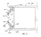
- FIG. 9 is a block diagram showing an embodiment of the ejector latch in an open position, where the ejector latch is disengaged from a groove in a carrier surface.
- FIG. 10 is a block diagram showing an embodiment of the ejector latch in a closed position, where the ejector latch is engaged in a groove in a carrier surface.
- FIG. 11 is a block diagram of a perspective view of an ejector latch in the closed position, in accordance with another embodiment of the invention.
- FIG. 12 is a block diagram of a perspective view of the ejector latch of FIG. 11 in the open position, in accordance with another embodiment of the invention.
- FIG. 13 is a block diagram of a side view of an ejector latch in accordance with another embodiment of the invention, where the movable handle is configured to rotate or pivot with respect to the latch handle portion.
- FIG. 1 is a block diagram illustrating the components of an ejector latch 100 , in accordance with an embodiment of the invention.
- An embodiment of the ejector latch 100 includes the following components.
- a latch handle portion 105 forms the basic handle portion of the ejector latch 100
- a movable handle portion 110 forms the movable (or extendable) portion that is attached to the latch handle portion 105 .
- a latch base 115 attaches to a face plate of a circuit pack (e.g., face plate 305 of a circuit pack 310 in FIG. 3 ).
- a handle release tab 120 allows the movable handle portion 110 to disengage and extend away from the latch handle portion 105 , in order to allow the circuit pack 310 to disengage from a carrier (e.g., 805 in FIG. 8 ), as discussed below.
- a carrier e.g. 805 in FIG. 8
- the circuit pack 310 can be secured to the carrier, as discussed below.
- a handle stop pin 125 inserted into handle stop hole 126 prevents the movable handle portion 110 from completely disengaging from the latch handle portion 105 .
- the movable handle portion 110 can slide on a track 130 of the latch handle portion 105 .
- a pivot pin 135 allows the ejector latch 100 to pivot or rotate out of the way from the components or edges of, for example, a carrier 805 (see FIG. 8 ) so that the circuit pack 310 can be pulled out of the carrier 805 .
- the circuit pack 310 can be pulled in the direction 315 after the ejector latch 100 is rotated out of the way of the components or edges of the carrier 805 . This operation is described in additional detail below with reference to FIG. 8 .
- An optional label 140 may identify, for example, the name of a circuit pack 310 that is affixed to the ejector latch 100 .
- the label 140 is an optional component.
- a spring 145 permits the latch handle portion 105 to separate from the movable handle portion 110 .
- the spring 145 pushes up against the handle release tab 120 . This permits the movable handle portion 110 to be locked in place against the latch handle portion 105 when the movable handle portion 110 is closed (pushed) against the latch handle portion 105 .
- the handle release tab 120 is pressed by the user, the movable handle portion 110 can disengage away from the latch handle portion 105 , and as a result, the ejector latch 100 can be rotated out a few degrees by the spring 145 to allow the circuit pack to be disengaged from, for example, a carrier 805 .
- latch handle portion 105 the movable handle portion 110 , and the latch base 115 , as shown in the drawings, are provided as particular examples.
- the latch handle portion 105 , the movable handle portion 110 , and the latch base 115 may be shaped and/or configured in other manners without departing from the scope of embodiments of the invention.
- a method for assembling the ejector latch 100 can be performed based upon the following steps.
- a latch handle portion 105 is provided.
- a movable handle portion 110 is attached to the latch handle portion 105 .
- the movable handle portion 110 is movingly coupled to the latch handle portion 105 .
- the latch handle portion 105 is attached to a latch base 115 .
- the latch base 115 may be attached to a face plate 305 .
- the face plate 305 is attached to a circuit pack 310 .
- FIG. 2 is a block diagram illustrating the ejector latch 100 in a closed (and locked) position. In this closed position, the movable handle portion 110 is pressed against the latch handle portion 105 and is locked in place against the latch handle portion 105 .
- FIG. 3 is a block diagram illustrating the ejector latches 100 A and 100 B attached to the face plate 305 of the circuit pack 310 .
- the ejector latch 100 A is shown in a closed and locked position, where the movable handle portion 110 A is locked in place against the latch handle portion 105 A.
- the ejector latch 100 B is shown in an extended and unlocked position, where the movable handle portion 110 B is unlocked and extended away from the latch handle portion 105 B (i.e., the movable handle portion 110 B is extended away from the latch handle portion 105 B).
- the ejector latch 100 B can be rotated in the direction 320 away from the face plate 305 .
- the latch base 115 B is attached to the faceplate 305 and the spring 145 B is shown in the open position.
- circuit packs 310 from various manufacturers (e.g., CIENA CORPORATION) may be used with the ejector latches 100 but the invention is not limited thereto. Indeed a wide variety of circuit packs would benefit from the inventive latch designs disclosed here including but not limited to circuit packs containing optical, electrical, and/or opto-electrical components.
- circuit packs 310 that may be used with the ejector latches 100 include, but are not limited to, the circuit packs from CIENA CORPORATION having the following product numbers: PXADMS01: PHANTOM, BOM, SYNC CARD FOR OC48ADM; DXMUX192 ASSY, 10G SONET/SDH, MUX, MODULE; and DXMUXDE2ASSY, GIGABIT MUX 1310 NM, as well as other suitable circuit packs from other manufacturers or vendors.
- the circuit pack 310 can typically be inserted into and can be remove from a carrier, such as, for example, the carrier 805 in FIG. 8 .
- the carrier may, for example, include equipment that is used for a communication network.
- FIG. 4A is a block diagram illustrating a side view of an ejector latch 100 in a closed and locked position.
- the movable handle portion 110 is pressed against the latch handle portion 105 .
- the handle release tab 120 is pressed, the movable handle portion 110 can unlock from the latch handle portion 105 and slide in the direction of arrow 405 away from the latch handle portion 105 .
- FIG. 4B is a block diagram illustrating a side view of a conventional ejector latch 450 .
- the conventional ejector latch 450 does not include any movable or extendable handle components.
- An example of a conventional latch is the a latch with the product number, 485-00013-00 MECH, SUB-ASSY, LATCH, FRONT PANEL, from CIENA CORPORATION, although the latch 450 may represent other types of conventional latches.
- FIG. 5A is a block diagram illustrating a side view of an ejector latch 100 in an open and unlocked position.
- the movable handle portion 110 is extended away from the latch handle portion 105 .
- the ejector latch 100 will be longer in length (for example, length “D” where D is a suitable length that can be varied) than the conventional latch 450 shown in FIG. 5B .
- the ejector latch 100 can be extended by the length D, sufficient force or leverage can be provided by the user by grabbing the latch handle portion 110 to disengage the ejector latch from a portion or component of a carrier.
- the movable handle portion 110 provides an additional ability to pull out the ejector latch 100 from the portion or component of the carrier, since more force can now be applied to the ejector latch 100 .
- the conventional latch 450 is unable to adequately provide the function of easily pulling/disengaging the connector.
- a smaller faceplate and smaller form factor circuit pack design means that the conventional ejector latches do not have sufficient leverage to eject the circuit pack.
- Making the handle of the conventional ejector latch at a longer fixed length to provide more pulling leverage for the user is not an attractive option because the longer fixed length handle would consume valuable face plate real estate that is needed for other purposes such as for connectors, indicators, ESD prevention devices, and/or other purposes.
- the movable handle portion 110 feature of the ejector latch 100 saves face plate real estate or surface area.
- a handle portion 110 that can extend, for example, one inch, saves approximately two inches in face plate room, when the movable handle portion 110 is locked against the latch handle portion 105 in the closed position.
- one (1) inch in height and one (1) inch in length are saved in face plate space when the movable handle portion 110 is locked against the latch handle portion 105 .
- a square inch of valuable faceplate real estate is conserved by embodiments of the invention and such real estate can now be used for other purposes as described herein.
- the handle release tab 120 is seen through a hole 605 of the movable handle portion 110 and is pressed in order to release (slide out and unlock) the movable handle portion 110 away from the latch handle portion 105 .
- the tab 120 is shifted downward by the user and the spring 145 ( FIG. 1 ) disengages the movable handle portion 110 and the movable handle portion 110 can then slide out.
- the tab 120 is pressed down and the movable handle portion 110 can then slide towards the latch handle portion 105 and lock in place as shown in FIG. 6 .
- FIG. 7 is another block diagram illustrating a side view of an ejector latch 100 in an open and unlocked position, in one embodiment of the invention.
- the movable handle portion 110 is extended away the latch handle portion 105 in order to unlock the ejector latch 100 .
- the user can grab the movable handle portion 110 and rotate the latch handle portion 105 and the movable handle portion 110 in the direction of arrow 705 .
- the latch handle portion 105 can pivot away from the latch base 115 at pivot pin 135 , also in the direction of arrow 705 .
- the user can also grab the movable handle portion 110 and rotate the latch handle portion 105 and the movable handle portion 110 in the direction of arrow 710 to pivot the portions 105 and 110 toward the latch base 115 . These pivot actions are illustrated in additional detail in FIGS. 9 and 10 below.
- FIG. 8 is a block diagram illustrating an embodiment of an ejector latches 100 A and 100 B that are attached to a faceplate 305 of a circuit pack 310 , where the circuit pack 310 is insertable into and removable from a carrier 805 .
- the ejector latches 100 A and 100 B are in the locked position, where the latch handles 105 A and 105 B and the movable handles 110 A and 110 B can not pivot away from the latch base 115 which is attached to the faceplate 305 .
- the ejector latches 100 A and 100 B are placed by the user in this locked position after the circuit pack 310 is inserted in a track 801 of the carrier 805 .
- FIG. 10 for a more detailed illustration of the ejector latches 100 A and 100 B in the locked position while disposed in a carrier 805 .
- the circuit pack 310 can be inserted into one of the tracks 801 of the carrier 805 by sliding the circuit pack 310 , generally in the direction of arrow 815 . After the circuit pack 310 are inserted into the track 801 , the ejector latches 100 A and 100 B are placed into the locked position. The circuit pack 310 can be removed from one of the tracks 801 of the carrier 805 by sliding the circuit pack 310 , generally in the direction of arrow 810 . Prior to removing the circuit pack 310 from the track 801 , the ejector latches 100 A and 100 B are placed into the unlocked position.
- the circuit pack 310 can be engaged and disengaged from the carrier 805 based upon the position of the ejector latches 100 A and 100 B against the portions 820 A and 820 B, respectively, of the carrier 805 .
- FIG. 9 is a block diagram showing an embodiment of the ejector latches 100 A and 100 B in an open and unlocked position, where the ejector latches 100 A and 100 B are disengaged from grooves 902 A and 902 B, respectively, in carrier portions 820 A and 820 B of carrier 805 .
- the ejector latches 100 A and 100 B may be engaged and disengaged to other types of openings in the carrier portions 820 A and 820 B, and as a result, the grooves 902 A and 902 B may be replaced by other types of openings for receiving the latch handle portions 105 A and 105 B.
- the movable handle portion 110 A of ejector latch 100 A is extended away from the latch handle portion 105 A to unlock the ejector latch 100 A.
- the movable handle portion 110 A and latch handle portion 105 A can be rotated in the direction 905 so that the latch handle portion 105 A is disengaged from the groove 902 A.
- the movable handle portion 110 B of ejector latch 100 B is extended away from the latch handle portion 105 B to unlock the ejector latch 100 B.
- the movable handle portion 110 B and latch handle portion 105 B are then rotated so that the latch handle portion 105 B is disengaged from the groove 902 B.
- the circuit pack 310 can be disengaged from the carrier 805 since the ejector latches 100 A and 100 B have been disengaged from the portions 820 A and 820 B, respectively, of the carrier 805 .
- FIG. 10 is a block diagram showing an embodiment of the ejector latches 100 A and 100 B in a closed position, where the ejector latches 100 A and 100 B are engaged in the grooves 902 A and 902 B, respectively, in the carrier portion 820 .
- the movable handle portions 110 A and latch handle portion 105 A of ejector latch 100 A can be rotated in the direction 910 ( FIG. 9 ) so that the latch handle portion 105 A is engaged within the groove 902 A.
- the movable handle portion 110 A is then pushed against the latch handle portion 105 A to lock the ejector latch 100 A.
- the movable handle portions 110 B and latch handle portion 105 B of ejector latch 100 B can be rotated so that the latch handle portion 105 B is engaged within the groove 902 B.
- the movable handle portion 110 B is then pushed against the latch handle portion 105 B of ejector latch 100 B to lock the ejector latch 100 B.
- the circuit pack 310 can be securely engaged to the carrier 805 since the ejector latches 100 A and 100 B have been locked into the grooves 902 A and 902 B, respectively, in the portions 820 A and 820 B of the carrier 805 .
- FIG. 11 is a block diagram illustrating an ejector latch 1100 in a closed and locked position, in accordance with another embodiment of the invention.
- the latch handle portion and the movable handle portion of an ejector latch may vary in shape and/or configuration.
- the latch handle portion 1105 forms a substantial portion of the ejector latch 1100
- the movable handle portion 1110 is reduced in surface size and can extend away (as shown by arrow 1115 ) from the latch handle portion 1105 or can be closed against the latch handle portion 1105 (as shown by arrow 1120 ) to lock the movable handle portion 1110 against the latch handle portion 1105 .
- Other shapes for the latch handle portion 1105 and/or movable handle portion 1110 and/or base 115 may be provided.
- FIG. 12 is a block diagram of a perspective view of the ejector latch 1100 of FIG. 11 in the open and unlocked position, in accordance with another embodiment of the invention.
- the movable handle portion 1110 is unlocked from the latch handle portion 1105 and can slide in the direction of arrow 1115 away from the latch handle portion 1105 .
- the movable handle portion 1110 can slide along a track 1205 in the ejector latch 1100 .
- the ejector latch 1100 When the movable handle portion 1110 is extended away from the latch handle portion 1105 , the ejector latch 1100 is unlocked. When the ejector latch 1100 is unlocked, the user can grab the movable handle portion 1110 and rotate the latch handle portion 1105 and the movable handle portion 1110 in the direction of arrow 1215 . The latch handle portion 1105 can pivot away from the latch base 115 at pivot pin 1210 in the direction of arrow 1215 . The user can also grab the movable handle portion 1110 and rotate the latch handle portion 1105 and the movable handle portion 1110 in the direction of arrow 1220 to pivot the portions 1105 and 1110 toward the latch base 115 . These pivot actions were similarly described above.
- FIG. 13 is a block diagram of a side view of an ejector latch 1300 in accordance with another embodiment of the invention, where the movable handle portion 1310 is conf igured to rotate or flip away from the latch handle portion 1305 , in the direction of arrow 1315 . Therefore, when the user presses the tab 1302 , the user can unlock and disengage the movable handle portion 1310 from the latch handle portion 1305 . The user can then rotate the movable handle portion 1310 (including end portion 1311 ) in the direction of arrow 1315 . The latch handle portion 1305 can then pivot away from the latch base 115 at pivot pin 1310 in the direction of arrow 1315 , and the latch handle portion 1305 can disengage from, for example, a portion of a carrier 805 as similarly described above.
- the movable handle portion (e.g., movable handle portions 110 , 810 , or 1310 ) can be formed from plastic or metal. Of course a variety of other materials could be used as long as they have the necessary material properties such as sufficient structural rigidity, machinability (or moldability), or the like.
- the movable handle portion 110 can be formed from carbon fiber composite for strength and electrical conductivity.
Landscapes
- Engineering & Computer Science (AREA)
- Microelectronics & Electronic Packaging (AREA)
- Mounting Of Printed Circuit Boards And The Like (AREA)
Abstract
Description
Claims (14)
Priority Applications (1)
| Application Number | Priority Date | Filing Date | Title |
|---|---|---|---|
| US10/753,438 US7023704B1 (en) | 2004-01-09 | 2004-01-09 | Ejector latch |
Applications Claiming Priority (1)
| Application Number | Priority Date | Filing Date | Title |
|---|---|---|---|
| US10/753,438 US7023704B1 (en) | 2004-01-09 | 2004-01-09 | Ejector latch |
Publications (1)
| Publication Number | Publication Date |
|---|---|
| US7023704B1 true US7023704B1 (en) | 2006-04-04 |
Family
ID=36102023
Family Applications (1)
| Application Number | Title | Priority Date | Filing Date |
|---|---|---|---|
| US10/753,438 Expired - Fee Related US7023704B1 (en) | 2004-01-09 | 2004-01-09 | Ejector latch |
Country Status (1)
| Country | Link |
|---|---|
| US (1) | US7023704B1 (en) |
Cited By (14)
| Publication number | Priority date | Publication date | Assignee | Title |
|---|---|---|---|---|
| WO2008037522A1 (en) * | 2006-09-25 | 2008-04-03 | Robert Bosch Gmbh | Cable harness plug comprising an extensible lever |
| US20100107395A1 (en) * | 2006-06-23 | 2010-05-06 | Adc Gmbh | Latch and handle arrangement for a telecommunications panel |
| US20100278539A1 (en) * | 2009-05-01 | 2010-11-04 | Kasbeer-Betty Rebecca Anne | Ejector apparatus and associated assembly method for pluggable transceivers |
| US20120162956A1 (en) * | 2010-12-25 | 2012-06-28 | Hon Hai Precision Industry Co., Ltd. | Electronic device having easily assembling structure |
| US20130050964A1 (en) * | 2011-08-31 | 2013-02-28 | Japan Aviation Electronics Industry Limited | Connector |
| US9398720B1 (en) | 2014-05-30 | 2016-07-19 | Emc Corporation | Chassis with airflow and thermal management |
| US9603280B2 (en) | 2014-05-30 | 2017-03-21 | EMC IP Holding Company LLC | Flash module |
| US10080300B1 (en) | 2015-12-29 | 2018-09-18 | EMC IP Holding Company LLC | Mechanical latch module |
| US20200004300A1 (en) * | 2018-06-29 | 2020-01-02 | Lenovo (Beijing) Co., Ltd. | Electronic device |
| US10638631B2 (en) | 2018-09-25 | 2020-04-28 | Ciena Corporation | Compliant micro latch for high-speed signal sub-slot pluggable modules |
| CN111565529A (en) * | 2019-02-13 | 2020-08-21 | 发那科株式会社 | Panel and electronic device |
| US11079559B2 (en) | 2019-04-23 | 2021-08-03 | Ciena Corporation | Universal sub slot architecture for networking modules |
| US11464128B2 (en) | 2019-02-13 | 2022-10-04 | Fanuc Corporation | Electronic device |
| US11736195B2 (en) | 2019-04-23 | 2023-08-22 | Ciena Corporation | Universal sub slot architecture for networking modules |
Citations (6)
| Publication number | Priority date | Publication date | Assignee | Title |
|---|---|---|---|---|
| US5414594A (en) * | 1993-12-14 | 1995-05-09 | Vsi Corporation | Self-adjusting insertion/extraction apparatus for printed circuit boards |
| US6094353A (en) * | 1997-02-03 | 2000-07-25 | Siemens Aktiengesellschaft | Front system for printed circuit boards in mounting racks having a latchable lever pull handle |
| US6443315B1 (en) * | 2000-07-28 | 2002-09-03 | Mitsubishi Denki Kabushiki Kaisha | Insertion and removal system in plug-in unit |
| US6512679B1 (en) * | 2001-11-02 | 2003-01-28 | Nortel Networks Limited | Variable insertion force circuit pack latching system |
| US6587350B1 (en) * | 2002-05-16 | 2003-07-01 | Inventec Corporation | Ejection mechanism for modular electronic element |
| US6646883B2 (en) * | 2001-08-21 | 2003-11-11 | Hewlett-Packard Development Company, L.P. | Insertion latch and ejectable pull handle for rack mounted electronic devices |
-
2004
- 2004-01-09 US US10/753,438 patent/US7023704B1/en not_active Expired - Fee Related
Patent Citations (6)
| Publication number | Priority date | Publication date | Assignee | Title |
|---|---|---|---|---|
| US5414594A (en) * | 1993-12-14 | 1995-05-09 | Vsi Corporation | Self-adjusting insertion/extraction apparatus for printed circuit boards |
| US6094353A (en) * | 1997-02-03 | 2000-07-25 | Siemens Aktiengesellschaft | Front system for printed circuit boards in mounting racks having a latchable lever pull handle |
| US6443315B1 (en) * | 2000-07-28 | 2002-09-03 | Mitsubishi Denki Kabushiki Kaisha | Insertion and removal system in plug-in unit |
| US6646883B2 (en) * | 2001-08-21 | 2003-11-11 | Hewlett-Packard Development Company, L.P. | Insertion latch and ejectable pull handle for rack mounted electronic devices |
| US6512679B1 (en) * | 2001-11-02 | 2003-01-28 | Nortel Networks Limited | Variable insertion force circuit pack latching system |
| US6587350B1 (en) * | 2002-05-16 | 2003-07-01 | Inventec Corporation | Ejection mechanism for modular electronic element |
Cited By (25)
| Publication number | Priority date | Publication date | Assignee | Title |
|---|---|---|---|---|
| US20100107395A1 (en) * | 2006-06-23 | 2010-05-06 | Adc Gmbh | Latch and handle arrangement for a telecommunications panel |
| US7970250B2 (en) * | 2006-06-23 | 2011-06-28 | Adc Gmbh | Method of removing a telecommunications panel from a frame |
| WO2008037522A1 (en) * | 2006-09-25 | 2008-04-03 | Robert Bosch Gmbh | Cable harness plug comprising an extensible lever |
| US20100278539A1 (en) * | 2009-05-01 | 2010-11-04 | Kasbeer-Betty Rebecca Anne | Ejector apparatus and associated assembly method for pluggable transceivers |
| US8052335B2 (en) * | 2009-05-01 | 2011-11-08 | Ciena Corporation | Ejector apparatus and associated assembly method for pluggable transceivers |
| US20120162956A1 (en) * | 2010-12-25 | 2012-06-28 | Hon Hai Precision Industry Co., Ltd. | Electronic device having easily assembling structure |
| US8614895B2 (en) * | 2010-12-25 | 2013-12-24 | Hong Fu Jin Precision Industry (Shenzhen) Co., Ltd. | Electronic device having easily assembling structure |
| US20130050964A1 (en) * | 2011-08-31 | 2013-02-28 | Japan Aviation Electronics Industry Limited | Connector |
| US8811025B2 (en) * | 2011-08-31 | 2014-08-19 | Japan Aviation Electronics Industry, Limited | Connector |
| US9999154B2 (en) | 2014-05-30 | 2018-06-12 | EMC IP Holding Company LLC | Flash module |
| US9622394B1 (en) | 2014-05-30 | 2017-04-11 | EMC IP Holding Company LLC | Electromagnetic interference containment system |
| US9398720B1 (en) | 2014-05-30 | 2016-07-19 | Emc Corporation | Chassis with airflow and thermal management |
| US10238016B2 (en) | 2014-05-30 | 2019-03-19 | EMC IP Holding Company LLC | Electromagnetic interference containment system |
| US9603280B2 (en) | 2014-05-30 | 2017-03-21 | EMC IP Holding Company LLC | Flash module |
| US10080300B1 (en) | 2015-12-29 | 2018-09-18 | EMC IP Holding Company LLC | Mechanical latch module |
| US10901468B2 (en) * | 2018-06-29 | 2021-01-26 | Lenovo (Beijing) Co., Ltd. | Electronic device |
| US20200004300A1 (en) * | 2018-06-29 | 2020-01-02 | Lenovo (Beijing) Co., Ltd. | Electronic device |
| US10638631B2 (en) | 2018-09-25 | 2020-04-28 | Ciena Corporation | Compliant micro latch for high-speed signal sub-slot pluggable modules |
| CN111565529A (en) * | 2019-02-13 | 2020-08-21 | 发那科株式会社 | Panel and electronic device |
| US11464128B2 (en) | 2019-02-13 | 2022-10-04 | Fanuc Corporation | Electronic device |
| CN111565529B (en) * | 2019-02-13 | 2022-11-29 | 发那科株式会社 | Panel and electronic device |
| US12041743B2 (en) | 2019-02-13 | 2024-07-16 | Fanuc Corporation | Faceplate and electronic device |
| US11079559B2 (en) | 2019-04-23 | 2021-08-03 | Ciena Corporation | Universal sub slot architecture for networking modules |
| US11736195B2 (en) | 2019-04-23 | 2023-08-22 | Ciena Corporation | Universal sub slot architecture for networking modules |
| US12537606B2 (en) | 2019-04-23 | 2026-01-27 | Ciena Corporation | Universal sub slot architecture for networking modules |
Similar Documents
| Publication | Publication Date | Title |
|---|---|---|
| US7023704B1 (en) | Ejector latch | |
| US8009424B2 (en) | Latching device and electronic device using the same | |
| US10206302B2 (en) | Ejector latch assembly and system for securing a board within a frame | |
| US7872860B2 (en) | Portable apparatus, fastening device and locking mechanism thereof | |
| US7955003B2 (en) | Bail release mechanism for communications module | |
| US9958912B2 (en) | Two rack unit chassis and low profile tool-less hard drive carrier | |
| US5269698A (en) | Retaining and release mechanism for computer storage devices including a pawl latch assembly | |
| US6129572A (en) | Electrical connector with latch to retain IC card | |
| WO2006024913A3 (en) | Cassette locking and ejecting arrangement | |
| US8059395B2 (en) | Mounting apparatus and electronic device incorporating the same | |
| US8544967B2 (en) | Server rack | |
| US20030142917A1 (en) | Pull detach mechanism for fiber optic transceiver module | |
| US10795101B2 (en) | Optical module | |
| US7575453B2 (en) | Electronic module locking and ejecting apparatus | |
| US20060209501A1 (en) | Computer enclosure | |
| US20100024304A1 (en) | Battery cover latch mechanism and portable electronic device using same | |
| US8614894B2 (en) | Electronic device assembly having protecting mechanism | |
| US20120235002A1 (en) | Mounting apparatus | |
| US20130301194A1 (en) | Electronic device having foldable cover | |
| EP2274662B1 (en) | Cable management module | |
| US6147878A (en) | Secure latch locking clip | |
| US20110095547A1 (en) | Battery cover latching mechanism | |
| EP2744048B1 (en) | Self-ejectable port fixing device | |
| US7948745B2 (en) | Release module and computer housing using the same | |
| US20100124699A1 (en) | Battery cover latching mechanism |
Legal Events
| Date | Code | Title | Description |
|---|---|---|---|
| FEPP | Fee payment procedure |
Free format text: PAYOR NUMBER ASSIGNED (ORIGINAL EVENT CODE: ASPN); ENTITY STATUS OF PATENT OWNER: LARGE ENTITY |
|
| FPAY | Fee payment |
Year of fee payment: 4 |
|
| FPAY | Fee payment |
Year of fee payment: 8 |
|
| AS | Assignment |
Owner name: DEUTSCHE BANK AG NEW YORK BRANCH, NEW YORK Free format text: SECURITY INTEREST;ASSIGNOR:CIENA CORPORATION;REEL/FRAME:033329/0417 Effective date: 20140715 |
|
| AS | Assignment |
Owner name: BANK OF AMERICA, N.A., AS ADMINISTRATIVE AGENT, NORTH CAROLINA Free format text: PATENT SECURITY AGREEMENT;ASSIGNOR:CIENA CORPORATION;REEL/FRAME:033347/0260 Effective date: 20140715 Owner name: BANK OF AMERICA, N.A., AS ADMINISTRATIVE AGENT, NO Free format text: PATENT SECURITY AGREEMENT;ASSIGNOR:CIENA CORPORATION;REEL/FRAME:033347/0260 Effective date: 20140715 |
|
| FEPP | Fee payment procedure |
Free format text: PAYER NUMBER DE-ASSIGNED (ORIGINAL EVENT CODE: RMPN); ENTITY STATUS OF PATENT OWNER: LARGE ENTITY Free format text: PAYOR NUMBER ASSIGNED (ORIGINAL EVENT CODE: ASPN); ENTITY STATUS OF PATENT OWNER: LARGE ENTITY |
|
| FEPP | Fee payment procedure |
Free format text: MAINTENANCE FEE REMINDER MAILED (ORIGINAL EVENT CODE: REM.) |
|
| LAPS | Lapse for failure to pay maintenance fees |
Free format text: PATENT EXPIRED FOR FAILURE TO PAY MAINTENANCE FEES (ORIGINAL EVENT CODE: EXP.) |
|
| STCH | Information on status: patent discontinuation |
Free format text: PATENT EXPIRED DUE TO NONPAYMENT OF MAINTENANCE FEES UNDER 37 CFR 1.362 |
|
| FP | Lapsed due to failure to pay maintenance fee |
Effective date: 20180404 |
|
| AS | Assignment |
Owner name: CIENA CORPORATION, MARYLAND Free format text: RELEASE BY SECURED PARTY;ASSIGNOR:DEUTSCHE BANK AG NEW YORK BRANCH;REEL/FRAME:050938/0389 Effective date: 20191028 |
|
| AS | Assignment |
Owner name: BANK OF AMERICA, N.A., AS COLLATERAL AGENT, ILLINO Free format text: PATENT SECURITY AGREEMENT;ASSIGNOR:CIENA CORPORATION;REEL/FRAME:050969/0001 Effective date: 20191028 Owner name: BANK OF AMERICA, N.A., AS COLLATERAL AGENT, ILLINOIS Free format text: PATENT SECURITY AGREEMENT;ASSIGNOR:CIENA CORPORATION;REEL/FRAME:050969/0001 Effective date: 20191028 |
|
| AS | Assignment |
Owner name: CIENA CORPORATION, MARYLAND Free format text: RELEASE BY SECURED PARTY;ASSIGNOR:BANK OF AMERICA, N.A.;REEL/FRAME:065630/0232 Effective date: 20231024 |