US701094A - Fire-escape. - Google Patents
Fire-escape. Download PDFInfo
- Publication number
- US701094A US701094A US5841701A US1901058417A US701094A US 701094 A US701094 A US 701094A US 5841701 A US5841701 A US 5841701A US 1901058417 A US1901058417 A US 1901058417A US 701094 A US701094 A US 701094A
- Authority
- US
- United States
- Prior art keywords
- walls
- rope
- box
- sections
- reel
- Prior art date
- Legal status (The legal status is an assumption and is not a legal conclusion. Google has not performed a legal analysis and makes no representation as to the accuracy of the status listed.)
- Expired - Lifetime
Links
Images

Classifications
-
- A—HUMAN NECESSITIES
- A62—LIFE-SAVING; FIRE-FIGHTING
- A62B—DEVICES, APPARATUS OR METHODS FOR LIFE-SAVING
- A62B1/00—Devices for lowering persons from buildings or the like
- A62B1/06—Devices for lowering persons from buildings or the like by making use of rope-lowering devices
- A62B1/08—Devices for lowering persons from buildings or the like by making use of rope-lowering devices with brake mechanisms for the winches or pulleys
- A62B1/10—Devices for lowering persons from buildings or the like by making use of rope-lowering devices with brake mechanisms for the winches or pulleys mechanically operated
Definitions
- This invention relates to a fire-escape of that class in which a line or rope is provided for the descent of a person, and this rope is used in connection with certain governing mechanism for causing it to be paid out at a uniform rate.
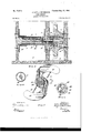
- Figure 1 is a sectional View showing the invention applied to a building.
- Fig. 2 is a plan View of the parts in operating adjustment.
- Fig. 3 is a detail perspective view showing one of the truss-sections which are employed in connection with the outrigger.
- Fig. 4 is an enlarged section of the governor mechanism.
- Fig. 5 is a section on the line 5 5 of Fig. 4.
- Fig. 6 is a section on the line 6 6 of Fig. 4, and
- Fig. 7 is a sectional elevation on the line 7 7 of Fig. 4.
- the mechanism is mounted in a suitable framing comprising a box 8, carrying the governor mechanism, and a box 9, carryinga reel 10, over which is wound the rope 11.
- the box 9 has two of its walls, which are indicated at 12, connected together by ahinge, as indicated at 14. These walls 12 form an outrigger, which is connected by a hinge to the stationary walls of the box 9, as indicated at 15.
- the walls 12 are capable of folding inward, as shown by full lines in Fig. 1, or of being thrown outward, as indicated bydotted lines, in which position the outrigger-walls extend through the window and project out from the walls of the building for a purpose which will appear hereinafter.
- Applied to each of the walls 12 of the box 9 are two truss-sections 16, which are fastened rigidly to their respective walls 12 and which are provided with interlocking laterally-projected flanges 17.
- the reel 10 is mounted at one end on a stub-shaft 22, fastened to one of the stationary side walls of the box 9, and the other end of the reel is fastened to a shaft 23, which is mounted loosely in a bearing 24, carried in the opposite side wall of the box 9.
- a spring 25 is arranged around a longitudinal extension 26 of the stub-shaft 22 and connected, respectively, with the stubshaft and with the reel 10. This spring 25 is of such character as to permit the reel to unwind sufllciently to lower the person escaping from the building to the ground, and then when the weight of such person is removed from the rope the spring 25 will assertitself and rewind the rope on the drum.
- the shaft 23 projects into the box 8 and Fig, 1.
- Pivotally mounted on the clutch member 29 are centrifugally-actuated governor-arms 32,whi ch are provided with brakefingers 33, arranged to bear on the outer periphery of the stub-shaft 31 when the arms 32 are thrown outward upon the revolution of the clutch member 29.
- Springs 34 are connected with the governor-arms 32 and tend to throw them inward to inactive position.
- the brake-fingers 33 engage the stub-shaft or stationary brake member 31, and thus the action of the reel is retarded. It will be seen that this mechanism will effectively govern the movement of the reel and prevent it from unwinding at a dangerous rate of speed.
- the movable walls 12 of the box 9 should be thrown outward, as indicated by dotted lines in Fig. l, to form the outrigger.
- the person descending should then grasp the outer end of the rope.
- the rope may be provided with a sling or harness in which aperson may be comfortably and securely seated, and in practice we will fit the apparatus with such a device.
- the reel 10 will unwind against the spring 25, and then as the reel revolves sufficiently fast the governor will be thrown into action and the descent of the person regulated.
- the rope 11 will be automatically rewound for a second ascent.
- a slight line or cord attached to the rope may be used for preventing the rope from rewinding too rapidly and avoid the liability of its becoming tangled on the reel.
Description
N0. 701,094. Patented May r902.
J. & P. J. SETBAGKEN.
F l R E E S G A P E.
(Application filed. May 2, 1901.\
(No Model.) 2 Sheets-Sheet l.
WITNESSES No. 701,094. Patented May 27, I902.
.J. &. P. J. SETBABKEN.
FIRE ESCAPE (Application filed May 2, 1901.\ v 0 dBL) 2 Shaets$haet 2,
ziw
-n Nouns PETERS co Womumo.v msumcwn, o c
UNTTnn STATES PATENT OFFICE.
JULIUS SETBACKEN AND PETER J. SETBACKEN, OF CYNTIIIANA, INDIANA.
FiRE-ESCAPE.
SPECIFICATION forming part of Letters Patent No. 701,094, dated May 27, 1902.
Application filed May 2, 1901- Serial No. 58,417. (No model.) 7
To all whom it puny concern:
Be it known that We,JULIUSSETBAOKEN and PETER J. SETBAOKEN, citizens of the United States, and residents of Oynthiana, in the county of Posey and State of Indiana, have invented a new and Improved Fire-Escape, of which the following is a full, clear, and exact description.
This invention relates to a fire-escape of that class in which a line or rope is provided for the descent of a person, and this rope is used in connection with certain governing mechanism for causing it to be paid out at a uniform rate.
This specification is a specific description of one form of the invention, while the claims are definitions of the actual scope thereof.
Reference is to be had to the accompanying drawings, forming a part of this specification, in which similar characters of reference indicate corresponding parts in all the views.
Figure 1 is a sectional View showing the invention applied to a building. Fig. 2 is a plan View of the parts in operating adjustment. Fig. 3 is a detail perspective view showing one of the truss-sections which are employed in connection with the outrigger.
Fig. 4 is an enlarged section of the governor mechanism. Fig. 5 is a section on the line 5 5 of Fig. 4. Fig. 6 is a section on the line 6 6 of Fig. 4, and Fig. 7 is a sectional elevation on the line 7 7 of Fig. 4.
The mechanism is mounted in a suitable framing comprising a box 8, carrying the governor mechanism, and a box 9, carryinga reel 10, over which is wound the rope 11. The box 9 has two of its walls, which are indicated at 12, connected together by ahinge, as indicated at 14. These walls 12 form an outrigger, which is connected by a hinge to the stationary walls of the box 9, as indicated at 15. The walls 12 are capable of folding inward, as shown by full lines in Fig. 1, or of being thrown outward, as indicated bydotted lines, in which position the outrigger-walls extend through the window and project out from the walls of the building for a purpose which will appear hereinafter. Applied to each of the walls 12 of the box 9 are two truss-sections 16, which are fastened rigidly to their respective walls 12 and which are provided with interlocking laterally-projected flanges 17.
(Best shown in Fig. 3.) When the walls 12 are thrown outward to lie in thesame plane, thefianges 17 engage together in pairs, and then the sections 16 form trusses which strengthen the Walls 12 and cause them to retain a rigid connection, thus forming the outrigger, which serves to carry the rope 11 clear of the walls of'the building and prevent persons descending on the fire escape from striking said walls. The rope 11 is led from the drum 10 over a roller 18, arranged at the inner end of the outrigger, and under a guide 19, arranged adjacent to said roller. The rope 11 then passes over a roll 20, arranged at the outer end of the outrigger, on which roll 20the rope is held by means of a guide-plate 21.
As shown bestin Fig. 4, the reel 10 is mounted at one end on a stub-shaft 22, fastened to one of the stationary side walls of the box 9, and the other end of the reel is fastened to a shaft 23, which is mounted loosely in a bearing 24, carried in the opposite side wall of the box 9. A spring 25 is arranged around a longitudinal extension 26 of the stub-shaft 22 and connected, respectively, with the stubshaft and with the reel 10. This spring 25 is of such character as to permit the reel to unwind sufllciently to lower the person escaping from the building to the ground, and then when the weight of such person is removed from the rope the spring 25 will assertitself and rewind the rope on the drum. In this connection we would explain that it would be advisable that the descending end of the rope be connected with a slight cord, which may be held by a person on the ground, so as to prevent the spring 25 from running away with the rope and winding it in tangled condition on the drum.
The shaft 23 projects into the box 8 and Fig, 1.
a stub-shaft 31, carried by one of the walls of V the casing 8. Pivotally mounted on the clutch member 29 are centrifugally-actuated governor-arms 32,whi ch are provided with brakefingers 33, arranged to bear on the outer periphery of the stub-shaft 31 when the arms 32 are thrown outward upon the revolution of the clutch member 29. Springs 34 are connected with the governor-arms 32 and tend to throw them inward to inactive position. As the reel 10 unwinds the clutch member 29 is turned therewith, and as soon as this clutch member acquires suificient speed to overcome the action of the springs 34 the brake-fingers 33 engage the stub-shaft or stationary brake member 31, and thus the action of the reel is retarded. It will be seen that this mechanism will effectively govern the movement of the reel and prevent it from unwinding at a dangerous rate of speed.
- In using the invention the parts when inactive are arranged as shown by full lines in Should a person desire to descend,
I; the movable walls 12 of the box 9 should be thrown outward, as indicated by dotted lines in Fig. l, to form the outrigger. The person descending should then grasp the outer end of the rope. If desired, the rope may be provided with a sling or harness in which aperson may be comfortably and securely seated, and in practice we will fit the apparatus with such a device. As soon as the Weight of the person is placed on the rope 11 the reel 10 will unwind against the spring 25, and then as the reel revolves sufficiently fast the governor will be thrown into action and the descent of the person regulated. When the person reaches the ground, the rope 11 will be automatically rewound for a second ascent. As mentioned above, a slight line or cord attached to the rope may be used for preventing the rope from rewinding too rapidly and avoid the liability of its becoming tangled on the reel.
Various changes in the form, proportions, and minor details of ourinvention may be resorted to without departing from the spirit and scope of our invention. Hence we consider ourselves entitled to allsuch variations as may lie within the scope of our claims.
Having thus described our invention, we claim as new and desire to secure by Letters Patent 1. In a fire-escape, the combination with a reel and means for regulating the movement thereof,of an outrigger comprising two hingeconnected sections, and truss members fastened respectively to the sections and having interlocking parts, for the purpose specified.
2. The combination of two hinge-connected sections, and truss-sections fastened respectively to said hinge-connected sections, the truss-sections having interlocking parts to hold the hinge-connected sections rigid when extended.
3. In a fire-escape,the combination of a box having two of its side walls connected together by a hinge and one of said walls being connected by a hinge to the body of the box, a drum and regulating devices mounted in the box, a rope carried on the drum and guided over the hinge-connected walls thereon when said walls are thrown outward, and truss-sections respectively carried on the hinge-connected sections of the box, said truss-sections having interlocking parts connected together when the hinge-connected walls of the box are thrown into the extended position.
4. Thecombination of adrum,arotary shaft carrying it,a dog-carrier fastened to the shaft, a dog mounted on the carrier, ashaft mounted stationary in alinem cut with the rotary shaft, a clutch member loose on the stationary shaft and inclosing the dog-carrier and dog, said dog working with the interior of the clutch member, weighted arms pivoted on the clutch member, and having brake-fingers, a stationary member forming abraking-surface with which the brake fingers coact, and springs actuating the weighted arms to hold them yieldingly against centrifugal motion.
In testimony whereof we have signed our names to this specification in the presence of two subscribing witnesses.
JULIUS SETBAOKEN. PETER J. SETBAOKEN. Witnesses:
CLAUDIUS MALCOM, GEORGE F. MARTIN.
Priority Applications (1)
| Application Number | Priority Date | Filing Date | Title |
|---|---|---|---|
| US5841701A US701094A (en) | 1901-05-02 | 1901-05-02 | Fire-escape. |
Applications Claiming Priority (1)
| Application Number | Priority Date | Filing Date | Title |
|---|---|---|---|
| US5841701A US701094A (en) | 1901-05-02 | 1901-05-02 | Fire-escape. |
Publications (1)
| Publication Number | Publication Date |
|---|---|
| US701094A true US701094A (en) | 1902-05-27 |
Family
ID=2769625
Family Applications (1)
| Application Number | Title | Priority Date | Filing Date |
|---|---|---|---|
| US5841701A Expired - Lifetime US701094A (en) | 1901-05-02 | 1901-05-02 | Fire-escape. |
Country Status (1)
| Country | Link |
|---|---|
| US (1) | US701094A (en) |
Cited By (9)
| Publication number | Priority date | Publication date | Assignee | Title |
|---|---|---|---|---|
| US2546202A (en) * | 1938-04-02 | 1951-03-27 | Trouin Joseph | Apparatus for protection against falls into space |
| US2553090A (en) * | 1947-10-20 | 1951-05-15 | Oscar M Weatherby | Fire escape drum and cable and hydraulic governor means therefor |
| US2556118A (en) * | 1947-03-01 | 1951-06-05 | Sokolik Edward | Body lowering apparatus |
| US4440261A (en) * | 1980-11-21 | 1984-04-03 | Clark Mark J | Portable high-rise escape device |
| US4653609A (en) * | 1984-11-30 | 1987-03-31 | Devine Millard J | Controlled descent apparatus |
| US6626265B1 (en) | 2001-06-29 | 2003-09-30 | Fids, Inc. | Controlled descent apparatus |
| US20080314685A1 (en) * | 2005-12-14 | 2008-12-25 | Verstegen Eugene Gijsbertus Ma | Devices and Methods For Safely Evacuating an Individual During an Emergency From a Tall Structure |
| US10065053B2 (en) | 2013-08-05 | 2018-09-04 | Evacuator International Property B.V. | Device for evacuating individuals |
| US20210228915A1 (en) * | 2020-01-23 | 2021-07-29 | Pella Corporation | Escape systems for descending a person from a window |
-
1901
- 1901-05-02 US US5841701A patent/US701094A/en not_active Expired - Lifetime
Cited By (9)
| Publication number | Priority date | Publication date | Assignee | Title |
|---|---|---|---|---|
| US2546202A (en) * | 1938-04-02 | 1951-03-27 | Trouin Joseph | Apparatus for protection against falls into space |
| US2556118A (en) * | 1947-03-01 | 1951-06-05 | Sokolik Edward | Body lowering apparatus |
| US2553090A (en) * | 1947-10-20 | 1951-05-15 | Oscar M Weatherby | Fire escape drum and cable and hydraulic governor means therefor |
| US4440261A (en) * | 1980-11-21 | 1984-04-03 | Clark Mark J | Portable high-rise escape device |
| US4653609A (en) * | 1984-11-30 | 1987-03-31 | Devine Millard J | Controlled descent apparatus |
| US6626265B1 (en) | 2001-06-29 | 2003-09-30 | Fids, Inc. | Controlled descent apparatus |
| US20080314685A1 (en) * | 2005-12-14 | 2008-12-25 | Verstegen Eugene Gijsbertus Ma | Devices and Methods For Safely Evacuating an Individual During an Emergency From a Tall Structure |
| US10065053B2 (en) | 2013-08-05 | 2018-09-04 | Evacuator International Property B.V. | Device for evacuating individuals |
| US20210228915A1 (en) * | 2020-01-23 | 2021-07-29 | Pella Corporation | Escape systems for descending a person from a window |
Similar Documents
| Publication | Publication Date | Title |
|---|---|---|
| US701094A (en) | Fire-escape. | |
| US1117098A (en) | Fire-escape. | |
| US425554A (en) | Fire-escape | |
| US936385A (en) | Fire-escape. | |
| US471145A (en) | Fire-escape | |
| US1164489A (en) | Fire-escape. | |
| US839974A (en) | Fire-escape. | |
| US1020065A (en) | Fire-escape. | |
| US1333530A (en) | Fire-escape | |
| US695001A (en) | Fire-escape. | |
| US1123776A (en) | Fire-escape. | |
| US650403A (en) | Fire-escape. | |
| US1016299A (en) | Fire-escape. | |
| US1191504A (en) | Fire-escape. | |
| US702259A (en) | Fire-escape. | |
| US1219530A (en) | Device for lowering bodies. | |
| US646635A (en) | Fire-escape. | |
| US279814A (en) | Fire-escape | |
| US493490A (en) | Fiee escape | |
| US708825A (en) | Fire-escape. | |
| US350473A (en) | Fike escape | |
| US201050A (en) | Improvement in fire-escapes | |
| US772056A (en) | Fire-escape. | |
| US644504A (en) | Fire-escape. | |
| US342108A (en) | Fire-escape |