US7004415B2 - Compact creel - Google Patents
Compact creel Download PDFInfo
- Publication number
- US7004415B2 US7004415B2 US10/642,003 US64200303A US7004415B2 US 7004415 B2 US7004415 B2 US 7004415B2 US 64200303 A US64200303 A US 64200303A US 7004415 B2 US7004415 B2 US 7004415B2
- Authority
- US
- United States
- Prior art keywords
- yarn
- frame
- header
- creel
- packages
- Prior art date
- Legal status (The legal status is an assumption and is not a legal conclusion. Google has not performed a legal analysis and makes no representation as to the accuracy of the status listed.)
- Expired - Lifetime, expires
Links
Images


Classifications
-
- D—TEXTILES; PAPER
- D05—SEWING; EMBROIDERING; TUFTING
- D05C—EMBROIDERING; TUFTING
- D05C15/00—Making pile fabrics or articles having similar surface features by inserting loops into a base material
- D05C15/04—Tufting
- D05C15/08—Tufting machines
- D05C15/16—Arrangements or devices for manipulating threads
- D05C15/18—Thread feeding or tensioning arrangements
-
- B—PERFORMING OPERATIONS; TRANSPORTING
- B65—CONVEYING; PACKING; STORING; HANDLING THIN OR FILAMENTARY MATERIAL
- B65H—HANDLING THIN OR FILAMENTARY MATERIAL, e.g. SHEETS, WEBS, CABLES
- B65H49/00—Unwinding or paying-out filamentary material; Supporting, storing or transporting packages from which filamentary material is to be withdrawn or paid-out
- B65H49/02—Methods or apparatus in which packages do not rotate
- B65H49/04—Package-supporting devices
- B65H49/14—Package-supporting devices for several operative packages
- B65H49/16—Stands or frameworks
-
- B—PERFORMING OPERATIONS; TRANSPORTING
- B65—CONVEYING; PACKING; STORING; HANDLING THIN OR FILAMENTARY MATERIAL
- B65H—HANDLING THIN OR FILAMENTARY MATERIAL, e.g. SHEETS, WEBS, CABLES
- B65H57/00—Guides for filamentary materials; Supports therefor
- B65H57/003—Arrangements for threading or unthreading the guide
-
- B—PERFORMING OPERATIONS; TRANSPORTING
- B65—CONVEYING; PACKING; STORING; HANDLING THIN OR FILAMENTARY MATERIAL
- B65H—HANDLING THIN OR FILAMENTARY MATERIAL, e.g. SHEETS, WEBS, CABLES
- B65H57/00—Guides for filamentary materials; Supports therefor
- B65H57/12—Tubes
-
- B—PERFORMING OPERATIONS; TRANSPORTING
- B65—CONVEYING; PACKING; STORING; HANDLING THIN OR FILAMENTARY MATERIAL
- B65H—HANDLING THIN OR FILAMENTARY MATERIAL, e.g. SHEETS, WEBS, CABLES
- B65H57/00—Guides for filamentary materials; Supports therefor
- B65H57/16—Guides for filamentary materials; Supports therefor formed to maintain a plurality of filaments in spaced relation
-
- B—PERFORMING OPERATIONS; TRANSPORTING
- B65—CONVEYING; PACKING; STORING; HANDLING THIN OR FILAMENTARY MATERIAL
- B65H—HANDLING THIN OR FILAMENTARY MATERIAL, e.g. SHEETS, WEBS, CABLES
- B65H2701/00—Handled material; Storage means
- B65H2701/30—Handled filamentary material
- B65H2701/31—Textiles threads or artificial strands of filaments
Definitions
- This invention relates in general to the field of carpet production, and in particular, to carpet yarn creels.
- Carpet tufting machines are relatively compact devices. However, substantial space within a carpet production facility is required for the entire tufting process. In addition to the space occupied by a tufting machine (i.e. the tufter) itself, there must be roll-up or additional processing equipment, or both, positioned downstream from the tufter.
- Yarn is typically supplied directly to the tufter by one of two methods. It may come from a “creel,” which is a rack holding large bobbins or packages of yarn that spool off of the bobbins and into the tufter. Conventional creels occupy substantial floor space “upstream” from the tufter because of the size of the packages or bobbins of yarn and the space needed to hold them so that the many separate strands of yarn can be pulled off the bobbins and fed into the tufting machine. The floor space required by a standard warper and creel is on the order of 2,000 square feet.
- yarn can be fed to the tufting machine from a “beam,” a large horizontal mandrel onto which multiple strands of yarn of the needed colors are wound in advance. The yarn strands are then unwound simultaneously from the beam into the tufter. While beams typically require substantially less space immediately in front of the tufter than conventional creels, substantial space is needed, and significant work is required to prepare the beam, because in order to position yarn on a beam, bobbins or yarn packages must be positioned on creels to “feed” the beam, much as the yarn packages would be positioned to feed a tufter directly.
- a significant challenge to carpet manufacturers is to reduce the amount of yarn waste occurring in the manufacturing of carpet. Wasted yarn can occur in several stages during the manufacturing process. For example, there can be yarn waste due to tufting beam waste, production beam waste and/or warping beam waste. A cause of waste is the inability to effectively determine the amount of yarn that is needed for a particular piece of carpet. As yarn is fed into a tufting machine it may be realized that yarn length for one color in a pattern is too short while yarn length for another color in the pattern is too long, resulting in wasted yarn. Large bobbins of yarn or beams of yarn compound the problem due to the sheer size of the yarn contained. A compact creel with smaller yarn packages reduces waste in the manufacturing process. Another significant problem is carpet overrun overage.
- This invention is a highly mobile, compact creel that utilizes frames for holding yarn packages (or bobbins), where the packages may be in the form supplied by the yarn supplier (typical sizes are initially about 6 inches or about 10-11 inches in diameter).
- Each frame can hold yarn packages facing front and back.
- Each creel frame can hold, for instance, about 416 yarn packages, for a total of approximately 832 yarn packages, so that the two sides of the frames together hold sufficient yarn ends for a typical carpet tufting machine.
- Other numbers of packages can also be accommodated, and multiple frames can be used to feed a single tufting machine.
- a header having adjustable bars and slots for the yarn mates and affixes to the frame. This header provides for aligning all of the yarn ends in the same plane in order to join them to ends already threaded into the tufting machine.
- yarn spools off of the end of the yarn package, through an eyelet (or yarn eye), through a rigid tube affixed to the frame (and inside the hollow yarn package), and through a flexible tube leading to the top of the frame, and into the header.
- the flexible tube typically passes through the rigid tube on which the package rests and a yarn eye at the end of the rigid tube can be formed on the end of the flexible tube.
- the floor space required for two 16 foot frames of the compact creel of this invention is on the order of 160 square feet.
- a yarn reclamation procedure of this invention strips the yarn packages without unloading the yarn packages from the creel.
- the ends of the yarn tie from head to tail.
- the portable creel is placed in front of a backwinder head, and skinner yarn pieces wind onto one package or a few packages.
- Objects of this invention include:
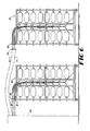
- FIG. 1 is a perspective view of both sides of a compact creel of this invention including a frame, a header, yarn packages on hollow supports and flexible tubing.
- FIG. 2 is an exploded perspective view of a portion of the compact creel of FIG. 1 , including a hollow support for a yarn package shown in broken lines and a support, a flexible yarn tube and a portion of the header.
- FIG. 3 is a side elevation view of a front and rear portion of the creel of FIG. 1 .
- FIG. 4 is a side view, partially in section of the end of a package support tube and flexible tubing.
- FIG. 5 is an end view, partially in section of the header.
- FIG. 6 is a side elevation view of two of the creels of FIG. 1 showing the path yarn takes to enter a tufting machine with yarn from one creel traveling over the other creel.
- FIG. 7 is a side elevation view of two yarn packages illustrating the problem of yarn falling from one yarn package to another yarn package and becoming entangled therein.
- FIG. 8 is a side elevation view of two yarn packages and an air shunt in the flexible tubing for blowing air through the flexible tubing and a ring having lines for capturing any slack yarn to avoid the problem of the yarn becoming entangled as shown in FIG. 7 .
- FIG. 9 is a perspective view of the ring, threaded shank and line affixed to the overlay upright taken at oval “ 9 ” in FIG. 8 .
- FIG. 10 is a perspective view of the creel having the overlay upright, ring, shank and lines of FIG. 9 extending across the front and rear portions of the frame.
- FIG. 1 is a perspective view of a compact creel 20 of this invention.
- the compact creel 20 includes a frame 22 having a front portion 24 and a rear portion 26 , multiple hollow supports 28 attached to the frame 22 for holding yarn packages 30 , and an attachable header 32 .
- the frame 22 can hold about 832 yarn packages 30 with approximately 416 yarn packages 30 on each of the front 24 and rear 26 portions of a sixteen foot frame 22 .
- the yarn packages 30 have a diameter of about seven inches and are about twelve inches long.
- the overall footprint of the compact creel 20 is on the order of 160 square feet or less.
- a variety of yarn packages 30 can be used with the compact creel 20 including yarn packages 30 containing yarn 33 , that is for instance, tightly twisted, loosely twisted and air entangled.
- Casters 34 , 36 , 38 , 40 , 42 and 44 placed on the bottom of the frame 22 provide for ease of movement of the compact creel 20 .
- the yarn packages 30 of the creel 20 are arranged in compact staggered rows.
- the hollow supports 28 holding the yarn packages 30 are closely spaced, for instance about one inch apart, so that side-to-side and above-and-below positions of yarn packages 30 are close.
- This configuration is an improvement over the existing arrangements that requires large bobbins of yarn occupying substantial space before feeding into a tufting machine, and a labor intensive set up process.
- the compactness of the yarn packages 30 , the large quantity of yarn packages 30 fitting on a creel 20 and reductions in set-up and labor costs provide for a more efficient system for delivering yarn to a tufting machine.
- the front portion 24 and the rear portion 26 of the frame 12 define a passageway 46 .
- Flexible anti-static tubing 50 affixes to the header 32 at one end 52 of the flexible tubing 50 and travels through the passageway 46 with the other end 54 (not shown) of the flexible tubing 50 positioned through the hollow support 28 .
- Yarn 33 feeds through the flexible tubing 50 to the header 32 , and through the slots 56 in the header to the tufting machine (represented by dash line 58 ).
- the arrangement of the header 32 and slots 56 ensures that yarns feeding into the tufting machine 58 lie in the same plane.
- FIG. 2 shows a perspective view of the hollow support 28 .
- the hollow support 28 includes a tube 60 , a retainer spring clip 62 , and a connector 64 .
- the hollow support 28 can be configured, for instance, as a length of round or square pipe or metal tube.
- the tube 60 is welded to the frame 22 , and the connector 64 having the retainer spring clip 62 attaches to the tube 60 .
- the connector 64 can attach to the tube by a variety of methods including, for instance, screwing, welding, and gluing.
- the tube 60 is hollow, allowing the flexible tubing 50 to be positioned therein.
- the yarn package 30 is removably placed on the hollow support 28 .
- An eyelet 66 formed by heat flaring the end 54 of the flexible tubing 50 .
- an end of a strand of yarn 33 is unwrapped from the yarn package 30 .
- the yarn 33 is blown through the flexible tubing 50 up to the header 32 .
- the eyelet 66 serves to allow continuous feeding from the yarn package 30 through the flexible tubing 50 , aids the threading process and helps avoid wear as the yarn 33 is pulled through.
- a ceramic or ceramic-coated yarn eye may be attached to the end of the tube 60 .
- the flexible tubing 50 snakes behind the frame 22 and traverses up to the header 32 .
- the other end 52 of the flexible tubing 50 that affixes to the header 32 can also be heat flared ensuring the flexible tubing 50 remains in place on the header 32 by the heat flared end 68 .
- yarn 33 removal from the yarn packages 30 onto the tufting machine 58 is relatively slow, with little wear on the heat flared end of the flexible tubing 50 .
- FIG. 3 is a side elevation view of the front 24 and rear 26 portion of the frame 22 of the creel 20 of FIG. 1 .
- the flexible tubing 50 travels from the hollow support 28 up the passageway 46 of the frame 22 to the header 32 .
- both portions 24 , 26 of the frame 22 contain a plurality of yarn packages 30 .
- Yarn 33 inside the flexible tubing 50 travels through the passageway 46 to the header 32 .
- Yarn 33 exiting the header 32 aligns to enter the tufting machine 58 .
- FIG. 4 is an enlarged side elevation view of the end tube 60 .
- Tube 60 contains the flexible tubing 50 with an eyelet 66 at the end 54 of the flexible tubing.
- the eyelet 66 serves to hold the flexible tubing 50 in place within the tube 60 .
- FIG. 5 is an enlarged side view of the header 32 .
- the header 32 includes a first plate 70 and a second plate 72 .
- the flexible tubing 50 threads through the first plate 70 .
- the heat flared end 68 of the flexible tube 50 serves to keep the flexible tubing 50 from coming out of the first plate 72 .
- the heat flared end 68 of the flexible tubing 50 abuts the second plate 72 .
- the second plate 72 attaches to the first plate 70 by any connecting methods such as, for example, bolts 74 .
- FIG. 6 is a side elevation view of two creels 20 and 21 placed one in front of the other. Because of the portable nature of the compact creel 20 , more than one compact creel 20 , 21 can be used at the same time with a tufting machine 58 . After one compact creel 20 is set up and connected to the tufting machine 58 , the second compact creel 21 can be placed into position and attached to the tufting machine 58 . The first creel 20 is positioned closest to the tufting machine 58 . The second creel 21 placed behind the first creel 20 has all the elements of the first creel 20 with an additional feature.
- the second creel 21 includes a yarn guide 74 for directing the yarn 33 exiting the header 32 over the first creel 20 and into the tufting machine 58 .
- the yarn guide 74 creates an angled path for the yarn 33 to traverse, as illustrated by directional arrow A-A to insure that the yarn 30 does not travel a path that would interfere with the operation of the first creel 20 .
- the yarn 33 exiting the first creel 20 travels path B—B which is a separate path from path A—A.
- the yarn guide 74 includes a yarn slide that is placed across the top of the compact creel 21 .
- the yarn guide can include a bar affixed to and positioned above an upper portion of the frame 22 . So that yarn coming from the header 32 of the second compact creel 21 into the tufting machine 58 is not damaged or broken when the first compact creel 20 slides into position, the yarn slide acts as a “roof” that allows the yarn to slide along an upper portion of the yarn slide as the first creel 20 is placed in proper position.
- FIG. 7 is a schematic side elevation view of two yarn packages 30 A and 30 B illustrating how yarn 33 A falls from one yarn package 30 A to another yarn package 30 B and becomes entangled.
- the hollow support 28 that supports the yarn packages 30 allows the yarn to spool off at a variety of speeds including high speeds of about 800 rpm.
- Yarn packages 30 having different tensions of yarn 33 on the yarn packages 30 such as loosely twisted or tightly twisted yarn 33 can spool off the yarn package 30 at different rates.
- Yarn packages 30 containing different types of yarn 33 placed above each other can cause the yarn from one package to become entangled with another package.
- FIG. 8 shows a method for addressing the yarn entanglement problem including a ring having a line for capturing any slack yarn to avoid the problem of the yarn becoming entangled as shown in FIG. 7 .
- the ring 78 having a threaded shank 80 (shown in FIG. 9 ) received in an overlay upright 81 and held in place by a nut 82 .
- a line or strand 84 such as, for instance, fishing wire or monofilament line, loops through the ring 78 and extends across the overlay upright 81 and attaches at the opposite end of the overlay upright 81 (shown in FIG. 10 ).
- the front portion 24 and rear portion 26 of the overlay upright 81 can contain such strands 84 .
- the placement of the ring 78 and strand 84 avoids the problem of yarn 33 A entanglement by supporting any loose yarn on the strand as shown at 86 . Further, even if yarn 33 A is very loose and falls down to the lower yarn package 30 B, the yarn follows the likely path shown at 87 and does not become entangled in the tube 60 B of the lower yarn package 30 B.
- FIG. 8 also illustrates use of a shunt for blowing air through the flexible tubing 50 .
- Shunt 90 attaches to the flexible tubing 50 providing an alternative location for air entry to blow the yarn 33 through the flexible tubing 50 .
- multiple shunts can be fed by a single manifold so that air can simultaneously be blow through tubes 50 .
- FIG. 9 is a perspective view of the ring 78 , shank 80 and strand 84 taken at oval “ 9 ” in FIG. 8 .
- the wire 84 extends across the front and rear portions 22 , 24 of the frame 22 such that yarn 33 A from an upper yarn package 30 A does not become entangled with yarn 33 B from a lower yarn package 30 B.
- FIG. 10 is a perspective view of the front portion 24 of a compact creel 85 having the strands 84 of FIG. 9 extending across overlay uprights 81 .
- the overlay uprights 81 contain a series of rings 78 for attaching strands 84 between each horizontal row of yarn packages 30 to prevent yarn 33 A from an upper yarn package 30 A from inadvertently wrapping around a tube 60 B of a lower yarn package 30 B entangling the yarn 33 A.
- Yarn reclamation can occur by stripping the yarn 33 from the yarn packages 30 without unloading the yarn packages 30 from the creel 20 , 21 and 85 .
- the ends of the yarn 33 in adjacent packages 30 are tied from head to tail.
- the portable creel 20 , 21 and 85 is placed in front of a backwinder head, and skinner yarn pieces wind onto one package or a few packages.
- An advantage of this invention is that it provides a compact creel that substantially reduces wasted yarn while making a comparable sized carpet.
- Yet another advantage of this invention is that it provides for improved quality by reducing yarn slack ends.
- Still another advantage of this invention is that it improves plant through-put time because the warping process is eliminated for smaller jobs.
- Another advantage of this invention is that it increases output because it provides for placing yarns of different thickness having different lengths on yarn packages directly next to each other on the compact creel. This also increases carpet design flexibility.
- Some other advantages of the compressed, portable, tufting creel include:
Abstract
Description
-
- Tufting setup time reduction
- Carpet overrun overage reduction and control
- Usable plant floor space increases
- Yarn warehouse inventory reduction
- Improved skinner yarn reclamation
- Simplified scheduling of plant personnel
- Material handling labor reduction
- Redirection of non-value added labor to value added labor
- Enhanced sample production
Claims (16)
Priority Applications (2)
| Application Number | Priority Date | Filing Date | Title |
|---|---|---|---|
| US10/642,003 US7004415B2 (en) | 1998-11-06 | 2003-08-15 | Compact creel |
| US11/262,858 US7316366B2 (en) | 1998-11-06 | 2005-10-31 | Compact creel |
Applications Claiming Priority (6)
| Application Number | Priority Date | Filing Date | Title |
|---|---|---|---|
| US10749598P | 1998-11-06 | 1998-11-06 | |
| US10749498P | 1998-11-06 | 1998-11-06 | |
| US13458999P | 1999-05-17 | 1999-05-17 | |
| US09/830,733 US6634585B1 (en) | 1998-11-06 | 1999-11-04 | Compact creel |
| PCT/US1999/025985 WO2000027532A1 (en) | 1998-11-06 | 1999-11-04 | Compact creel |
| US10/642,003 US7004415B2 (en) | 1998-11-06 | 2003-08-15 | Compact creel |
Related Parent Applications (3)
| Application Number | Title | Priority Date | Filing Date |
|---|---|---|---|
| US09/830,733 Continuation US6634585B1 (en) | 1998-11-06 | 1999-11-04 | Compact creel |
| US09830733 Continuation | 1999-11-04 | ||
| PCT/US1999/025985 Continuation WO2000027532A1 (en) | 1998-11-06 | 1999-11-04 | Compact creel |
Related Child Applications (1)
| Application Number | Title | Priority Date | Filing Date |
|---|---|---|---|
| US11/262,858 Continuation US7316366B2 (en) | 1998-11-06 | 2005-10-31 | Compact creel |
Publications (2)
| Publication Number | Publication Date |
|---|---|
| US20040050995A1 US20040050995A1 (en) | 2004-03-18 |
| US7004415B2 true US7004415B2 (en) | 2006-02-28 |
Family
ID=27380318
Family Applications (3)
| Application Number | Title | Priority Date | Filing Date |
|---|---|---|---|
| US09/830,733 Expired - Lifetime US6634585B1 (en) | 1998-11-06 | 1999-11-04 | Compact creel |
| US10/642,003 Expired - Lifetime US7004415B2 (en) | 1998-11-06 | 2003-08-15 | Compact creel |
| US11/262,858 Expired - Lifetime US7316366B2 (en) | 1998-11-06 | 2005-10-31 | Compact creel |
Family Applications Before (1)
| Application Number | Title | Priority Date | Filing Date |
|---|---|---|---|
| US09/830,733 Expired - Lifetime US6634585B1 (en) | 1998-11-06 | 1999-11-04 | Compact creel |
Family Applications After (1)
| Application Number | Title | Priority Date | Filing Date |
|---|---|---|---|
| US11/262,858 Expired - Lifetime US7316366B2 (en) | 1998-11-06 | 2005-10-31 | Compact creel |
Country Status (9)
| Country | Link |
|---|---|
| US (3) | US6634585B1 (en) |
| EP (1) | EP1154859B1 (en) |
| JP (2) | JP3605566B2 (en) |
| AT (1) | ATE394334T1 (en) |
| AU (1) | AU770074B2 (en) |
| BR (1) | BR9915724A (en) |
| CA (1) | CA2350569C (en) |
| DE (1) | DE69938672D1 (en) |
| WO (1) | WO2000027532A1 (en) |
Cited By (6)
| Publication number | Priority date | Publication date | Assignee | Title |
|---|---|---|---|---|
| US20060049297A1 (en) * | 1998-11-06 | 2006-03-09 | Ingram William O Iii | Compact creel |
| US7506831B1 (en) * | 2005-01-24 | 2009-03-24 | Weiner Robert S | Multiple yarn delivery to a single needle method and apparatus |
| US20100090050A1 (en) * | 2008-10-15 | 2010-04-15 | Neil Vaughan | Modular creel |
| WO2011160121A2 (en) | 2010-06-18 | 2011-12-22 | Interface, Inc. | Portable creels with insertable yarn trays and improved headers and yarn handling methods |
| WO2014028438A1 (en) * | 2012-08-14 | 2014-02-20 | Invista Technologies S.A.R.L. | Yarn packaging and delivery system |
| US9216880B2 (en) | 2012-03-05 | 2015-12-22 | Interface, Inc. | Header system |
Families Citing this family (23)
| Publication number | Priority date | Publication date | Assignee | Title |
|---|---|---|---|---|
| US7017244B2 (en) * | 2002-06-03 | 2006-03-28 | Hunter Douglas Inc. | Beam winding apparatus |
| US7695486B2 (en) * | 2002-10-02 | 2010-04-13 | Linda Dixon | Intradermal color introducing needle device, and apparatus and method involving the same |
| US20050224615A1 (en) * | 2004-04-01 | 2005-10-13 | Miller Lisa K | Flexible cable container payout tube |
| BE1016410A5 (en) * | 2005-01-13 | 2006-10-03 | Wiele Michel Van De Nv | YARN GUIDE DEVICE FOR A WEAVING MACHINE AND A WEAVING MACHINE FITTED WITH SUCH A YARN GUIDE DEVICE. |
| JP5079702B2 (en) * | 2005-10-11 | 2012-11-21 | インヴィスタ テクノロジーズ エスアエルエル | Compact single mandrel creel for over-end take-off of yarn distribution |
| US20080017091A1 (en) * | 2006-07-20 | 2008-01-24 | Mohawk Brands, Inc., | Method for manufacturing carpet samples |
| US7674409B1 (en) * | 2006-09-25 | 2010-03-09 | Honeywell International Inc. | Process for making uniform high strength yarns and fibrous sheets |
| US8443989B2 (en) * | 2009-11-24 | 2013-05-21 | Verizon Patent And Licensing Inc. | Media rack configuration |
| US20110127364A1 (en) * | 2009-12-01 | 2011-06-02 | Rees John J M | Mobile creel |
| NL2007749C2 (en) * | 2011-11-08 | 2013-05-13 | Interface Internat B V | Carpet manufacturing method and assembly, yarn marking device, and computer program. |
| WO2015175519A1 (en) * | 2014-05-12 | 2015-11-19 | Shaw Industries Group, Inc. | Yarn feed assembly to relieve yarn hang ups having a variable yarn pull-off angle and method of using same |
| CN104088042A (en) * | 2014-06-11 | 2014-10-08 | 吴江龙升纺织有限公司 | Spinning ingot frame |
| KR101556732B1 (en) * | 2014-09-30 | 2015-10-02 | 허은정 | Apparatus for manufacturing net |
| NL2018606B1 (en) * | 2017-03-30 | 2018-10-10 | Vmi Holland Bv | Creel bobbin brake, creel bobbin assembly, a creel and a creel method |
| US10590581B1 (en) * | 2017-08-08 | 2020-03-17 | Robert S. Weiner | Compact creel construction |
| CN109112696B (en) * | 2018-10-26 | 2023-07-25 | 浙江恒远化纤集团有限公司 | Raw wire frame for elasticizer |
| CN114761633B (en) * | 2019-10-17 | 2024-01-02 | Rjs公司 | Digital creel system |
| EP3838823A1 (en) * | 2019-12-19 | 2021-06-23 | Aladdin Manufacturing Corporation | Yarn storage container and yarn storage system |
| WO2022032116A2 (en) * | 2020-08-06 | 2022-02-10 | Shaw Industries Group, Inc. | Methods and devices for transporting yarn |
| CN116438131A (en) * | 2020-09-08 | 2023-07-14 | 莫德拉科技私人有限公司 | Yarn processing system |
| GB2599675B (en) * | 2020-10-08 | 2023-10-18 | Griffith Textile Mach Ltd | Improvements in or relating to yarn storage |
| BE1030534B1 (en) | 2022-05-20 | 2023-12-18 | Vandewiele Nv | A yarn supply device for a textile machine, provided with yarn guiding means |
| CN116121986B (en) * | 2023-02-09 | 2023-12-22 | 南通万富佳纺织有限公司 | Multifunctional yarn storage rack |
Citations (15)
| Publication number | Priority date | Publication date | Assignee | Title |
|---|---|---|---|---|
| US3575359A (en) | 1967-10-18 | 1971-04-20 | Reiners Walter | Creel for textile machines |
| US3664602A (en) | 1970-08-25 | 1972-05-23 | Kazimer Renzi | Creel with tubular yarn guide |
| US3875883A (en) | 1974-03-06 | 1975-04-08 | Aldon Ind Inc | Method and apparatus for tufting multicolored products |
| US4065073A (en) | 1975-01-08 | 1977-12-27 | W. Schlafhorst & Co. | Creel carriage |
| US4324755A (en) | 1976-11-05 | 1982-04-13 | Cabinet Patco | Process for putting a lip on a thick-walled tube of flexible material, and apparatus for practicing same |
| US4498644A (en) | 1981-11-21 | 1985-02-12 | W. Schlafhorst & Co. | Creel |
| US4880184A (en) | 1988-09-19 | 1989-11-14 | Crow Mitchell A | Yarn package support for creel |
| US5024393A (en) | 1990-04-27 | 1991-06-18 | Alandale Industries, Inc. | Yarn threading apparatus for tube-type textile yarn creels |
| JPH05113958A (en) | 1991-10-21 | 1993-05-07 | Nec Corp | File re-read judging system |
| US5347942A (en) * | 1993-03-22 | 1994-09-20 | Thomas Charles D | Thread guide and retaining device |
| JPH0737704A (en) | 1993-07-16 | 1995-02-07 | Matsushita Electric Ind Co Ltd | Temperature sensor |
| US5531392A (en) | 1995-01-31 | 1996-07-02 | Weiner; Robert S. | Creel |
| US5613643A (en) | 1995-01-31 | 1997-03-25 | Weiner; Robert S. | Creel |
| US5624082A (en) | 1995-09-11 | 1997-04-29 | Ligon; Lang S. | In-line yarn feed creel |
| US5806773A (en) | 1996-03-22 | 1998-09-15 | Sucker-Muller-Hacoba Gmbh & Co. | Creel with antiballooning guides |
Family Cites Families (11)
| Publication number | Priority date | Publication date | Assignee | Title |
|---|---|---|---|---|
| JPS6113958U (en) | 1984-06-28 | 1986-01-27 | スタンレー電気株式会社 | light emitting diode lamp |
| JPS62117807A (en) | 1985-11-15 | 1987-05-29 | Shinmasuzawa Kogyo Kk | Device for producing conjugated yarn |
| AU3218889A (en) * | 1988-03-07 | 1989-10-05 | International Textile Equipment Ite Aps | A yarn creel, especially for power looms |
| JPH02134980A (en) | 1988-11-15 | 1990-05-23 | Nec Corp | Device for thinning stored facsimile code |
| JP2717709B2 (en) | 1989-08-02 | 1998-02-25 | 株式会社神津製作所 | Rolling cryls and roll unwinding device using a large number of the cryls |
| JPH04338487A (en) | 1991-05-15 | 1992-11-25 | Niimi:Kk | Upper thread supply structure in sewing machine |
| JPH08209505A (en) | 1995-01-23 | 1996-08-13 | Terumitsuku:Kk | Knitting yarn supplying device |
| JPH0949155A (en) | 1995-08-10 | 1997-02-18 | Shima Seiki Mfg Ltd | Yarn-feeding mechanism of flat knitting machine |
| GB2307486A (en) * | 1995-11-22 | 1997-05-28 | Stoddard Sekers Int | Bobbin unwinding |
| JPH101860A (en) | 1996-06-17 | 1998-01-06 | Tokuo Takahashi | Yarn deliverer of sewing machine |
| EP1154859B1 (en) * | 1998-11-06 | 2008-05-07 | Interface, Inc. | Compact creel |
-
1999
- 1999-11-04 EP EP99963859A patent/EP1154859B1/en not_active Expired - Lifetime
- 1999-11-04 US US09/830,733 patent/US6634585B1/en not_active Expired - Lifetime
- 1999-11-04 AU AU20213/00A patent/AU770074B2/en not_active Expired
- 1999-11-04 DE DE69938672T patent/DE69938672D1/en not_active Expired - Fee Related
- 1999-11-04 AT AT99963859T patent/ATE394334T1/en not_active IP Right Cessation
- 1999-11-04 BR BR9915724-1A patent/BR9915724A/en not_active IP Right Cessation
- 1999-11-04 WO PCT/US1999/025985 patent/WO2000027532A1/en active IP Right Grant
- 1999-11-04 JP JP2000580751A patent/JP3605566B2/en not_active Expired - Fee Related
- 1999-11-04 CA CA002350569A patent/CA2350569C/en not_active Expired - Lifetime
-
2003
- 2003-08-15 US US10/642,003 patent/US7004415B2/en not_active Expired - Lifetime
-
2004
- 2004-07-12 JP JP2004204425A patent/JP2004346481A/en active Pending
-
2005
- 2005-10-31 US US11/262,858 patent/US7316366B2/en not_active Expired - Lifetime
Patent Citations (15)
| Publication number | Priority date | Publication date | Assignee | Title |
|---|---|---|---|---|
| US3575359A (en) | 1967-10-18 | 1971-04-20 | Reiners Walter | Creel for textile machines |
| US3664602A (en) | 1970-08-25 | 1972-05-23 | Kazimer Renzi | Creel with tubular yarn guide |
| US3875883A (en) | 1974-03-06 | 1975-04-08 | Aldon Ind Inc | Method and apparatus for tufting multicolored products |
| US4065073A (en) | 1975-01-08 | 1977-12-27 | W. Schlafhorst & Co. | Creel carriage |
| US4324755A (en) | 1976-11-05 | 1982-04-13 | Cabinet Patco | Process for putting a lip on a thick-walled tube of flexible material, and apparatus for practicing same |
| US4498644A (en) | 1981-11-21 | 1985-02-12 | W. Schlafhorst & Co. | Creel |
| US4880184A (en) | 1988-09-19 | 1989-11-14 | Crow Mitchell A | Yarn package support for creel |
| US5024393A (en) | 1990-04-27 | 1991-06-18 | Alandale Industries, Inc. | Yarn threading apparatus for tube-type textile yarn creels |
| JPH05113958A (en) | 1991-10-21 | 1993-05-07 | Nec Corp | File re-read judging system |
| US5347942A (en) * | 1993-03-22 | 1994-09-20 | Thomas Charles D | Thread guide and retaining device |
| JPH0737704A (en) | 1993-07-16 | 1995-02-07 | Matsushita Electric Ind Co Ltd | Temperature sensor |
| US5531392A (en) | 1995-01-31 | 1996-07-02 | Weiner; Robert S. | Creel |
| US5613643A (en) | 1995-01-31 | 1997-03-25 | Weiner; Robert S. | Creel |
| US5624082A (en) | 1995-09-11 | 1997-04-29 | Ligon; Lang S. | In-line yarn feed creel |
| US5806773A (en) | 1996-03-22 | 1998-09-15 | Sucker-Muller-Hacoba Gmbh & Co. | Creel with antiballooning guides |
Cited By (11)
| Publication number | Priority date | Publication date | Assignee | Title |
|---|---|---|---|---|
| US20060049297A1 (en) * | 1998-11-06 | 2006-03-09 | Ingram William O Iii | Compact creel |
| US7316366B2 (en) * | 1998-11-06 | 2008-01-08 | Interface, Inc. | Compact creel |
| US7506831B1 (en) * | 2005-01-24 | 2009-03-24 | Weiner Robert S | Multiple yarn delivery to a single needle method and apparatus |
| US20100090050A1 (en) * | 2008-10-15 | 2010-04-15 | Neil Vaughan | Modular creel |
| US8172170B2 (en) | 2008-10-15 | 2012-05-08 | Columbia Insurance Company | Modular creel |
| WO2011160121A2 (en) | 2010-06-18 | 2011-12-22 | Interface, Inc. | Portable creels with insertable yarn trays and improved headers and yarn handling methods |
| US8869720B2 (en) | 2010-06-18 | 2014-10-28 | Interface, Inc. | Portable creels with insertable yarn trays and improved headers and yarn handling methods |
| US9216880B2 (en) | 2012-03-05 | 2015-12-22 | Interface, Inc. | Header system |
| WO2014028438A1 (en) * | 2012-08-14 | 2014-02-20 | Invista Technologies S.A.R.L. | Yarn packaging and delivery system |
| AU2013302838B2 (en) * | 2012-08-14 | 2017-06-01 | Invista Technologies S.A.R.L. | Yarn packaging and delivery system |
| US10023330B2 (en) | 2012-08-14 | 2018-07-17 | Invista North America S.A.R.L. | Yarn packaging and delivery system |
Also Published As
| Publication number | Publication date |
|---|---|
| US7316366B2 (en) | 2008-01-08 |
| EP1154859A4 (en) | 2004-09-01 |
| JP2002529613A (en) | 2002-09-10 |
| US20060049297A1 (en) | 2006-03-09 |
| CA2350569A1 (en) | 2000-05-18 |
| ATE394334T1 (en) | 2008-05-15 |
| WO2000027532A1 (en) | 2000-05-18 |
| US20040050995A1 (en) | 2004-03-18 |
| US6634585B1 (en) | 2003-10-21 |
| AU2021300A (en) | 2000-05-29 |
| AU770074B2 (en) | 2004-02-12 |
| DE69938672D1 (en) | 2008-06-19 |
| EP1154859B1 (en) | 2008-05-07 |
| EP1154859A1 (en) | 2001-11-21 |
| JP3605566B2 (en) | 2004-12-22 |
| CA2350569C (en) | 2006-08-15 |
| JP2004346481A (en) | 2004-12-09 |
| BR9915724A (en) | 2001-10-23 |
Similar Documents
| Publication | Publication Date | Title |
|---|---|---|
| US7316366B2 (en) | Compact creel | |
| US5613643A (en) | Creel | |
| US7506831B1 (en) | Multiple yarn delivery to a single needle method and apparatus | |
| US5531392A (en) | Creel | |
| US5644908A (en) | Yarn false twist crimping apparatus | |
| EP0567497B1 (en) | Yarn delivery | |
| US20230331511A1 (en) | Yarn handling system | |
| US5347942A (en) | Thread guide and retaining device | |
| US9216880B2 (en) | Header system | |
| US9416466B1 (en) | Core cabling | |
| US3690586A (en) | Creel | |
| US4552321A (en) | Strand guide | |
| TWI299762B (en) | False twist texturing machine | |
| JPH04286574A (en) | Filament supply method for automatic spool winder and device therefor | |
| CN111334944A (en) | Sewing machine with lead frame | |
| JPH08151169A (en) | Multiple yarn stand | |
| CN215163422U (en) | Knitting wool machine capable of quickly switching wire harnesses | |
| JP2005232671A (en) | Air textured finishing machine | |
| JP2649571B2 (en) | How to replace work in process on creel | |
| CN115323605A (en) | Elastic double-layer warp-knitted fabric production system and production process thereof | |
| KR800000630B1 (en) | Method for feeding to drawing apparatus | |
| JPH093736A (en) | Stock yarn-supplying apparatus in winder | |
| JPH07330224A (en) | Fiber bundle storage can | |
| JPH04135555U (en) | Toe eyelet guide |
Legal Events
| Date | Code | Title | Description |
|---|---|---|---|
| STCF | Information on status: patent grant |
Free format text: PATENTED CASE |
|
| AS | Assignment |
Owner name: WACHOVIA BANK, NATIONAL ASSOCIATION, GEORGIA Free format text: SECURITY AGREEMENT;ASSIGNOR:INTERFACE, INC.;REEL/FRAME:022708/0362 Effective date: 20090514 Owner name: WACHOVIA BANK, NATIONAL ASSOCIATION,GEORGIA Free format text: SECURITY AGREEMENT;ASSIGNOR:INTERFACE, INC.;REEL/FRAME:022708/0362 Effective date: 20090514 |
|
| AS | Assignment |
Owner name: U.S. BANK NATIONAL ASSOCIATION, GEORGIA Free format text: SECURITY AGREEMENT;ASSIGNORS:INTERFACE, INC.;RE:SOURCE AMERICAS ENTERPRISES, INC.;BENTLEY PRINCE STREET, INC.;REEL/FRAME:022868/0948 Effective date: 20090605 Owner name: U.S. BANK NATIONAL ASSOCIATION,GEORGIA Free format text: SECURITY AGREEMENT;ASSIGNORS:INTERFACE, INC.;RE:SOURCE AMERICAS ENTERPRISES, INC.;BENTLEY PRINCE STREET, INC.;REEL/FRAME:022868/0948 Effective date: 20090605 |
|
| FPAY | Fee payment |
Year of fee payment: 4 |
|
| FPAY | Fee payment |
Year of fee payment: 8 |
|
| AS | Assignment |
Owner name: BANK OF AMERICA, N.A., AS ADMINISTRATIVE AGENT, GE Free format text: NOTICE OF GRANT OF SECURITY INTEREST IN PATENTS;ASSIGNOR:INTERFACE, INC.;REEL/FRAME:031572/0690 Effective date: 20131022 Owner name: INTERFACE, INC., GEORGIA Free format text: TERMINATION AND RELEASE OF SECURITY INTEREST IN INTELLECTUAL PROPERTY;ASSIGNOR:WELLS FARGO BANK (INCLUDING AS SUCCESSOR-BY-MERGER TO WACHOVIA BANK), NATIONAL ASSOCIATION, AS COLLATERAL AGENT;REEL/FRAME:031572/0851 Effective date: 20131022 |
|
| AS | Assignment |
Owner name: INTERFACE, INC., GEORGIA Free format text: ASSIGNMENT OF ASSIGNORS INTEREST;ASSIGNOR:INGRAM, WILLIAM O., III;REEL/FRAME:031703/0285 Effective date: 20030521 |
|
| FPAY | Fee payment |
Year of fee payment: 12 |