US6988488B2 - Fuel pressure relief valve - Google Patents
Fuel pressure relief valve Download PDFInfo
- Publication number
- US6988488B2 US6988488B2 US10/655,863 US65586303A US6988488B2 US 6988488 B2 US6988488 B2 US 6988488B2 US 65586303 A US65586303 A US 65586303A US 6988488 B2 US6988488 B2 US 6988488B2
- Authority
- US
- United States
- Prior art keywords
- fuel
- sealing member
- seat
- valve
- pressure relief
- Prior art date
- Legal status (The legal status is an assumption and is not a legal conclusion. Google has not performed a legal analysis and makes no representation as to the accuracy of the status listed.)
- Expired - Fee Related, expires
Links
Images


Classifications
-
- F—MECHANICAL ENGINEERING; LIGHTING; HEATING; WEAPONS; BLASTING
- F02—COMBUSTION ENGINES; HOT-GAS OR COMBUSTION-PRODUCT ENGINE PLANTS
- F02M—SUPPLYING COMBUSTION ENGINES IN GENERAL WITH COMBUSTIBLE MIXTURES OR CONSTITUENTS THEREOF
- F02M37/00—Apparatus or systems for feeding liquid fuel from storage containers to carburettors or fuel-injection apparatus; Arrangements for purifying liquid fuel specially adapted for, or arranged on, internal-combustion engines
- F02M37/0011—Constructional details; Manufacturing or assembly of elements of fuel systems; Materials therefor
- F02M37/0023—Valves in the fuel supply and return system
- F02M37/0029—Pressure regulator in the low pressure fuel system
-
- F—MECHANICAL ENGINEERING; LIGHTING; HEATING; WEAPONS; BLASTING
- F02—COMBUSTION ENGINES; HOT-GAS OR COMBUSTION-PRODUCT ENGINE PLANTS
- F02M—SUPPLYING COMBUSTION ENGINES IN GENERAL WITH COMBUSTIBLE MIXTURES OR CONSTITUENTS THEREOF
- F02M55/00—Fuel-injection apparatus characterised by their fuel conduits or their venting means; Arrangements of conduits between fuel tank and pump F02M37/00
- F02M55/002—Arrangement of leakage or drain conduits in or from injectors
-
- F—MECHANICAL ENGINEERING; LIGHTING; HEATING; WEAPONS; BLASTING
- F02—COMBUSTION ENGINES; HOT-GAS OR COMBUSTION-PRODUCT ENGINE PLANTS
- F02M—SUPPLYING COMBUSTION ENGINES IN GENERAL WITH COMBUSTIBLE MIXTURES OR CONSTITUENTS THEREOF
- F02M69/00—Low-pressure fuel-injection apparatus ; Apparatus with both continuous and intermittent injection; Apparatus injecting different types of fuel
- F02M69/46—Details, component parts or accessories not provided for in, or of interest apart from, the apparatus covered by groups F02M69/02 - F02M69/44
- F02M69/462—Arrangement of fuel conduits, e.g. with valves for maintaining pressure in the pipes after the engine being shut-down
-
- F—MECHANICAL ENGINEERING; LIGHTING; HEATING; WEAPONS; BLASTING
- F02—COMBUSTION ENGINES; HOT-GAS OR COMBUSTION-PRODUCT ENGINE PLANTS
- F02M—SUPPLYING COMBUSTION ENGINES IN GENERAL WITH COMBUSTIBLE MIXTURES OR CONSTITUENTS THEREOF
- F02M69/00—Low-pressure fuel-injection apparatus ; Apparatus with both continuous and intermittent injection; Apparatus injecting different types of fuel
- F02M69/46—Details, component parts or accessories not provided for in, or of interest apart from, the apparatus covered by groups F02M69/02 - F02M69/44
- F02M69/54—Arrangement of fuel pressure regulators
Definitions
- the present invention relates generally to fuel delivery systems, and more particularly to a fuel valve.
- Fuel leakage typically occurs because the fuel delivery system remains pressurized after the automotive vehicle is turned off. Maintaining fuel pressure in the fuel delivery system after a vehicle is turned off is a common practice of automotive manufacturers in order to keep the fuel system ready to quickly restart the engine. There are several desirable reasons for keeping the fuel system filled with fuel during periods of non-operation. Those reasons include minimizing emissions during restart and avoiding annoying delays in restarting. However, because the fuel remains pressurized, fuel leaks from various components in the fuel delivery system. One common source of leakage is through the fuel injectors, which are used in most automotive fuel systems. Fuel can also leak by permeation through various joints in the fuel delivery system.
- Fuel leakage is particularly exacerbated by diurnal temperature cycles. During a typical day, the temperature rises to a peak during the middle of the day. In conjunction with this temperature rise, the pressure in the fuel delivery system also increases, which results in leakage through the fuel injectors and other components. This temperature cycle repeats itself each day, thus resulting in a repeated cycle of fuel leakage and evaporative emissions.
- a fuel pressure relief valve is provided to minimize fuel leakage and evaporative emissions during diurnal cycles by preventing pressure buildup as the temperature of the fuel system rises.
- One version of the fuel pressure relief valve includes an excess flow valve and a back pressure relief valve.
- the excess flow valve seals when fuel flow is generated by the fuel pump during operation of the automotive vehicle. When the automotive vehicle is turned off and the fuel pump is stopped, the excess flow valve unseals after the temperature cools and the fuel pressure drops.
- a back pressure relief valve prevents pressure buildup by unsealing when the pressure exceeds a release pressure and re-sealing when below that pressure, thereby releasing a small amount of fuel to the fuel tank.
- FIG. 1 is a schematic of a fuel delivery system with the invented fuel pressure relief valve
- FIG. 2 is a schematic of the fuel delivery system of FIG. 1 ;
- FIG. 3 is a graph showing a diurnal pressure cycle both with and without the invented fuel pressure relief valve
- FIG. 4 is a graph showing fuel pressure versus temperature and the liquid-vapor curves of typical automotive fuels
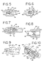
- FIG. 5 is a side cross sectional view of an excess flow valve showing the valve unsealed
- FIG. 6 is a side cross sectional view of the excess flow valve of FIG. 5 showing the valve sealed;
- FIG. 7 is a side cross sectional view of another excess flow valve with a ball and a spring
- FIG. 8 is a side cross sectional view of another excess flow valve with a cylinder sealing member and a spring
- FIG. 9 is a side cross sectional view of another excess flow valve with a ball and without a spring
- FIG. 10 is a side cross sectional view of another excess flow valve with a cylinder sealing member and magnets
- FIG. 11 is a side cross sectional view of one version of the invented fuel pressure relief valve
- FIG. 12 is a side cross sectional view of another version of the invented fuel pressure relief valve
- FIG. 13 is a side cross sectional view of another version of the invented fuel pressure relief valve
- FIG. 14 is a side cross sectional view of a parallel pressure relief valve and the invented fuel pressure relief valve integrated into a single valve assembly;
- FIG. 15 is a side cross sectional view of a parallel pressure relief valve and the invented fuel pressure relief valve integrated into a single valve assembly;
- FIG. 16 is a schematic of a parallel pressure relief valve and the invented fuel pressure relief valve integrated into a single valve assembly
- FIG. 17 is a schematic of a parallel pressure relief valve and the invented fuel pressure relief valve integrated into a single valve assembly.
- the fuel delivery system 10 is representative of typical fuel delivery systems used on automotive vehicles and includes a fuel tank 12 , a fuel pump 14 , a pump pressure relief valve 16 , a parallel pressure relief valve 18 , a fuel rail 20 , and a series of fuel injectors 22 .
- a typical parallel pressure relief valve consists of a 2.5 psi check valve and a 55 psi pressure relief valve.
- the fuel pump 14 supplies fuel to the fuel manifold, or fuel rail 20 , through the parallel pressure relief valve 18 .
- the fuel is then injected into the intake manifold (not shown) of the engine through the fuel injectors 22 .
- the fuel is maintained in a pressurized state in the fuel rail 20 by the parallel pressure relief valve 18 .
- the pressurized fuel in the fuel rail 20 can result in undesirable fuel leakage through the fuel injectors 22 , which results in evaporative emissions.
- fuel pressure buildup and leakage is exacerbated by diurnal temperature cycles.
- the fuel pressure is maintained at about 40 to 80 psi above the intake manifold pressure by the fuel pump 14 and the temperature of the fuel rail 20 typically stays at about 195° F. ( 40 ).
- the temperature (and thus the fuel rail pressure) increase slightly due to the fact that the cooling systems of the automotive vehicle are no longer running ( 42 ).
- the temperature of the fuel rail 20 then slowly cools and the pressure in the fuel rail 20 consequently falls along with the temperature decrease ( 44 ).
- FIG. 4 shows the pressure versus temperature characteristics of typical automotive fuels and the resulting liquid-vapor curves.
- the area above each liquid-vapor curve represents pressure-temperature combinations at which various fuels are in an entirely liquid state.
- the pressure and temperature of the system are said to lie “on the line,” i.e., are on the liquid-vapor curve.
- the pressure is determined by fuel temperature and fuel composition (i.e., the fuel type), assuming a single fuel temperature.
- the volume of the fuel begins to contract.
- the contracting fuel in the fuel rail 20 may draw up, or retrieve, additional fuel from either the fuel pump 14 or a fuel line 24 which terminates at the bottom of the fuel tank 12 .
- the contracting fuel may draw up fuel vapors into the fuel rail 20 instead.
- the fuel rail temperature reaches a minimum value (typically 65° F.) which usually occurs when the diurnal cycle is at a minimum temperature during the night ( 46 ).
- the fuel rail pressure reaches a corresponding minimum pressure (typically limited to ⁇ 2.5 psi by the check valve in the parallel pressure relief valve 18 ) ( 46 ).
- the temperature begins to increase again during the diurnal cycle of daytime warming.
- the pressure in the fuel rail 20 increases ( 48 ) until the temperature and pressure reach a maximum (typically 105° F.) which usually occurs in the middle of the day ( 50 ).
- the pressure increase that occurs during the diurnal cycle causes fuel to leak through the fuel injectors 22 , thereby contributing to evaporative emissions. This cycle is repeated each day until the automotive vehicle is restarted.
- the fuel pressure relief valve 26 includes an excess flow valve 28 and a back pressure relief valve 32 .
- the fuel pressure relief valve 26 is shown with the excess flow valve 28 connected to an input 36 that is in open communication with the fuel pump 14 and the fuel rail 20 .
- the back pressure relief valve 32 is then connected to the excess flow valve 28 in series, with the output 38 of the back pressure relief valve 32 being connected to a fuel line 39 that extends back to the fuel tank 12 .
- the fuel pressure relief valve 26 is preferably located in the fuel tank 12 of the automotive vehicle.
- the fuel pressure relief valve 26 may be used in numerous fuel systems, including return fuel systems (“RFS”), mechanical returnless fuel systems (“MRFS”), and electronic returnless fuel systems (“ERFS”), although ERFS systems are illustrated herein.
- back pressure relief valves sometimes referred to as back pressure regulators, open at pressures above a particular setting and seal for pressures below the setting.
- Back pressure relief valves have some flow sensitivity but typically regulate to a constant pressure regardless of flow characteristics.
- back pressure relief valves are constructed with an elastomeric diaphragm so that a large surface area exists against which the controlled pressure may act.
- pressure relief valves are typically of a more simple construction than back pressure relief valves.
- Pressure relief valves usually consist of a ball or poppet lifted off of a seat. Thus, pressure relief valves are more sensitive to flow characteristics. For this reason, once a pressure relief valve is unsealed, it can stay off the seat until the flow rate is low.
- an orifice is often placed in series with the pressure relief valve.
- these valves often have large hysteresis. This means that they unseal at the set pressure but reseal at a pressure at least a few psi below the set pressure. Unless special care is taken to eliminate this hysteresis, the valve will not be suitable for some tasks.
- the excess flow valve 28 includes a spring 29 that biases a ball 30 away from a seat 31 .
- the excess flow valve 28 seals against the seat 31 when the fuel flow exceeds about 5 cc/sec and remains sealed until the input pressure drops below about 2 psi.
- the back pressure relief valve 32 includes a spring 33 that biases a ball 34 towards a seat 35 .
- the back pressure relief valve 32 remains sealed when the input pressure is less than about 3 psi and unseals when the input pressure exceeds about 3 psi.
- the fuel pressure relief valve 26 minimizes fuel pressure buildup and resulting fuel leakage and evaporative emissions when the automotive vehicle is not operating.
- the excess flow valve 28 will experience a flow greater than the preferred 5 cc/sec shut-off flow.
- the excess flow valve 28 will then seal and stay sealed while the automotive vehicle operates. Therefore, throughout operation of the vehicle, the fuel flow to the back pressure relief valve 32 will be prevented by the excess flow valve 28 .
- the parallel pressure relief valve 18 maintains pressure in the fuel rail 20 .
- the excess flow valve 28 unseals when the pressure drops below the preferred 2 psi release pressure.
- the excess flow valve 28 then remains unsealed throughout the remaining time that the automotive vehicle is not operating.
- FIG. 2 now when the ambient temperature increases during the next diurnal cycle, fuel will be released through the back pressure relief valve 32 whenever the fuel rail pressure exceeds the preferred 3 psi release pressure.
- the fuel rail pressure remains at a lower pressure throughout subsequent diurnal cycles (limited to about 3 psi by the back pressure relief valve 32 ) ( 47 ), while at the same time keeping the fuel rail 20 mostly filled with liquid fuel.
- FIG. 5 shows an excess flow valve 50 in an open position, in which the sealing member is a vane 52 .
- the excess flow valve 50 also includes a spring 54 that biases the vane 52 away from the seat 56 .
- FIG. 5 a small amount of flow is shown passing from the input 58 to the output 60 of the valve 50 without closing the valve 50 .
- FIG. 6 the same valve 50 is shown with the vane 52 sealed against the seat 56 as a result of the flow exceeding the shut-off flow rate.
- FIG. 7 another excess flow valve 64 is shown.
- a spring 66 biases a ball 68 away from the seat 70 .
- a filter member 72 with a stop portion 73 is installed in the input 74 .
- the stop portion 23 thereby retains the ball 68 within the valve 64 .
- the ball 68 seals against the seat 70 and prevents flow through the output 76 .
- FIG. 8 another excess flow valve 80 is shown which is similar to the version in FIG. 7 .
- the input 82 , output 84 , spring 86 and seat 87 are similar to those shown in FIG. 7 .
- the sealing member is a cylinder-shaped member 88 , and the cylinder-shaped member 88 is retained with a roll pin 90 .
- FIG. 9 another excess flow valve 94 is shown with an input 96 and an output 98 .
- no spring is used to bias the ball 100 away from the seat 102 .
- a spacer 104 traps the ball 100 between the spacer 104 and the seat 102 .
- FIG. 10 another excess flow valve 106 is shown.
- attracting magnets 108 , 110 are used to unseal the valve 106 .
- the adjustable stationary magnet 108 is mounted in an endplug 112 .
- the endplug 112 is sealed with the body 114 to prevent leakage with o-rings 115 and a cover 116 .
- the position of the stationary magnet 108 may then be adjusted with an adjusting screw 118 .
- the moveable piston 120 includes a magnet 110 , which is attracted towards the stationary magnet 108 .
- An o-ring 122 is also included at the output 124 to seal the piston 120 in the closed position (as shown).
- fuel flows through the input 126 and creates a pressure differential across the piston 120 as the fuel flows to the output 124 .
- the pressure differential becomes high enough, the piston 120 moves towards the output 124 and restricts additional flow between the input 126 and the output 124 .
- the magnets 108 , 110 pull the piston 120 away from the output 124 , thus unsealing the valve 106 .
- FIG. 11 a version of the fuel pressure relief valve 130 is shown, which may be more cost effective to manufacture since parts of the excess flow valve 28 and the back pressure relief valve 32 have been combined.
- the body 132 of the valve 130 is made from acetal and includes an input 132 and an output 134 .
- a single ball 136 is used in the fuel pressure relief valve 130 and acts like a joined sealing member.
- a spring 138 is installed between the ball 136 and the output 134 .
- the ball 136 is then trapped between two seats formed from viton o-rings 140 , 142 .
- Cylindrical acetal spacers 144 are pressed into the input 132 to position the o-rings 140 , 142 .
- FIG. 12 another version of the fuel pressure relief valve 150 is shown. Like the version shown in FIG. 12 , this version may be more cost effective since certain parts have been combined or eliminated.
- the body is made from two portions 152 , 154 that are welded together with sonic welding.
- the first portion 152 includes the input 156
- the second portion 154 includes the output 158 .
- a single o-ring 160 is trapped between the two portions 152 , 154 of the body, thereby acting like joined seats.
- a poppet 162 with two joined vane surfaces 164 , 166 is also trapped by the o-ring 160 , which is positioned between the two vane surfaces 164 , 166 .
- a spring 168 is then installed between the poppet 162 and the output 158 .
- valve 150 acts like the back pressure relief valve 32 previously described.
- the output poppet vane 164 moves away from the o-ring 160 and lets a small amount of fuel pass through the valve 150 to the output 158 .
- FIG. 13 another version of the fuel pressure relief valve 180 is shown. Like the versions shown in FIGS. 11 and 12 , this version may be more cost effective since certain parts have been combined or eliminated.
- the body is made from two portions 182 , 184 .
- the first portion 182 includes the input 186 and an inner bore 188 .
- the second portion 184 includes the output 190 and an outer bore 192 sized to fit within the inner bore 188 of the first portion 182 .
- the first and second portions 182 , 184 are affixed to each other through a press fit, welding, gluing or the like.
- a single ball 194 is used in the fuel pressure relief valve 180 and acts like a joined sealing member.
- the ball 194 is preferably made of viton.
- a spring 196 is installed between the ball 194 and the output 190 .
- the ball 194 is trapped between one seat 198 formed in the first portion 182 and another seat 200 formed in the second portion 184 .
- FIGS. 14–17 various versions of a single valve assembly are shown with the fuel pressure relief valve 26 integrated with the parallel pressure relief valve 18 .
- the integrated valve assembly 170 is shown with a parallel pressure relief valve 18 on the left side of the valve assembly 170 and the fuel pressure relief valve 26 on the right side of the valve assembly 170 .
- the integrated valve assembly 174 shown in FIG. 16 is similar to this version).
- the fuel pressure relief valve 26 is connected to the pump 14 on one end and the fuel rail 20 on the other end.
- the excess flow valve 28 closes when the automotive vehicle is turned off and the pump 14 de-energizes.
- an integrated valve assembly 172 is shown using the fuel pressure relief valve 180 shown in FIG. 13 and described above.
- FIG. 17 the integrated valve assembly 176 is shown with the fuel pressure relief valve 26 connected between the fuel rail 20 and the return fuel line 39 .
- the excess fuel valve 28 closes when the automotive vehicle is turned on and the pump 14 is energized.
- FIG. 17 represents the same system schematic as shown in FIGS. 1 and 2 .
Landscapes
- Engineering & Computer Science (AREA)
- Chemical & Material Sciences (AREA)
- Combustion & Propulsion (AREA)
- Mechanical Engineering (AREA)
- General Engineering & Computer Science (AREA)
- Fuel-Injection Apparatus (AREA)
Abstract
Description
Claims (22)
Priority Applications (3)
| Application Number | Priority Date | Filing Date | Title |
|---|---|---|---|
| US10/655,863 US6988488B2 (en) | 2003-04-15 | 2003-09-05 | Fuel pressure relief valve |
| GB0403418A GB2400641B (en) | 2003-04-15 | 2004-02-17 | Fuel pressure relief valve |
| DE102004018888A DE102004018888A1 (en) | 2003-04-15 | 2004-04-15 | Fuel pressure limiting valve |
Applications Claiming Priority (2)
| Application Number | Priority Date | Filing Date | Title |
|---|---|---|---|
| US46297403P | 2003-04-15 | 2003-04-15 | |
| US10/655,863 US6988488B2 (en) | 2003-04-15 | 2003-09-05 | Fuel pressure relief valve |
Publications (2)
| Publication Number | Publication Date |
|---|---|
| US20040206338A1 US20040206338A1 (en) | 2004-10-21 |
| US6988488B2 true US6988488B2 (en) | 2006-01-24 |
Family
ID=32045454
Family Applications (1)
| Application Number | Title | Priority Date | Filing Date |
|---|---|---|---|
| US10/655,863 Expired - Fee Related US6988488B2 (en) | 2003-04-15 | 2003-09-05 | Fuel pressure relief valve |
Country Status (3)
| Country | Link |
|---|---|
| US (1) | US6988488B2 (en) |
| DE (1) | DE102004018888A1 (en) |
| GB (1) | GB2400641B (en) |
Cited By (23)
| Publication number | Priority date | Publication date | Assignee | Title |
|---|---|---|---|---|
| US20060000448A1 (en) * | 2004-06-30 | 2006-01-05 | C.R.F. Societa Consortile Per Azioni | Device for regulating pressure/flow in an internal combustion engine fuel injection system |
| US20060137746A1 (en) * | 2004-12-24 | 2006-06-29 | Katsuya Maita | Pressure regulation apparatus |
| US20060225711A1 (en) * | 2003-08-18 | 2006-10-12 | Peter Schelhas | Device for conveying fuel out of a tank and to a combustion engine |
| US20070095330A1 (en) * | 2005-10-31 | 2007-05-03 | Burke David H | Fuel line check valve system and method |
| US20070144489A1 (en) * | 2004-10-24 | 2007-06-28 | Kjell Fischer | Injector Leakage Limitation |
| US20080149069A1 (en) * | 2004-06-04 | 2008-06-26 | Robert Bosch Gmbh | Fuel Injection System |
| US7441545B1 (en) | 2007-12-12 | 2008-10-28 | Robert Bosch Gmbh | Fuel pressure relief valve |
| US7444990B1 (en) | 2007-12-12 | 2008-11-04 | Robert Bosch Gmbh | Fuel line check valve |
| US7448361B1 (en) | 2007-10-23 | 2008-11-11 | Ford Global Technologies, Llc | Direct injection fuel system utilizing water hammer effect |
| US20090095259A1 (en) * | 2007-10-12 | 2009-04-16 | Ford Global Technologies, Llc | Fuel System for Improved Engine Starting |
| US20090107461A1 (en) * | 2007-10-26 | 2009-04-30 | Ford Global Technologies, Llc | Direct Injection Fuel System with Reservoir |
| US20110011371A1 (en) * | 2008-02-29 | 2011-01-20 | Giancarlo Magrone | Pump unit for a fuel injection system of an internal combustion engine |
| US20110114064A1 (en) * | 2007-11-16 | 2011-05-19 | Toyota Jidosha Kabushiki Kaisha | High-pressure fuel supply apparatus for internal combustion engine |
| US20110168133A1 (en) * | 2010-05-28 | 2011-07-14 | Ford Global Technologies, Llc | Approach for controlling fuel flow with alternative fuels |
| US20120073546A1 (en) * | 2010-09-24 | 2012-03-29 | Denso Corporation | Cleaning a pressure control function valve |
| US9546628B2 (en) | 2014-12-02 | 2017-01-17 | Ford Global Technologies, Llc | Identifying fuel system degradation |
| US9726105B2 (en) | 2014-12-02 | 2017-08-08 | Ford Global Technologies, Llc | Systems and methods for sensing fuel vapor pressure |
| US9771909B2 (en) | 2014-12-02 | 2017-09-26 | Ford Global Technologies, Llc | Method for lift pump control |
| US10094319B2 (en) | 2014-12-02 | 2018-10-09 | Ford Global Technologies, Llc | Optimizing intermittent fuel pump control |
| US20220023019A1 (en) * | 2020-07-22 | 2022-01-27 | Water Pik, Inc. | Bypass flow assembly of an oral irrigator |
| US11261836B1 (en) * | 2021-03-09 | 2022-03-01 | Ford Global Technologies, Llc | Fuel system check valve |
| US11300080B2 (en) * | 2019-05-17 | 2022-04-12 | Dayco Ip Holdings, Llc | Fuel tank protector valve and engine systems having same |
| US11754028B2 (en) | 2021-06-23 | 2023-09-12 | Ford Global Technologies, Llc | Fuel system diaphragm valve |
Families Citing this family (10)
| Publication number | Priority date | Publication date | Assignee | Title |
|---|---|---|---|---|
| DE102005003592A1 (en) * | 2005-01-26 | 2006-08-03 | Daimlerchrysler Ag | Fuel supply device e.g. for supplying internal combustion engine with fuel, has electrically driven fuel pump which delivers fuel from fuel reservoir via fuel filter to internal combustion engine |
| US7267108B2 (en) * | 2005-04-18 | 2007-09-11 | Ford Global Technologies, Llc | Fuel system pressure relief valve with integral accumulator |
| WO2007064328A1 (en) * | 2005-11-30 | 2007-06-07 | Carrier Corporation | Pulse width modulated system with pressure regulating valve |
| JP4579997B2 (en) | 2008-03-25 | 2010-11-10 | 株式会社日本自動車部品総合研究所 | A pressure regulating check valve and a fuel injection device including the same. |
| DE102008040924A1 (en) | 2008-08-01 | 2010-02-04 | Robert Bosch Gmbh | Pressure limiting valve for fuel supplying system, has valve unit, which is movably arranged in valve area of valve housing between two final positions |
| US8443785B2 (en) * | 2010-09-10 | 2013-05-21 | GM Global Technology Operations LLC | Liquefied petroleum gas (LPG) pump control systems and methods |
| DE102011089972A1 (en) * | 2011-12-27 | 2013-06-27 | Robert Bosch Gmbh | Fuel overflow valve for a fuel injector and fuel injector with fuel spill valve |
| KR101349509B1 (en) * | 2012-05-24 | 2014-01-09 | 현대자동차주식회사 | LPI Fuel System and Return Fuel Minimum Method thereof |
| DE102012224004A1 (en) * | 2012-12-20 | 2014-06-26 | Robert Bosch Gmbh | High-pressure injection |
| US9650982B2 (en) | 2015-06-02 | 2017-05-16 | GM Global Technology Operations LLC | Liquefied petroleum gas butane composition determination systems and methods |
Citations (29)
| Publication number | Priority date | Publication date | Assignee | Title |
|---|---|---|---|---|
| US2090781A (en) | 1933-07-12 | 1937-08-24 | Atlas Diesel Ab | Fuel pump for internal combustion engines |
| US2234924A (en) | 1938-05-25 | 1941-03-11 | Timken Roller Bearing Co | Fuel pump |
| US2915335A (en) * | 1956-05-22 | 1959-12-01 | James H Barnes | Tire trim member and securing means therefor |
| GB1179357A (en) | 1967-08-19 | 1970-01-28 | Bosch Gmbh Robert | Improvements in Fuel Injection Systems for Internal Combustion Engines |
| US3742926A (en) * | 1970-08-27 | 1973-07-03 | Cav Ltd | Delivery valves |
| US4556077A (en) | 1983-12-20 | 1985-12-03 | Allied Corporation | Switching valve for a fuel supply system |
| US4648369A (en) | 1984-05-10 | 1987-03-10 | Robert Bosch Gmbh | Pressure valve |
| US4709680A (en) * | 1985-07-02 | 1987-12-01 | Weber S.P.A. Azienda Altecna | Device for controlling fuel injection apparatus in diesel engines |
| US4938254A (en) | 1989-09-21 | 1990-07-03 | Borg-Warner Automotive Electronic & Mechanical Systems | Over-pressure relief valve |
| US4989590A (en) * | 1986-06-17 | 1991-02-05 | Teledyne Industries, Inc. | Irrigation appliance |
| US5044389A (en) | 1990-08-28 | 1991-09-03 | Borg-Warner Automotive, Inc. | High volume fuel vapor release valve |
| US5183087A (en) | 1991-06-10 | 1993-02-02 | Borg-Warner Automotive Electronic & Mechanical Systems Corporation | Refueling vapor recovery system |
| US5244022A (en) | 1992-09-25 | 1993-09-14 | Borg-Warner Automotive, Inc. | Fuel flow activated fuel vapor control apparatus |
| US5339785A (en) * | 1992-06-29 | 1994-08-23 | Ford Motor Company | Automotive fuel supply apparatus and control valve |
| US5361742A (en) * | 1993-02-08 | 1994-11-08 | Walbro Corporation | Fuel pump manifold |
| US5365906A (en) * | 1993-12-20 | 1994-11-22 | Chrysler Corporation | Fluid flow check valve for fuel system |
| US5413137A (en) | 1994-02-14 | 1995-05-09 | Borg-Warner Automotive, Inc. | Fuel vapor vent assembly with liquid trap |
| US5477829A (en) * | 1994-08-08 | 1995-12-26 | Ford Motor Company | Automotive returnless fuel system pressure valve |
| US5572974A (en) | 1995-02-21 | 1996-11-12 | Siemens Automotive Corporation | Combined start bypass and safety pressure relief valve for a fuel system |
| US5623910A (en) | 1994-11-30 | 1997-04-29 | Walbro Corporation | Check and vent valve assembly |
| US5638786A (en) | 1996-08-16 | 1997-06-17 | Ford Motor Company | Self-cleaning air filter for a fuel vapor recovery system |
| US5749345A (en) | 1995-11-02 | 1998-05-12 | Bayerische Motoren Werke Aktiengesellschaft | Fuel system |
| US20010025629A1 (en) | 2000-03-29 | 2001-10-04 | Eurocopter Deutschland Gmbh | Valve arrangement in a feed line to deliver fuel from a tank to an internal combustion engine |
| US6305413B1 (en) | 1999-02-19 | 2001-10-23 | Ultradent Products, Inc. | Mixing adaptor system |
| US6488006B2 (en) | 2001-03-22 | 2002-12-03 | Visteon Global Technologies, Inc. | Electronic throttle idle speed control system |
| US6502557B2 (en) | 2000-03-17 | 2003-01-07 | Denso Corporation | Check valve for engine fuel supply system |
| US6553817B1 (en) | 1999-11-18 | 2003-04-29 | Visteon Global Tech., Inc. | Method and apparatus for monitoring a catalytic converter |
| US6575427B1 (en) | 1999-11-10 | 2003-06-10 | Visteon Global Technologies, Inc. | Electronic throttle control mechanism with reduced friction and wear |
| US6622701B2 (en) * | 2000-11-27 | 2003-09-23 | Denso Corporation | Accumulator fuel injection system designed to avoid failure of relief valve caused by pressure pulsation |
-
2003
- 2003-09-05 US US10/655,863 patent/US6988488B2/en not_active Expired - Fee Related
-
2004
- 2004-02-17 GB GB0403418A patent/GB2400641B/en not_active Expired - Fee Related
- 2004-04-15 DE DE102004018888A patent/DE102004018888A1/en not_active Ceased
Patent Citations (29)
| Publication number | Priority date | Publication date | Assignee | Title |
|---|---|---|---|---|
| US2090781A (en) | 1933-07-12 | 1937-08-24 | Atlas Diesel Ab | Fuel pump for internal combustion engines |
| US2234924A (en) | 1938-05-25 | 1941-03-11 | Timken Roller Bearing Co | Fuel pump |
| US2915335A (en) * | 1956-05-22 | 1959-12-01 | James H Barnes | Tire trim member and securing means therefor |
| GB1179357A (en) | 1967-08-19 | 1970-01-28 | Bosch Gmbh Robert | Improvements in Fuel Injection Systems for Internal Combustion Engines |
| US3742926A (en) * | 1970-08-27 | 1973-07-03 | Cav Ltd | Delivery valves |
| US4556077A (en) | 1983-12-20 | 1985-12-03 | Allied Corporation | Switching valve for a fuel supply system |
| US4648369A (en) | 1984-05-10 | 1987-03-10 | Robert Bosch Gmbh | Pressure valve |
| US4709680A (en) * | 1985-07-02 | 1987-12-01 | Weber S.P.A. Azienda Altecna | Device for controlling fuel injection apparatus in diesel engines |
| US4989590A (en) * | 1986-06-17 | 1991-02-05 | Teledyne Industries, Inc. | Irrigation appliance |
| US4938254A (en) | 1989-09-21 | 1990-07-03 | Borg-Warner Automotive Electronic & Mechanical Systems | Over-pressure relief valve |
| US5044389A (en) | 1990-08-28 | 1991-09-03 | Borg-Warner Automotive, Inc. | High volume fuel vapor release valve |
| US5183087A (en) | 1991-06-10 | 1993-02-02 | Borg-Warner Automotive Electronic & Mechanical Systems Corporation | Refueling vapor recovery system |
| US5339785A (en) * | 1992-06-29 | 1994-08-23 | Ford Motor Company | Automotive fuel supply apparatus and control valve |
| US5244022A (en) | 1992-09-25 | 1993-09-14 | Borg-Warner Automotive, Inc. | Fuel flow activated fuel vapor control apparatus |
| US5361742A (en) * | 1993-02-08 | 1994-11-08 | Walbro Corporation | Fuel pump manifold |
| US5365906A (en) * | 1993-12-20 | 1994-11-22 | Chrysler Corporation | Fluid flow check valve for fuel system |
| US5413137A (en) | 1994-02-14 | 1995-05-09 | Borg-Warner Automotive, Inc. | Fuel vapor vent assembly with liquid trap |
| US5477829A (en) * | 1994-08-08 | 1995-12-26 | Ford Motor Company | Automotive returnless fuel system pressure valve |
| US5623910A (en) | 1994-11-30 | 1997-04-29 | Walbro Corporation | Check and vent valve assembly |
| US5572974A (en) | 1995-02-21 | 1996-11-12 | Siemens Automotive Corporation | Combined start bypass and safety pressure relief valve for a fuel system |
| US5749345A (en) | 1995-11-02 | 1998-05-12 | Bayerische Motoren Werke Aktiengesellschaft | Fuel system |
| US5638786A (en) | 1996-08-16 | 1997-06-17 | Ford Motor Company | Self-cleaning air filter for a fuel vapor recovery system |
| US6305413B1 (en) | 1999-02-19 | 2001-10-23 | Ultradent Products, Inc. | Mixing adaptor system |
| US6575427B1 (en) | 1999-11-10 | 2003-06-10 | Visteon Global Technologies, Inc. | Electronic throttle control mechanism with reduced friction and wear |
| US6553817B1 (en) | 1999-11-18 | 2003-04-29 | Visteon Global Tech., Inc. | Method and apparatus for monitoring a catalytic converter |
| US6502557B2 (en) | 2000-03-17 | 2003-01-07 | Denso Corporation | Check valve for engine fuel supply system |
| US20010025629A1 (en) | 2000-03-29 | 2001-10-04 | Eurocopter Deutschland Gmbh | Valve arrangement in a feed line to deliver fuel from a tank to an internal combustion engine |
| US6622701B2 (en) * | 2000-11-27 | 2003-09-23 | Denso Corporation | Accumulator fuel injection system designed to avoid failure of relief valve caused by pressure pulsation |
| US6488006B2 (en) | 2001-03-22 | 2002-12-03 | Visteon Global Technologies, Inc. | Electronic throttle idle speed control system |
Cited By (37)
| Publication number | Priority date | Publication date | Assignee | Title |
|---|---|---|---|---|
| US20060225711A1 (en) * | 2003-08-18 | 2006-10-12 | Peter Schelhas | Device for conveying fuel out of a tank and to a combustion engine |
| US7278402B2 (en) * | 2003-08-18 | 2007-10-09 | Robert Bosch Gmbh | Device for conveying fuel out of a tank and to a combustion engine |
| US20080149069A1 (en) * | 2004-06-04 | 2008-06-26 | Robert Bosch Gmbh | Fuel Injection System |
| US7574994B2 (en) * | 2004-06-04 | 2009-08-18 | Robert Bosch Gmbh | Fuel injection system |
| US7891338B2 (en) * | 2004-06-30 | 2011-02-22 | C.R.F. Societa Consortile Per Azioni | Device for regulating pressure/flow in an internal combustion engine fuel injection system |
| US20060000448A1 (en) * | 2004-06-30 | 2006-01-05 | C.R.F. Societa Consortile Per Azioni | Device for regulating pressure/flow in an internal combustion engine fuel injection system |
| US20070144489A1 (en) * | 2004-10-24 | 2007-06-28 | Kjell Fischer | Injector Leakage Limitation |
| US7290534B2 (en) * | 2004-10-26 | 2007-11-06 | Ford Global Technologies, Llc | Injector leakage limitation |
| US20060137746A1 (en) * | 2004-12-24 | 2006-06-29 | Katsuya Maita | Pressure regulation apparatus |
| US7757673B2 (en) * | 2005-10-31 | 2010-07-20 | Delphi Technologies, Inc. | Three position fuel line check valve for relief of diurnal pressure |
| US7246607B2 (en) * | 2005-10-31 | 2007-07-24 | Delphi Technologies, Inc. | Three position fuel line check valve for relief of diurnal pressure |
| US7444995B2 (en) | 2005-10-31 | 2008-11-04 | Delphi Technologies, Inc. | Fuel line check valve system for relief of diurnal pressure |
| US20090007889A1 (en) * | 2005-10-31 | 2009-01-08 | Delphi Technologies, Inc. | Three position fuel line check valve for relief of diurnal pressure |
| US20070095330A1 (en) * | 2005-10-31 | 2007-05-03 | Burke David H | Fuel line check valve system and method |
| US20070221179A1 (en) * | 2005-10-31 | 2007-09-27 | Delphi Technologies, Inc. | Fuel line check valve system and method |
| US8833343B2 (en) | 2007-10-12 | 2014-09-16 | Ford Global Technologies, Llc | Fuel system for improved engine starting |
| US20090095259A1 (en) * | 2007-10-12 | 2009-04-16 | Ford Global Technologies, Llc | Fuel System for Improved Engine Starting |
| US7448361B1 (en) | 2007-10-23 | 2008-11-11 | Ford Global Technologies, Llc | Direct injection fuel system utilizing water hammer effect |
| US7966984B2 (en) | 2007-10-26 | 2011-06-28 | Ford Global Technologies, Llc | Direct injection fuel system with reservoir |
| US20090107461A1 (en) * | 2007-10-26 | 2009-04-30 | Ford Global Technologies, Llc | Direct Injection Fuel System with Reservoir |
| US20110114064A1 (en) * | 2007-11-16 | 2011-05-19 | Toyota Jidosha Kabushiki Kaisha | High-pressure fuel supply apparatus for internal combustion engine |
| US9169815B2 (en) * | 2007-11-16 | 2015-10-27 | Toyota Jidosha Kabushiki Kaisha | High-pressure fuel supply apparatus for internal combustion engine |
| US7444990B1 (en) | 2007-12-12 | 2008-11-04 | Robert Bosch Gmbh | Fuel line check valve |
| US7441545B1 (en) | 2007-12-12 | 2008-10-28 | Robert Bosch Gmbh | Fuel pressure relief valve |
| US20110011371A1 (en) * | 2008-02-29 | 2011-01-20 | Giancarlo Magrone | Pump unit for a fuel injection system of an internal combustion engine |
| US20110168133A1 (en) * | 2010-05-28 | 2011-07-14 | Ford Global Technologies, Llc | Approach for controlling fuel flow with alternative fuels |
| US8622047B2 (en) * | 2010-09-24 | 2014-01-07 | Denso Corporation | Cleaning a pressure control function valve |
| US20120073546A1 (en) * | 2010-09-24 | 2012-03-29 | Denso Corporation | Cleaning a pressure control function valve |
| US9546628B2 (en) | 2014-12-02 | 2017-01-17 | Ford Global Technologies, Llc | Identifying fuel system degradation |
| US9726105B2 (en) | 2014-12-02 | 2017-08-08 | Ford Global Technologies, Llc | Systems and methods for sensing fuel vapor pressure |
| US9771909B2 (en) | 2014-12-02 | 2017-09-26 | Ford Global Technologies, Llc | Method for lift pump control |
| US10094319B2 (en) | 2014-12-02 | 2018-10-09 | Ford Global Technologies, Llc | Optimizing intermittent fuel pump control |
| US11300080B2 (en) * | 2019-05-17 | 2022-04-12 | Dayco Ip Holdings, Llc | Fuel tank protector valve and engine systems having same |
| US20220023019A1 (en) * | 2020-07-22 | 2022-01-27 | Water Pik, Inc. | Bypass flow assembly of an oral irrigator |
| US12263053B2 (en) * | 2020-07-22 | 2025-04-01 | Water Pik, Inc. | Bypass flow assembly of an oral irrigator |
| US11261836B1 (en) * | 2021-03-09 | 2022-03-01 | Ford Global Technologies, Llc | Fuel system check valve |
| US11754028B2 (en) | 2021-06-23 | 2023-09-12 | Ford Global Technologies, Llc | Fuel system diaphragm valve |
Also Published As
| Publication number | Publication date |
|---|---|
| GB2400641B (en) | 2005-03-23 |
| US20040206338A1 (en) | 2004-10-21 |
| DE102004018888A1 (en) | 2004-11-11 |
| GB0403418D0 (en) | 2004-03-24 |
| GB2400641A (en) | 2004-10-20 |
Similar Documents
| Publication | Publication Date | Title |
|---|---|---|
| US6988488B2 (en) | Fuel pressure relief valve | |
| US7107971B2 (en) | Isolation valve useful in fuel tank emission control systems | |
| US5727529A (en) | Pressure control valve for a fuel system | |
| US7513240B2 (en) | High pressure fuel pump provided with damper | |
| US5673670A (en) | Returnless fuel delivery system | |
| US8297941B2 (en) | Fuel pump | |
| US7444990B1 (en) | Fuel line check valve | |
| US5083546A (en) | Two-stage high flow purge valve | |
| JP2747428B2 (en) | Demand fuel pressure regulator | |
| US6092545A (en) | Magnetic actuated valve | |
| US9243588B2 (en) | Variable pressure gaseous fuel regulator | |
| US9359963B2 (en) | Gaseous fuel rail depressurization during inactive injector conditions | |
| JPH08121290A (en) | No-return fuel device with demand fuel pressure regulator | |
| US5469886A (en) | Solenoid valve | |
| CN100402833C (en) | Fuel system shut-off valve | |
| US7007708B2 (en) | Flow control valve | |
| US7178512B1 (en) | Fuel system for a marine vessel with a gaseous purge fuel container | |
| US6792918B1 (en) | Vacuum relief modular reservoir assembly | |
| CN110469430A (en) | Valve assembly for regulating gas pressure and fuel system with valve assembly | |
| US6189517B1 (en) | Internal combustion engine with low viscosity fuel system | |
| EP1596056A1 (en) | Gas feeding system for an internal combustion engine, having a pressure reducing valve connected to the intake manifold | |
| JP2002533614A (en) | Fuel injection device | |
| US6092500A (en) | Fuel delivery device | |
| JP2010038139A (en) | Accumulating fuel injection device | |
| US11773991B2 (en) | Fuel demand valve with anti-siphon and pressure protection |
Legal Events
| Date | Code | Title | Description |
|---|---|---|---|
| AS | Assignment |
Owner name: VISTEON GLOBAL TECHNOLOGIES, INC., ILLINOIS Free format text: ASSIGNMENT OF ASSIGNORS INTEREST;ASSIGNORS:PURSIFULL, ROSS D.;GIMBY, DAVID R.;REEL/FRAME:014472/0063;SIGNING DATES FROM 20030822 TO 20030826 |
|
| AS | Assignment |
Owner name: AUTOMOTIVE COMPONENTS HOLDINGS, LLC, MICHIGAN Free format text: ASSIGNMENT OF ASSIGNORS INTEREST;ASSIGNOR:VISTEON GLOBAL TECHNOLOGIES, INC.;REEL/FRAME:016835/0448 Effective date: 20051129 |
|
| AS | Assignment |
Owner name: FORD MOTOR COMPANY, MICHIGAN Free format text: ASSIGNMENT OF ASSIGNORS INTEREST;ASSIGNOR:AUTOMOTIVE COMPONENTS HOLDINGS, LLC;REEL/FRAME:017164/0694 Effective date: 20060214 |
|
| AS | Assignment |
Owner name: FORD GLOBAL TECHNOLOGIES, LLC, MICHIGAN Free format text: ASSIGNMENT OF ASSIGNORS INTEREST;ASSIGNOR:FORD MOTOR COMPANY;REEL/FRAME:022562/0494 Effective date: 20090414 Owner name: FORD GLOBAL TECHNOLOGIES, LLC,MICHIGAN Free format text: ASSIGNMENT OF ASSIGNORS INTEREST;ASSIGNOR:FORD MOTOR COMPANY;REEL/FRAME:022562/0494 Effective date: 20090414 |
|
| FPAY | Fee payment |
Year of fee payment: 4 |
|
| REMI | Maintenance fee reminder mailed | ||
| LAPS | Lapse for failure to pay maintenance fees | ||
| LAPS | Lapse for failure to pay maintenance fees |
Free format text: PATENT EXPIRED FOR FAILURE TO PAY MAINTENANCE FEES (ORIGINAL EVENT CODE: EXP.) |
|
| STCH | Information on status: patent discontinuation |
Free format text: PATENT EXPIRED DUE TO NONPAYMENT OF MAINTENANCE FEES UNDER 37 CFR 1.362 |
|
| FP | Lapsed due to failure to pay maintenance fee |
Effective date: 20140124 |
|
| STCH | Information on status: patent discontinuation |
Free format text: PATENT EXPIRED DUE TO NONPAYMENT OF MAINTENANCE FEES UNDER 37 CFR 1.362 |