US6976662B2 - Ceiling grid sign hanger - Google Patents
Ceiling grid sign hanger Download PDFInfo
- Publication number
- US6976662B2 US6976662B2 US10/083,251 US8325101A US6976662B2 US 6976662 B2 US6976662 B2 US 6976662B2 US 8325101 A US8325101 A US 8325101A US 6976662 B2 US6976662 B2 US 6976662B2
- Authority
- US
- United States
- Prior art keywords
- ceiling grid
- support body
- hanger
- flange
- longitudinal axis
- Prior art date
- Legal status (The legal status is an assumption and is not a legal conclusion. Google has not performed a legal analysis and makes no representation as to the accuracy of the status listed.)
- Expired - Lifetime, expires
Links
- 238000011900 installation process Methods 0.000 claims description 16
- 230000001965 increasing effect Effects 0.000 claims description 12
- 230000002441 reversible effect Effects 0.000 claims description 3
- 230000002708 enhancing effect Effects 0.000 claims description 2
- 238000009434 installation Methods 0.000 description 19
- 229920001169 thermoplastic Polymers 0.000 description 7
- 239000004416 thermosoftening plastic Substances 0.000 description 7
- 239000000463 material Substances 0.000 description 6
- 238000000034 method Methods 0.000 description 6
- XECAHXYUAAWDEL-UHFFFAOYSA-N acrylonitrile butadiene styrene Chemical compound C=CC=C.C=CC#N.C=CC1=CC=CC=C1 XECAHXYUAAWDEL-UHFFFAOYSA-N 0.000 description 4
- 239000004676 acrylonitrile butadiene styrene Substances 0.000 description 4
- 229920000122 acrylonitrile butadiene styrene Polymers 0.000 description 4
- 238000010276 construction Methods 0.000 description 4
- 230000014759 maintenance of location Effects 0.000 description 4
- 238000000465 moulding Methods 0.000 description 3
- 239000000725 suspension Substances 0.000 description 3
- 239000004677 Nylon Substances 0.000 description 2
- 230000004075 alteration Effects 0.000 description 2
- 238000005452 bending Methods 0.000 description 2
- 239000012141 concentrate Substances 0.000 description 2
- 230000000670 limiting effect Effects 0.000 description 2
- 238000012986 modification Methods 0.000 description 2
- 230000004048 modification Effects 0.000 description 2
- 238000003032 molecular docking Methods 0.000 description 2
- 229920001778 nylon Polymers 0.000 description 2
- 230000036961 partial effect Effects 0.000 description 2
- 230000002829 reductive effect Effects 0.000 description 2
- 239000011800 void material Substances 0.000 description 2
- 229910000639 Spring steel Inorganic materials 0.000 description 1
- 239000000853 adhesive Substances 0.000 description 1
- 230000001070 adhesive effect Effects 0.000 description 1
- 230000000712 assembly Effects 0.000 description 1
- 238000000429 assembly Methods 0.000 description 1
- 230000009286 beneficial effect Effects 0.000 description 1
- 230000006835 compression Effects 0.000 description 1
- 238000007906 compression Methods 0.000 description 1
- 230000000368 destabilizing effect Effects 0.000 description 1
- 238000006073 displacement reaction Methods 0.000 description 1
- 230000000694 effects Effects 0.000 description 1
- -1 for example Substances 0.000 description 1
- 238000012423 maintenance Methods 0.000 description 1
- 238000004519 manufacturing process Methods 0.000 description 1
- 230000013011 mating Effects 0.000 description 1
- 239000002184 metal Substances 0.000 description 1
- 239000003973 paint Substances 0.000 description 1
- 239000011253 protective coating Substances 0.000 description 1
- 238000004080 punching Methods 0.000 description 1
- 239000012858 resilient material Substances 0.000 description 1
- 238000004904 shortening Methods 0.000 description 1
- 239000003381 stabilizer Substances 0.000 description 1
Images


Classifications
-
- G—PHYSICS
- G09—EDUCATION; CRYPTOGRAPHY; DISPLAY; ADVERTISING; SEALS
- G09F—DISPLAYING; ADVERTISING; SIGNS; LABELS OR NAME-PLATES; SEALS
- G09F7/00—Signs, name or number plates, letters, numerals, or symbols; Panels or boards
- G09F7/18—Means for attaching signs, plates, panels, or boards to a supporting structure
-
- E—FIXED CONSTRUCTIONS
- E04—BUILDING
- E04B—GENERAL BUILDING CONSTRUCTIONS; WALLS, e.g. PARTITIONS; ROOFS; FLOORS; CEILINGS; INSULATION OR OTHER PROTECTION OF BUILDINGS
- E04B9/00—Ceilings; Construction of ceilings, e.g. false ceilings; Ceiling construction with regard to insulation
- E04B9/006—Ceilings; Construction of ceilings, e.g. false ceilings; Ceiling construction with regard to insulation with means for hanging lighting fixtures or other appliances to the framework of the ceiling
-
- Y—GENERAL TAGGING OF NEW TECHNOLOGICAL DEVELOPMENTS; GENERAL TAGGING OF CROSS-SECTIONAL TECHNOLOGIES SPANNING OVER SEVERAL SECTIONS OF THE IPC; TECHNICAL SUBJECTS COVERED BY FORMER USPC CROSS-REFERENCE ART COLLECTIONS [XRACs] AND DIGESTS
- Y10—TECHNICAL SUBJECTS COVERED BY FORMER USPC
- Y10T—TECHNICAL SUBJECTS COVERED BY FORMER US CLASSIFICATION
- Y10T403/00—Joints and connections
- Y10T403/70—Interfitted members
- Y10T403/7005—Lugged member, rotary engagement
-
- Y—GENERAL TAGGING OF NEW TECHNOLOGICAL DEVELOPMENTS; GENERAL TAGGING OF CROSS-SECTIONAL TECHNOLOGIES SPANNING OVER SEVERAL SECTIONS OF THE IPC; TECHNICAL SUBJECTS COVERED BY FORMER USPC CROSS-REFERENCE ART COLLECTIONS [XRACs] AND DIGESTS
- Y10—TECHNICAL SUBJECTS COVERED BY FORMER USPC
- Y10T—TECHNICAL SUBJECTS COVERED BY FORMER US CLASSIFICATION
- Y10T403/00—Joints and connections
- Y10T403/71—Rod side to plate or side
- Y10T403/7176—Resilient clip
Definitions
- the invention relates primarily to sign displays in stores. More particularly, the present invention concerns releasable twist lock fasteners for securing displays to a suspended ceiling.
- U.S. Pat. No. 4,323,215 to Berger discloses one known hang-up fixture.
- the fixture includes a flat seating surface with spaced apart upward projections each having a laterally directed fin. When installed, the fins and the flat seating surface act as clips and hold onto a horizontal flange of an inverted T type grid work member.
- the fixture can be installed by using an extension pole with an installation tool mounted on its distal end. In at least some installations, the amount of friction applied between the clips of the fixture and the grid work member is insufficient. Small torques, inadvertently applied by installers, or even by a breeze acting on a sign being carried by the fixture, can be enough to dislodge the fixture and send the sign crashing to the ground.
- U.S. Pat. No. 4,191,352 to Schuplin discloses a known rotatably installed suspension clip that addresses the insufficient friction issue.
- the disclosed clip is made of sheet metal. Bent arm portions of this clip are similar to the fins of the Berger fixture. A section of the bent arm portions is partially severed, bent downward and formed into a pointed barb. Any inadvertently applied dislodging torque, forces the barb to bite into the grid work flange and bind, thus preventing the suspension clip from being easily dislodged.
- the barbs In order to intentionally remove the clip, the barbs must be individually pried and bent upward with a screwdriver or the like. This is a slow, time consuming task, and often requires maintenance personnel to work from inconvenient and precarious ladders.
- the barbs can scratch and mar the paint or protective coating of the grid work.
- the suspension clip of Schluplin is not releasable.
- releasable means easily removable, without the used of tools such as screw drivers or pliers for prying parts of the sign hanger out of engagement with the associated ceiling grid or other hanger support. (obviously, reach extending tools operative to facilitate the installation or deinstallation such as those described below are not for prying parts of the sign hanger out of engagement with the associated ceiling grid hanger.)
- both of the known clips previously mentioned are also limited in the size and weight of the object that can be carried.
- U.S. Pat. No. 4,564,165 to Grant et al. shows a two-piece attaching device that most likely requires the use of a ladder to install. Its use is limited to hanging signs that can have their upper edge bent into an inverted V-shaped lip. The lip is then used to beneficially apply the weight of the sign to portions of the attaching device in such a way as to press shoulders of one part of the device into pockets of another part of the device.
- An attempt to hang some other sort of item from the attaching device, such as, for example, a plant would likely result in unbalanced forces being applied to portions of the attaching device, resulting in the shoulders becoming disengaged from the pockets and the plant and at least one part of the attaching device falling to the floor.
- One aspect of the invention is an object hanger that provides for objects such as signs and plants to be quickly hung and removed from the grid work of a suspended ceiling.
- the inventions takes the form of a ceiling grid object hanger including a support body having a first portion, a longitudinal axis and a pivot axis.
- the support body lies within a support body plane.
- a first arm extends away from the first portion.
- a second arm extends away from the first portion.
- the first arm is located on a first side of the longitudinal axis and the second arm is located on a second side of the longitudinal axis.
- a first protrusion extends from the first arm toward the first portion.
- a second protrusion extends from the second arm toward the first portion.
- the first and second protrusions engage an associated ceiling grid to releasably resist disengagement of said object hanger from the associated ceiling grid.
- a first planar object support flange depends from the first portion and lies substantially in an object support plane.
- the object support plane is approximately perpendicular to the support body plane and intersecta the pivot axis.
- a first attachment means is located on the object support flange for supporting an object.
- the invention is a ceiling grid banner hanger including an elongated support body having a top side, an opposed bottom side and a longitudinal axis.
- a first arm extends away from the top side.
- a second arm also extends away from the top side.
- the first arm is located on a first side of the longitudinal axis and the second arm is located on a second side of said longitudinal axis.
- a first object support flange extends away from the bottom side and a second object support flange extends away from the bottom side, in spaced relation from said first object support flange.
- the first and second object support flanges lie substantially in a single object support plane.
- the invention includes a ceiling grid banner hanger operative to suspend a sign from an associated ceiling grid.
- the hanger includes a support body having a top side, an opposed bottom side and a longitudinal axis.
- a first arm extends away from the top side, and a first protrusion extends from the first arm toward the top side.
- a second arm extends away from the top side, and a second protrusion extends from the second arm toward the top side.
- a third protrusion extends upwardly from the top side.
- the first, second and third protrusions engage planar surfaces of an associated ceiling grid to resist disengagement of the support body from the associated ceiling grid.
- the first, second and third protrusions comprise a material, which does not gouge the associated ceiling grid to which the support body is selectively secured.
- a first object support flange extends away from the support body bottom side.
- the invention is a one-piece ceiling grid object hanger.
- the one-piece ceiling grid object hanger includes a support body defining a support body plane and has a longitudinal axis and a rotational axis.
- a first arm extends away from the support body.
- a second arm also extends away from the support body.
- the first arm is located on a first side of the longitudinal axis and the second arm is located on a second side of the longitudinal axis.
- a first tapered portion or surface depends from the first arm, the first tapered portion or surface tapers towards the longitudinal axis.
- a second tapered portion or surface depends from the second arm. The second tapered portion or surface tapers towards the longitudinal axis.
- the first and second tapered portions and the support body co-operate to engage an associated ceiling grid member with a progressively firmer grip as the object hanger is rotated from a disengaged position relative the ceiling grid into an engaged position.
- a first planar object support flange depends from the support body. The first planar object support lies substantially in a first object support plane. The object support plane is perpendicular to the support body plane and intersects a rotational axis of the support body.
- a first attachment means associated with the first planar object support flange is operative to support an object.
- the invention may take form in various components and arrangements of components, and in various procedures and arrangements of procedures.
- the drawings are only for purposes of illustrating preferred embodiments, they are not to scale, and are not to be construed as limiting the invention.
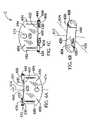
- FIG. 1A is a perspective view of a first sign hanger in accordance with a first preferred embodiment of the present invention
- FIG. 1B is a top plan view of the sign hanger of FIG. 1A ;
- FIG. 1C is a bottom plan view of the sign hanger of FIG. 1A ;
- FIG. 2A is a greatly enlarged perspective view of a portion of the sign hanger of FIG. 1A , showing the details of a centrally located clip;
- FIG. 2B is a greatly enlarged perspective view of another portion of the sign hanger of FIG. 1A , showing the details of a distally located clip;
- FIG. 3 is a schematic illustration showing the sign hanger of FIG. 1 as it is being installed, with an installation tool secured to the end of a telescopic pole, a banner that is shown as being supported by the sign hanger via hooks;
- FIG. 4A is a first view in a sequence, showing a top view of the first sign hanger as it is being rotated into an installed position;
- FIG. 4B is a second and final view in the sequence, showing a top view of the first sign hanger as it is being rotated into an installed position;
- FIG. 5A is a perspective view of a second sign hanger in accord with a second preferred embodiment of the present invention.
- FIG. 5B is a top plan view of the sign hanger of FIG. 5A ;
- FIG. 5C is an enlarged front elevation view of the sign hanger of FIG. 5A ;
- FIG. 6A is a rear elevation view of a third sign hanger in accord with a third preferred embodiment of the present invention.
- FIG. 6B is a top plan view of the sign hanger of FIG. 6A ;
- FIG. 6C is a front elevation view of the sign hanger of FIG. 6A , with the sign hanger upside down;
- FIG. 7 is a greatly enlarged perspective view of rubber strips or pads installed on flange engaging surfaces of a clip
- FIG. 8A is a perspective view of a fourth sign hanger in accordance with a fourth preferred embodiment of the present invention.
- FIG. 8B is a top plan view of the sign hanger of FIG.8A ;
- FIG. 8C is a front elevation of the sign hanger of FIG.8A ;
- FIG. 8D is a partial side elevation of the sign hanger of FIG. 8A ;
- FIG. 8E is a partial side elevation of the sign hanger of FIG. 8A showing an alternate embodiment of a clip portion of the sign hanger.
- FIGS. 1A–1C , 5 A– 5 C, 6 A– 6 C and 8 A– 8 D show first, second, third and fourth sign hangers A, B, C and D respectively, each hanger in accord, respectively, with a first, second, third and fourth preferred embodiments of the present invention.
- the hangers are disclosed as being adapted for use to secure a banner, sign, plant or the like, to an overhead member such as a ceiling grid structure, it should be appreciated that the hanger construction can be utilized for a variety of other purposes as well, such as securing and object, fastened to the hanger, to another member.
- the member to which the hanger is fastened does not need to be an overhead member, such as a ceiling grid. Rather the hangers can be secured to objects located at the base, or walls of a structure, or attached to a section of a vehicle or the like.
- a first sign hanger or support A has an elongated body 10 .
- the elongated body 10 has a first portion having first face or top side 11 and a second face or bottom side 12 .
- First and second clips 14 , 18 extend upward from the top side 11 .
- the first and second clips 14 , 18 are opposedly disposed and laterally separated from a centrally located pivot point 20 and a central transverse axis 22 that runs perpendicularly through an axis of rotation or pivot axis 26 of the body.
- the first sign hanger is rotated about the axis of rotation or pivot axis 26 during the installation process.
- the first clip 14 includes a first base or surface 28 , from which a first arm extends.
- the first arm includes a stem 32 extending upward from the first surface 28 , and a flange 34 supported in a cantilevered manner from the stem 32 .
- the flange 34 includes a first region 36 and a second region 38 .
- a non-binding friction-increasing protrusion, tapered surface or rib 42 projects toward the base surface 28 from the second region 38 .
- the second clip 18 is a mirror image of the first clip 14 . It includes a first or base surface 46 , a stem 48 , and a flange 50 including a first region 52 , a second region 54 , and a protrusion, tapered surface or rib 56 .
- the first sign hanger further includes a first support portion 60 on which the first and second clips 14 , 18 are located.
- the support portion defines a contact surface 61 , which extends across the width of the support portion from a first side edge of the support portion to a second side edge.
- the support portion is shaped as a stylized —Z—, as best seen in FIG. 1B .
- the first surface 28 of the first clip 14 and the first surface 46 of the second clip 18 lie substantially in the same plane.
- the clips define a support body plane.
- a first object support flange 64 extends downward from the second or bottom side 12 of the elongated body 10 at a location beneath the first support portion 60 .
- the first object support flange 64 defines an object support plane.
- the first object support plane can be perpendicular to the support body plane.
- the mounting location of the first object support flange 64 is not critical. Some embodiments in accord with the present invention may not even include the first object support flange.
- the flange 64 is centrally located as depicted in the embodiment under illustration and described above. This allows a load (not shown) to be carried in a balanced fashion. Centrally locating the flange 64 also allows it to be used as a means for rotating the body 10 during an installation process. The installation process will be discussed in greater detail in relation to FIGS. 3 , 4 A and 4 B.
- a support flange is punched and bent from the support body. This creates a void or hole in a contact surface of the prior art object hangers. Additionally, the act of punching and bending the support flange from the support body can bend and deform the contact surface. Creating the void in the support body reduces a contact surface area, thereby reducing a retention friction associated with the contact surface. The deformation can create bumps and dimples in the contact surface that cause the object hanger to be unstable during the installation process, thereby making installation difficult and inconvenient. For the forgoing reasons it is preferable that the contact surface 61 , extend across the width of the support portion from a first side edge of the support portion to a second side edge. Such a contact surface does not contain voids and therefore maximizes a contact surface area and an associated retention friction. Additionally, such a contact surface is smooth and stable, thereby providing for easy and convenient installations.
- the first object support flange 64 includes a means to attach an object to the first sign hanger A.
- the means to attach an object is an eyelet or opening 68 , useful for attaching a hook (not shown) or cord (not shown) or the like.
- Other attachment means are also contemplated.
- an anchor or a hook can be included on the first object support flange.
- the eyelet or opening 68 shown is of a particular size, but other size attachment means are within the scope of the invention. For example, it is possible to include larger openings and, where necessary, a larger first object support flange. Care must be taken however, when contemplating reducing the size of the first object support flange 64 .
- the first object support flange 64 adds strength and rigidity to the central portion of the first sign hanger A.
- the required size and configuration of the first object support flange is a function of the weight the first sign hanger A is intended to carry. Additionally, it is preferable that the size and shape of the first object support flange allow it to fit securely within an installation tool.
- the perimeter rib 70 is preferably sized to provide a snug fit within the installation tool, thereby preventing undue wobbling during an installation or deinstallation process.
- the perimeter rib 70 is a widening rib in that the perimeter rib 70 provides the first object support flange 64 with extra width for strength and for proper tool mating, while allowing the first object support flange 64 to be manufactured with a minimum of material.
- the first sign hanger A is about one foot long and typical dimensions for the first object support flange 64 are, for example, about 1.875 inches ⁇ 0.875 inches.
- a typical perimeter rib width is, for example, about 0.375 inches.
- a second support portion 72 is connected to and extends away from the first support portion 60 in a first direction.
- the second support portion 72 extends along a longitudinal axis 76 of the first sign hanger A and extends a predetermined distance from the pivot point 20 .
- the second support portion 72 terminates in a distal end 78 .
- the longitudinal axis 76 runs parallel to a longitudinal axis of a ceiling grid horizontal flange 80 (see FIG. 4B ) when the first sign hanger 10 is in an installed position.
- the longitudinal axis 76 is centered between the clips 14 , 18 as best seen in FIG. 1B .
- the first object support flange 64 can lie along the longitudinal axis 76 .
- a third support portion 82 is connected to the first support portion 60 .
- the third support portion also extends along the longitudinal axis 76 of the first sign hanger A, the predetermined distance in a direction opposite that of the second support portion 72 .
- the third support portion terminates in a distal end 84 .
- the first sign hanger A has been described as including the first, second, and third support portions ( 60 , 72 , and 82 ).
- the three support portions ( 60 , 72 , and 82 ) are embodied as sections of the single elongated body 10 .
- conventional thermoplastic is softer that typical ceiling grid members. Therefore, sign hangers that include conventional thermoplastic will not gouge or mar the finish of ceiling grid members, even after repeated installations and removals.
- conventional thermoplastics are among the preferred materials for manufacturing the presently described sign hangers.
- a third clip or arm 90 is supported at the distal end 78 of the second support portion and therefore at a first end 92 of the elongated body 10 .
- a fourth clip 94 is supported at the distal end 96 of the third support portion 82 and therefore at a second end 98 of the elongated body 10 .
- the first, second, third and fourth clips 14 , 18 , 90 , and 94 all comprise arms that extend away from the first or top side 11 of the elongated body 10 .
- the third clip 90 includes a first or base surface 100 , from which a third arm extends.
- the third arm includes a stem 104 extending upward from the first surface 100 , and a flange 108 supported in a cantilevered manner from the stem 104 .
- the fourth clip 94 is a mirror image of the third clip and also includes a first or base surface 112 , a stem 114 extending upward from the first surface 112 , and a flange 116 supported in a cantilevered manner from the stem 114 .
- the first surfaces 28 , 46 , 100 , and 112 of each of the first, second, third and fourth clips 14 , 18 , 90 , and 94 comprise four substantially flat co-planar regions supported by the elongated body 10 and lie in, or define, the support body plane.
- the first surfaces 100 , 112 of the third and fourth clips 90 and 94 are located at opposite corners of the first sign hanger A and include downwardly sloping beveled portions 117 , 118 that serve to guide the third and fourth clips 90 and 94 into alignment with the ceiling grid horizontal flange 80 (see FIG. 4A ).
- Shorter beveled surfaces 119 , 120 , 121 , 122 on the clip flanges 34 , 50 , 108 , 116 of all of the clips 14 , 18 , 90 , 94 also aid alignment to ease docking during installation.
- the first sign hanger A is made of a conventional thermoplastic. That thermoplastic is somewhat flexible.
- the second and third support portions 72 and 82 include stiffening ribs 124 .
- the stiffening ribs 124 start adjacent to the first surfaces 28 , 46 of the centrally located clips 14 , 18 , slope immediately below the first surface plane and extend along both sides of the elongated body 10 .
- the stiffening ribs 124 then slope back upward just prior to terminating adjacent to the first surfaces 100 , 112 of the distally located clips 90 , 94 .
- stiffening ribs 124 run below the first surface plane of the clips 14 , 18 , 90 , 94 in order to minimize friction as the first sign hanger A is rotated into an installed position of engagement with the ceiling grid horizontal flange 80 during the installation process (see FIGS. 4A and 4B ).
- a second object support flange 125 extends downward from the bottom or second side 12 of the elongated body 10 , from a position adjacent to the distal end 78 of the second support portion 72 .
- the second support member includes a means for attaching an object to the first sign hanger A.
- the means shown in this embodiment is an eyelet or opening 126 for securement of a cord (not shown) or a hook (not shown), but other attachment means can be used.
- the second object support flange 125 can include an anchor or hook.
- a third object support flange 130 depends downward from the bottom or second side 12 of the elongated body 10 , from a position adjacent to the distal end 96 of the third support portion 82 .
- the third support member 130 includes a means for attaching an object to the first sign hanger A.
- the means for attaching an object shown in this embodiment is an eyelet or opening 134 .
- the second and third support members can lie substantially in the object support plane.
- the first surface 28 , 46 of each clip 14 , 18 is substantially flat.
- the first support portion 60 of the elongated body 10 holds the first surfaces 28 , 46 of each clip 14 , 18 in a co-planar fashion (in the support body plane).
- Extending upward from each first surface 28 , 46 is a stem 32 , 48 .
- Each stem 32 , 48 extends a distance approximating the thickness of the horizontal flange 80 of a conventional inverted T-shaped ceiling grid member 140 (see FIG. 4A ) that the clip is meant to engage.
- the stems 32 , 48 are laterally displaced from each other. The distance they are laterally displaced depends on the width of the ceiling grid horizontal flange they will engage.
- a typical lateral displacement distance for the stems is, for example, about one inch.
- An example of a typical stem height is about 0.063 inches.
- first regions 36 , 52 are substantially flat.
- the first regions 36 , 52 act as stabilizers and rest points during the installation process. The function of the first regions 36 , 52 will be discussed in greater detail below, in reference to FIG. 4B .
- the second regions 38 , 54 of each centrally located clip 14 , 18 each include the protrusions, tapered surfaces or ribs 42 , 56 .
- the ribs 42 , 56 are preferably molded in place. As the ribs 42 , 56 engage the flange 80 (see FIG. 4A ) of the grid element 140 , a lifting torque is applied to the flanges 34 , 50 and they are bent slightly upward.
- the flanges 34 , 50 are made of a stiff but resilient material, and so, act as springs under compression. The slight bending upward of the flanges 34 , 50 increases the gripping force applied to a surface (as opposed to an edge) of the horizontal flange 80 of the grid element 140 .
- the flanges 34 , 50 of the centrally located clips 14 , 18 of the preferred first sign hanger embodiment each have a notch 150 , 154 , or absence of material, near the ribs 42 , 58 . It is preferable to mold features, such as ribs 42 , 58 , near the edge of structures such as the central clip flanges 34 , 50 . If the notches are not provided, then the edge of the second portions 38 , 54 of the central clips 14 , 18 , and, therefore, the ribs 42 , 58 , would be positioned such that the ribs would engage the horizontal flange undesirably early in the installation process. Therefore, it is preferable that the notches 150 , 154 are provided.
- one embodiment of the first sign hanger can be molded from a conventional thermoplastic, such as Acrylonitrile-Butadiene-Styrene (commonly known in the art as ABS).
- ABS Acrylonitrile-Butadiene-Styrene
- other conventional materials such as, for example, nylon or spring steel, can be used to make the sign hanger and still remain within the scope of the invention.
- a friction-increasing device such as, for example, a protrusion, tapered surface or rib can be located on other surfaces. For example, as will be discussed in greater detail in reference to FIG. 7 and FIGS.
- a protrusion, tapered surface or rib can be located on the first surface 28 of the clip 14 , or on some other surface of the sign hanger that engages a portion of the horizontal grid work member.
- the sign hanger, or at least the ceiling grid engaging portions of the sign hanger, such as, for example, the ribs, protrusions or tapered surfaces comprise a material that will not gouge the ceiling grid (e.g. ABS or Nylon).
- While the preferred embodiment is a one-piece molding, an assembly having, for example, discrete clips, can be made and still remain within the scope of the invention.
- other non-binding, friction-increasing devices can be used in place of or in addition to the protrusions, tapered surfaces or ribs.
- rubber strips or pads 156 can be applied to any surface that engages a surface (as opposed to, for example, an edge) of the ceiling grid horizontal flange 80 of the grid work member 140 .
- the rubber strips or pads 156 can be beveled or tapered. Such an embodiment would remain within the scope of the invention.
- the pads 156 are protrusions, tapered surfaces or ribs of one piece with the sign hanger.
- the protrusions are molded into the sign hanger in the same manner as the rest of the parts or portions of the sign hanger.
- the pads, tapered surfaces or protrusions 156 can extend upward from a base surface and/or depend downward from a clip flange or arm. When located on a base surface, the pads, tapered surfaces or protrusions can be located under a clip flange or somewhere else on the base surface. For example, as will be discussed in greater detail in reference to FIGS. 8A–8E , a pad, tapered surface, or plateau can be located on a base surface between two or more clips.
- the best location for a given hanger design is a function of the clip design and operational parameters, such as, for example, intended supported object weight, intended ceiling grid dimensions, and desired gripping force.
- pads are preferable because they can be replaced when they become worn.
- protrusions, ribs, or plateaus that are of one piece with the sign hanger are preferred.
- One-piece construction is desirable because it is simple, and inexpensive, requiring no labor for assembly. Additionally, in one-piece construction there are no loose pieces that can fall off due to adhesive age or loosened fasteners.
- the distally located clips 90 , 94 do not include friction-increasing devices such as ribs, protrusions or tapered surfaces.
- friction-increasing devices could be included on the distally located clips 90 , 94 if additional friction were required or found to be beneficial.
- FIG. 3 illustrates the installation process.
- An installer attaches an object, for example a sign or banner 200 , to the first sign hanger A with some attachment means such as, for example, hooks 204 or cord (not shown). Since the sign or banner 200 illustrated is relatively wide, the sign or banner is hooked through eyelets in the second and third object support flanges 125 , 130 .
- a conventional installation tool 210 is shown at the end of a telescopic pole 214 .
- the first object support flange 64 can be received in a socket 216 in the installation tool 210 and the first sign hanger A, together with the banner 200 , can be lifted upward until the first sign hanger engages the horizontal flange 80 of the grid element 140 . Then the installer can rotate the first sign hanger 10 into an installed position (see FIGS. 4A and 4B ).
- the widening or perimeter rib 70 provides a snug fit for the first object support flange 64 within the socket 216 of the installation tool.
- FIG. 4A the first sign hanger A is placed against the horizontal flange 80 in an unengaged position. In this position the sign hanger A is oriented normal to the longitudinal axis of the horizontal flange 80 of grid work element 140 . It is clear that the clips 14 , 18 just clear the width of the flange 80 .
- FIG. 4B shows the first sign hanger A at an intermediate position as it is being rotated into engagement with the horizontal flange 80 . The first regions 36 , 52 of the flanges 34 , 50 of the centrally located clips 14 , 18 are partially engaging the upper surface of the horizontal flange 80 .
- a second sign hanger or support B has first and second clips 304 , 308 opposedly disposed and laterally separated from a transverse axis 312 that runs perpendicularly through an axis of rotation or pivot axis 316 at a pivot point 322 .
- the second sign hanger B is rotated about the axis of rotation or pivot axis 316 during the installation process.
- the first clip 304 includes a first or base surface 326 , and an arm comprising a stem 332 extending upward from the first surface 326 , and a flange 336 supported in a cantilevered manner from the stem 332 .
- a non-binding, friction-increasing device such as, a protrusion, tapered surface or rib 340 , is included on the flange 336 .
- the second clip 308 also includes a first surface 344 , a stem 348 , and a flange 352 including a non-binding, friction-increasing protrusion, tapered surface or rib 356 .
- the flanges 336 , 352 of the first and second clips 04 , 308 extend toward a longitudinal axis 358 of the sign hanger B from their respective stems 332 , 348 .
- the longitudinal axis 358 is a line that runs parallel to the ceiling grid work when the second sign hanger B is in an installed position.
- the longitudinal axis 358 is centered between the clips 304 , 308 .
- the ribs 340 , 356 are friction-increasing and operate in a manner similar to that described in reference to the first sign hanger A.
- protrusions or tapered surfaces may be included instead of, or in addition to, the ribs 340 , 356 .
- the second sign hanger B further includes a circular first support portion 360 having a first or top side 361 and a second or bottom side 362 .
- the first support portion 360 interconnects the first surface 326 of the first clip 304 and the first surface 344 of the second clip 308 .
- the support portion 360 can lie in a support body plane.
- An object support flange 364 depends downward from the first support portion 360 .
- the object support flange defines an object support plane.
- the object support plane can be substantially perpendicular to the support body plane.
- the flange 364 includes a means to attach an object to the second sign hanger B.
- the illustrated embodiment includes an eyelet or opening 368 , useful for attaching a hook (not shown) or cord (not shown) or the like, but other attachment means are contemplated.
- an anchor or a hook can be included on the flange 364 .
- the eyelet or opening 368 shown is of a particular size, but other sizes are within the scope of the invention.
- anchors or hooks can be included on the flange.
- the second sign hanger B can be installed by hand or in a manner similar to that described with reference to the first sign hanger A. Where the installation tool is used, the object to be supported is generally attached to the first object support flange after the second sign hanger is installed on a ceiling.
- the illustrated object support flange 364 of the second sign hanger B is of sufficient thickness to fit snugly within the socket of the installation tool. Therefore, the object support flange 364 does not include widening ribs.
- a third sign hanger or support C has a first and second clip 404 , 408 opposedly disposed and laterally separated from a transverse axis 412 that runs perpendicularly through an axis of rotation 416 at a pivot point 420 .
- the third sign hanger C is rotated about the axis of rotation 416 during the installation process in a manner similar to that described in reference to the first sign hanger A.
- the first clip 404 includes a first or base surface 424 , and an arm comprising a stem 428 extending upward from the first surface 424 , and a flange 432 supported in a cantilevered manner from the stem 428 .
- a non-binding, friction-increasing device such as a protrusion, tapered surface or rib 436 is included on the flange 432 .
- the second clip 408 includes a first or base surface 440 , a stem 444 , and a flange 446 including a non-binding, friction-increasing protrusion, tapered surface or rib 450 .
- the flanges 432 , 446 of the first and second clips 404 , 408 extend toward a longitudinal axis 454 from their respective stems 428 , 444 .
- the longitudinal axis 454 is a line that runs parallel to the ceiling grid when the third sign hanger C is in an installed position.
- the longitudinal axis 454 is centered between the clips 404 , 408 .
- the ribs 436 , 450 are friction-increasing and operate in a manner similar to that described in reference to the first sign hanger A.
- the third sign hanger C further includes a trapezoidal or rectangular first support portion 460 including a top side 461 and a bottom side 462 .
- the first support portion interconnects the first surface 424 of the first clip 404 and the first surface 440 of the second clip 408 .
- the first support portion defines in a support body plane.
- An object support flange 470 depends downward from the first support portion 460 .
- the first object support flange 470 includes a means to attach an object to the third sign hanger C.
- the means to attach an object to the third sign hanger C is an anchor 474 suitable for looping an end of a string (not shown) or cord (not shown) around, but other attachment means are contemplated.
- an eyelet, opening or hook can be included on the first object support flange.
- the first object support flange 470 also includes first and second projections 480 , 484 for preventing a stored string (not shown), looped around the first object support flange, from slipping and sliding off the first object support flange 470 . Additionally, the first object support flange 470 includes first and second slots 490 , 494 . The slots 490 , 494 can be used to secure the end of the string (not shown) when it is in the stored configuration, thereby preventing the looped string from unraveling.
- the third sign hanger C can be installed by hand or in a manner similar to that described with reference to the first sign hanger A. Where the installation tool 210 is used, the object to be supported, is generally attached to the first object support flange 470 after the third sign hanger C is installed on the ceiling grid.
- a fourth sign hanger or support D has a first and second clip 804 , 808 opposedly disposed and laterally separated from a transverse axis 812 that runs perpendicularly through an axis of rotation or pivot axis 816 at a pivot point 820 .
- the fourth sign hanger D is rotated about the axis of rotation 816 during the installation process in a manner similar to that described in reference to the first sign hanger A.
- the first clip 804 includes a first or base surface 824 , and an arm comprising a stem 828 extending upward from the first surface 824 , and a flange 832 supported in a cantilevered manner from the stem 828 .
- a non-binding, friction-increasing device such as a protrusion, rib or tapered surface 836 is included on a wall of the flange 832 .
- the second clip 808 includes a first or base surface 840 , a stem 844 , and a flange 846 including a non-binding, friction-increasing protrusion, rib or tapered surface 850 on a wall of the flange 846 .
- the flanges 832 , 846 of the first and second clips 804 , 808 extend toward a longitudinal axis 854 from their respective stems 828 , 844 .
- the longitudinal axis 854 is a line that runs parallel to the ceiling grid when the fourth sign hanger D is in an installed position.
- the longitudinal axis 854 is centered between the clips 804 , 408 .
- the tapered areas 836 , 850 are on the flanges 832 and 846 and the tapering extends towards the longitudinal axis 854 .
- the tapered areas 836 , 850 of the flange walls each extend across a width of their respective arms. Extending the tapered surfaces over the width of the arm maximizes a sliding surface area as well as a retention contact surface area that the tapered surfaces can produce against an associated ceiling grid member.
- the flange tapered surfaces 836 , 850 are friction-increasing and operate in a manner similar to that of the ribs or protrusions described in reference to the first sign hanger A. However, instead of engaging a ceiling grid element suddenly, during an installation process, the tapered surfaces enable the flanges to gradually engage the ceiling grid member, increasing a resistance to movement as the ceiling grid member is brought into deeper engagement with clips 804 , 808 .
- the flanges 832 , 846 include relatively thin neck regions 856 , 858 .
- the neck regions are thin enough to allow the flanges 832 , 846 to flex slightly as the ceiling grid element comes into engagement with the clips 804 , 808 .
- An exemplary neck thickness, for a fourth sign hanger D made of ABS is about 0.080 inches.
- the neck region has a rectangular lower surface.
- the neck regions can include reverse tapered surfaces 859 having thinnest regions closer to the stems 828 , 844 .
- Such reverse tapered surfaces 859 concentrate all flexing stresses at region 860 where the flanges 832 , 846 meet the stems 828 , 844 , thereby increasing a spring force associated with flexing the flanges 832 , 846 .
- an associated ceiling grind member has a bulbous or curled edge portion
- the neck portions 856 , 858 or stress regions 860 are operative to capture or partially surround the bulbous or curled portion when the object hanger is in a installed position. This capturing of the bulbous or curled portion provides an additional retention force for the object hanger.
- the support portion or body 861 includes a friction increasing protrusion or plateau 864 .
- the friction increasing protrusion or plateau 864 acts as a pivot area and contact surface around which clipping forces of the clips 804 , 808 , in engagement with a ceiling grid element, tend to bend or flex at least one of the sign hanger and the ceiling grid element. In this manner, one or both of the ceiling grid element and the sign hanger, are placed in a friction or grip increasing tension. In effect, the plateau 864 reduces a clip gap 899 associated with the first and second clips 804 , 808 .
- the reduction in the clip gap 899 leads to a tighter fit between the clips of the fourth sign hanger D and an associated ceiling member (not shown).
- the tighter fit leads to an increase in flange 832 , 846 flexure when the clips 804 , 808 engage the associated ceiling member.
- the increase in flexure leads to an increase in clip spring force, which results in an increased gripping force applied, between the sign hanger and the ceiling member.
- the first and second protrusions, ribs or tapered surfaces 836 , 850 and the friction increasing protrusion or plateau 864 releasably grip opposed surfaces of the associated ceiling grid.
- the clip gap 899 may be reduced by shortening the stems 828 , 844 or by altering the dimensions of the protrusions or tapered surfaces.
- these solutions can be difficult to achieve with inexpensive molding techniques or without the use of secondary finishing operations.
- the plateau 864 achieves the desired gap reduction while permitting the use of inexpensive molding techniques.
- the plateau 864 extends approximately transversely to the longitudinal axis 854 across the support body 861 top side 862 from one side edge to another side edge. Extending the plateau 864 across the support body improves a stability of the sign hanger during the installation process. For example, if a centrally located plateau is used that extends only partially across the support body 861 , then any misalignment that occurs before the clips are rotated into engagement with an associated ceiling member might lead to wobbling. The wobbling would make it more difficult to install the sign hanger.
- the plateau 861 can be fairly wide, perhaps, on the order of being half as wide as the horizontal ceiling grid member. In one exemplary embodiment of the illustrated sign hanger D, the plateau 861 is 0.5 inches wide, 1.2 inches long and is raised 0.02 inches above the surface of the support body 860 . Preferably the plateau, in its role as a contact surface, does not include voids or destabilizing surface distortions.
- An object support flange 870 depends downward from the support portion or body 861 .
- the object support flange 870 includes a means to attach an object to the fourth sign hanger D.
- the means to attach an object to the fourth sign hanger D is an anchor 874 suitable for looping an end of a string (not shown) or cord (not shown) around.
- an eyelet, opening 875 is also included on the object support flange 870 .
- a hook or other mounting device can be included on the object support flange 870 .
- the anchor 874 includes first and second slots 876 , 878 .
- the slots 890 , 894 can be used to secure an end of the string (not shown) to the anchor.
- the end of the string can be secured in the first slot 876 , wrapped halfway around the anchor and secured in the second slot, and wrapped another half turn around the anchor and secured again in the first slot. This process can be repeated until the friction between the slots 876 , 878 and the string is sufficient to keep the string from unraveling. In this way a string can be attached to the sign hanger D without the use of knots. Knots tend to weaken a string and are difficult to untie when the string must be replaced.
- the object support flange 870 also includes first and second projections 880 , 884 for preventing a stored string (not shown), looped around the first object support flange, from slipping and sliding off the object support flange 870 . Additionally, the object support flange 870 includes third and fourth slots 890 , 894 . The slots 890 , 894 can be used to secure the end of the string (not shown) when it is in the stored configuration, thereby preventing the looped string from unraveling.
- the fourth sign hanger D can be installed and deinstalled by hand or in a manner similar to that described with reference to the first sign hanger A. No prying tools such as a screwdriver to pair of pliers are required to remove the fourth sign hanger. Therefore, the fourth sign hanger is releasable in the sense defined above. Where the installation tool 210 is used, the object to be supported is generally attached to the object support flange 870 after the third sign hanger C is installed on the ceiling grid.
- the sign, banner or object hangers described above have a reduced risk of accidental disengagement. At least one of them enables a one step attachment of a banner to a ceiling grid, rather than requiring the installation of several spaced clips for supporting the banner. They allow for the secure, temporary attachment, of signs, plants, banners and the like, to suspended or dropped ceiling support grids, without requiring the use of a ladder. They do not bind with the ceiling grid. Therefore they do not scratch and mar the ceiling grid surface. Furthermore, they can be removed without the use of screwdrivers, pliers or similar prying devices. While the object hangers can be easily removed when desired, with minimal effort, they include pads, ribs, tapered surfaces and/or plateaus that resist accidental rotation and disengagement.
- pads, ribs, tapered surfaces and plateaus can embody friction-increasing means for enhancing a releasable holding power of the object hanger on a ceiling grid.
- Their structure resists rotation, to a limited extent, so they are relatively easy to suspend, then lock in place on a ceiling grid, while at the same time being removable and reusable.
Abstract
Description
Claims (18)
Priority Applications (1)
| Application Number | Priority Date | Filing Date | Title |
|---|---|---|---|
| US10/083,251 US6976662B2 (en) | 2000-03-01 | 2001-10-22 | Ceiling grid sign hanger |
Applications Claiming Priority (2)
| Application Number | Priority Date | Filing Date | Title |
|---|---|---|---|
| US51655100A | 2000-03-01 | 2000-03-01 | |
| US10/083,251 US6976662B2 (en) | 2000-03-01 | 2001-10-22 | Ceiling grid sign hanger |
Related Parent Applications (1)
| Application Number | Title | Priority Date | Filing Date |
|---|---|---|---|
| US51655100A Continuation-In-Part | 2000-03-01 | 2000-03-01 |
Publications (2)
| Publication Number | Publication Date |
|---|---|
| US20020148938A1 US20020148938A1 (en) | 2002-10-17 |
| US6976662B2 true US6976662B2 (en) | 2005-12-20 |
Family
ID=24056078
Family Applications (1)
| Application Number | Title | Priority Date | Filing Date |
|---|---|---|---|
| US10/083,251 Expired - Lifetime US6976662B2 (en) | 2000-03-01 | 2001-10-22 | Ceiling grid sign hanger |
Country Status (1)
| Country | Link |
|---|---|
| US (1) | US6976662B2 (en) |
Cited By (8)
| Publication number | Priority date | Publication date | Assignee | Title |
|---|---|---|---|---|
| US20060022107A1 (en) * | 2004-07-30 | 2006-02-02 | Leng Lim | Ceiling mount |
| US20060180281A1 (en) * | 2005-01-13 | 2006-08-17 | Michael Hoermann | Apparatus to suspend garage door drives |
| US20100025553A1 (en) * | 2007-02-07 | 2010-02-04 | White Keith D | Mounting system for comestible fluid dispensing components and accessories |
| US20100148028A1 (en) * | 2008-12-15 | 2010-06-17 | Hand James A | Adjustable, retractable ceiling and wall hanging system |
| US20160265718A1 (en) * | 2015-03-04 | 2016-09-15 | K-International, Inc. | Sign suspender for mounting in channel for ladderless display |
| US20190257500A1 (en) * | 2018-02-22 | 2019-08-22 | Eaton Intelligent Power Limited | Adjustable Sensor Mounting System |
| US10533703B1 (en) * | 2018-09-07 | 2020-01-14 | Hewlett Packard Enterprise Development Lp | Mounting system for tool-less attachment of electronic device to a rail |
| US11326735B1 (en) * | 2018-07-21 | 2022-05-10 | Juniper Networks, Inc. | Toolless mounting of electronic devices |
Families Citing this family (2)
| Publication number | Priority date | Publication date | Assignee | Title |
|---|---|---|---|---|
| US20080204369A1 (en) * | 2005-05-24 | 2008-08-28 | Messagenet Systems, Inc. | System for Displaying Electronic Visual Messages Adjacent a Suspended Ceiling |
| US7805904B2 (en) * | 2008-01-17 | 2010-10-05 | Target Brands, Inc. | Ceiling grid spanner |
Citations (28)
| Publication number | Priority date | Publication date | Assignee | Title |
|---|---|---|---|---|
| US1662539A (en) * | 1927-08-15 | 1928-03-13 | Cincinnati Butchers Supply Co | Supporting means for overhead tracks |
| US2590030A (en) * | 1951-03-02 | 1952-03-18 | Charles F Obert | Ironing board rail |
| US2942314A (en) * | 1955-05-31 | 1960-06-28 | Gen Electric | Double-ended cord holder |
| US3003735A (en) | 1960-06-21 | 1961-10-10 | Erico Prod Inc | Suspension clip |
| US3018080A (en) | 1959-03-18 | 1962-01-23 | Minerallac Electric Company | Scissor-clip |
| US3100319A (en) | 1960-05-16 | 1963-08-13 | Wood Conversion Co | Ceiling structure and tile therefor |
| US3371900A (en) * | 1966-02-14 | 1968-03-05 | Prudential Lighting Corp | Unitary double-detent connector for lighting fixtures |
| US3575371A (en) * | 1969-02-06 | 1971-04-20 | Paul A Carlstedt | Rope-mounting bracket |
| US3589660A (en) | 1970-03-05 | 1971-06-29 | Nat Service Ind Inc | Lighting fixture hanger |
| US3743228A (en) | 1971-05-10 | 1973-07-03 | E Drab | Hanger clip for suspended ceilings |
| US3952985A (en) | 1974-11-25 | 1976-04-27 | Fastway Fasteners, Inc. | Clip for hanging signs |
| US4025019A (en) | 1976-10-07 | 1977-05-24 | Skyhook Sales Corporation | Ceiling fixture and hanging clamp assembly |
| US4065090A (en) | 1976-03-05 | 1977-12-27 | Mauney Harold D | Clip assembly for ceiling track railings |
| US4073458A (en) | 1976-10-05 | 1978-02-14 | Sease True F | Hanger clip for displaying articles from suspended ceilings |
| US4112550A (en) | 1977-05-13 | 1978-09-12 | Dewitt Stuart | Suspended ceiling hook |
| US4118000A (en) | 1977-04-07 | 1978-10-03 | George C. Ballas | Apparatus for supporting a member from a drop-tile ceiling |
| US4135692A (en) | 1978-01-05 | 1979-01-23 | Ferguson William J | Hanger device |
| US4163576A (en) | 1978-04-24 | 1979-08-07 | Hoop James B | Means for suspending articles from a ceiling |
| US4191352A (en) | 1978-08-21 | 1980-03-04 | Fastway Fasteners, Inc. | Rotatably installed suspension clip |
| US4291855A (en) * | 1976-03-15 | 1981-09-29 | Egli, Fischer & Co. Ag | Pipe clamp |
| US4315611A (en) | 1978-07-05 | 1982-02-16 | Hoop James B | Device for suspending articles from a ceiling or the like |
| US4323215A (en) | 1980-03-10 | 1982-04-06 | Berger Sol J | Hang-up fixture |
| US4422609A (en) | 1981-08-14 | 1983-12-27 | The United States Of America As Represented By The Administrator Of The National Aeronautics And Space Administration | Clamp-mount device |
| US4564165A (en) | 1983-03-31 | 1986-01-14 | Hallmark Cards, Inc. | Attaching device |
| US4667913A (en) | 1986-04-30 | 1987-05-26 | Clevepak Corporation | Device for suspending objects |
| US5024405A (en) * | 1989-05-12 | 1991-06-18 | Mcguire Robert H | Pipe clamp |
| US5230488A (en) * | 1992-07-14 | 1993-07-27 | Condon Duane R | Clip-on pipe hanging clamp |
| US5490651A (en) | 1993-08-20 | 1996-02-13 | Fasteners For Retail, Inc. | Hinged ceiling clip |
-
2001
- 2001-10-22 US US10/083,251 patent/US6976662B2/en not_active Expired - Lifetime
Patent Citations (28)
| Publication number | Priority date | Publication date | Assignee | Title |
|---|---|---|---|---|
| US1662539A (en) * | 1927-08-15 | 1928-03-13 | Cincinnati Butchers Supply Co | Supporting means for overhead tracks |
| US2590030A (en) * | 1951-03-02 | 1952-03-18 | Charles F Obert | Ironing board rail |
| US2942314A (en) * | 1955-05-31 | 1960-06-28 | Gen Electric | Double-ended cord holder |
| US3018080A (en) | 1959-03-18 | 1962-01-23 | Minerallac Electric Company | Scissor-clip |
| US3100319A (en) | 1960-05-16 | 1963-08-13 | Wood Conversion Co | Ceiling structure and tile therefor |
| US3003735A (en) | 1960-06-21 | 1961-10-10 | Erico Prod Inc | Suspension clip |
| US3371900A (en) * | 1966-02-14 | 1968-03-05 | Prudential Lighting Corp | Unitary double-detent connector for lighting fixtures |
| US3575371A (en) * | 1969-02-06 | 1971-04-20 | Paul A Carlstedt | Rope-mounting bracket |
| US3589660A (en) | 1970-03-05 | 1971-06-29 | Nat Service Ind Inc | Lighting fixture hanger |
| US3743228A (en) | 1971-05-10 | 1973-07-03 | E Drab | Hanger clip for suspended ceilings |
| US3952985A (en) | 1974-11-25 | 1976-04-27 | Fastway Fasteners, Inc. | Clip for hanging signs |
| US4065090A (en) | 1976-03-05 | 1977-12-27 | Mauney Harold D | Clip assembly for ceiling track railings |
| US4291855A (en) * | 1976-03-15 | 1981-09-29 | Egli, Fischer & Co. Ag | Pipe clamp |
| US4073458A (en) | 1976-10-05 | 1978-02-14 | Sease True F | Hanger clip for displaying articles from suspended ceilings |
| US4025019A (en) | 1976-10-07 | 1977-05-24 | Skyhook Sales Corporation | Ceiling fixture and hanging clamp assembly |
| US4118000A (en) | 1977-04-07 | 1978-10-03 | George C. Ballas | Apparatus for supporting a member from a drop-tile ceiling |
| US4112550A (en) | 1977-05-13 | 1978-09-12 | Dewitt Stuart | Suspended ceiling hook |
| US4135692A (en) | 1978-01-05 | 1979-01-23 | Ferguson William J | Hanger device |
| US4163576A (en) | 1978-04-24 | 1979-08-07 | Hoop James B | Means for suspending articles from a ceiling |
| US4315611A (en) | 1978-07-05 | 1982-02-16 | Hoop James B | Device for suspending articles from a ceiling or the like |
| US4191352A (en) | 1978-08-21 | 1980-03-04 | Fastway Fasteners, Inc. | Rotatably installed suspension clip |
| US4323215A (en) | 1980-03-10 | 1982-04-06 | Berger Sol J | Hang-up fixture |
| US4422609A (en) | 1981-08-14 | 1983-12-27 | The United States Of America As Represented By The Administrator Of The National Aeronautics And Space Administration | Clamp-mount device |
| US4564165A (en) | 1983-03-31 | 1986-01-14 | Hallmark Cards, Inc. | Attaching device |
| US4667913A (en) | 1986-04-30 | 1987-05-26 | Clevepak Corporation | Device for suspending objects |
| US5024405A (en) * | 1989-05-12 | 1991-06-18 | Mcguire Robert H | Pipe clamp |
| US5230488A (en) * | 1992-07-14 | 1993-07-27 | Condon Duane R | Clip-on pipe hanging clamp |
| US5490651A (en) | 1993-08-20 | 1996-02-13 | Fasteners For Retail, Inc. | Hinged ceiling clip |
Non-Patent Citations (1)
| Title |
|---|
| FFR 1999 Yellow Pages Catalogue, Cover Page and pp. 76-80. |
Cited By (12)
| Publication number | Priority date | Publication date | Assignee | Title |
|---|---|---|---|---|
| US20060022107A1 (en) * | 2004-07-30 | 2006-02-02 | Leng Lim | Ceiling mount |
| US20060180281A1 (en) * | 2005-01-13 | 2006-08-17 | Michael Hoermann | Apparatus to suspend garage door drives |
| US20100025553A1 (en) * | 2007-02-07 | 2010-02-04 | White Keith D | Mounting system for comestible fluid dispensing components and accessories |
| US20100148028A1 (en) * | 2008-12-15 | 2010-06-17 | Hand James A | Adjustable, retractable ceiling and wall hanging system |
| US8770533B2 (en) | 2008-12-15 | 2014-07-08 | James Arthur Hand | Adjustable, retractable ceiling and wall hanging system |
| US20160265718A1 (en) * | 2015-03-04 | 2016-09-15 | K-International, Inc. | Sign suspender for mounting in channel for ladderless display |
| US9984599B2 (en) * | 2015-03-04 | 2018-05-29 | K-International, Inc. | Sign suspender for mounting in channel for ladderless display |
| US20190257500A1 (en) * | 2018-02-22 | 2019-08-22 | Eaton Intelligent Power Limited | Adjustable Sensor Mounting System |
| US10724714B2 (en) * | 2018-02-22 | 2020-07-28 | Signify Holding B.V. | Adjustable sensor mounting system |
| US11326735B1 (en) * | 2018-07-21 | 2022-05-10 | Juniper Networks, Inc. | Toolless mounting of electronic devices |
| US11725775B1 (en) | 2018-07-21 | 2023-08-15 | Juniper Networks, Inc. | Toolless mounting of electronic devices |
| US10533703B1 (en) * | 2018-09-07 | 2020-01-14 | Hewlett Packard Enterprise Development Lp | Mounting system for tool-less attachment of electronic device to a rail |
Also Published As
| Publication number | Publication date |
|---|---|
| US20020148938A1 (en) | 2002-10-17 |
Similar Documents
| Publication | Publication Date | Title |
|---|---|---|
| US6976662B2 (en) | Ceiling grid sign hanger | |
| US5367750A (en) | Wiring harness clip | |
| US6719260B1 (en) | Apparatuses and methods for hanging frames | |
| AU2003201362B2 (en) | Hanger assembly | |
| US8322297B2 (en) | Securing device | |
| US8959814B2 (en) | Poster clamp, and system and method using same | |
| US5112014A (en) | Peg board hangers and retainers | |
| EP0678635A1 (en) | Hanger | |
| US4315611A (en) | Device for suspending articles from a ceiling or the like | |
| US20090236477A1 (en) | Cable support and method | |
| US20040111995A1 (en) | Hanger system | |
| US10876682B2 (en) | Wall mountable support | |
| US11674637B2 (en) | Anchor assembly | |
| US4221355A (en) | Device for suspending articles from a ceiling or the like | |
| US5482244A (en) | Hanger | |
| US10605403B2 (en) | Cantilevered screwless hanger | |
| JPH0726426U (en) | Base material hanging hanger | |
| JPH0353555Y2 (en) | ||
| US20220337041A1 (en) | Data Cable Support | |
| JP2003097098A (en) | Stopper for sheets | |
| JP3040443U (en) | Hanging hook | |
| KR200407551Y1 (en) | Billboard ceiling hooks for billboards | |
| JP3107999U (en) | Tool holder for safety belt | |
| JPH1018502A (en) | Ceiling material attaching device | |
| JPH10105U (en) | Piping support |
Legal Events
| Date | Code | Title | Description |
|---|---|---|---|
| AS | Assignment |
Owner name: FASTENERS FOR RETAIL, INC., OHIO Free format text: ASSIGNMENT OF ASSIGNORS INTEREST;ASSIGNORS:KUMP, DANIEL J.;WAMSLEY, STEPHEN D.;KOSIR, JOSEPH P.;REEL/FRAME:012505/0654;SIGNING DATES FROM 20011017 TO 20011018 |
|
| AS | Assignment |
Owner name: ANTARES CAPITAL CORPORATION, AS FIRST LIEN COLLATE Free format text: SECURITY AGREEMENT;ASSIGNOR:FASTENERS FOR RETAIL, INC.;REEL/FRAME:015361/0135 Effective date: 20040527 |
|
| AS | Assignment |
Owner name: ANTARES CAPITAL CORPORATION, AS SECOND LIEN COLLAT Free format text: SECURITY INTEREST;ASSIGNOR:FASTENERS FOR RETAIL, INC.;REEL/FRAME:015370/0165 Effective date: 20040527 |
|
| STCF | Information on status: patent grant |
Free format text: PATENTED CASE |
|
| AS | Assignment |
Owner name: GENERAL ELECTRIC CAPITAL CORPORATION, AS AGENT,ILL Free format text: SECURITY AGREEMENT;ASSIGNOR:FASTENERS FOR RETAIL, INC.;REEL/FRAME:018524/0236 Effective date: 20061115 Owner name: FASTENERS FOR RETAIL, INC., OHIO Free format text: RELEASE BY SECURED PARTY;ASSIGNOR:ANTARES CAPITAL CORPORATION, AS FIRST LIEN COLLATERAL AGENT;REEL/FRAME:018524/0172 Effective date: 20061115 Owner name: FASTENERS FOR RETAIL, INC., OHIO Free format text: RELEASE BY SECURED PARTY;ASSIGNOR:ANTARES CAPITAL CORPORATION, AS SECOND LIEN COLLATERAL AGENT;REEL/FRAME:018524/0218 Effective date: 20061115 Owner name: GENERAL ELECTRIC CAPITAL CORPORATION, AS AGENT, IL Free format text: SECURITY AGREEMENT;ASSIGNOR:FASTENERS FOR RETAIL, INC.;REEL/FRAME:018524/0236 Effective date: 20061115 |
|
| FPAY | Fee payment |
Year of fee payment: 4 |
|
| AS | Assignment |
Owner name: GENERAL ELECTRIC CAPITAL CORPORATION, AS AGENT, IL Free format text: SECURITY AGREEMENT;ASSIGNOR:FASTENERS FOR RETAIL, INC.;REEL/FRAME:026572/0960 Effective date: 20110711 |
|
| AS | Assignment |
Owner name: FASTENERS FOR RETAIL, INC., OHIO Free format text: PATENT RELEASE OF PATENT SECURITY AGREEMENT ORIGINALLY RECORDED AT REEL/FRAME 018524/0236;ASSIGNOR:GENERAL ELECTRIC CAPITAL CORPORATION, AS AGENT;REEL/FRAME:026582/0691 Effective date: 20110711 |
|
| FPAY | Fee payment |
Year of fee payment: 8 |
|
| AS | Assignment |
Owner name: ANTARES CAPITAL LP, ILLINOIS Free format text: ASSIGNMENT OF INTELLECTUAL PROPERTY SECURITY AGREEMENT;ASSIGNOR:GENERAL ELECTRIC CAPITAL CORPORATION;REEL/FRAME:036754/0062 Effective date: 20150821 |
|
| FEPP | Fee payment procedure |
Free format text: PAYER NUMBER DE-ASSIGNED (ORIGINAL EVENT CODE: RMPN); ENTITY STATUS OF PATENT OWNER: LARGE ENTITY Free format text: PAYOR NUMBER ASSIGNED (ORIGINAL EVENT CODE: ASPN); ENTITY STATUS OF PATENT OWNER: LARGE ENTITY |
|
| FPAY | Fee payment |
Year of fee payment: 12 |
|
| FEPP | Fee payment procedure |
Free format text: ENTITY STATUS SET TO UNDISCOUNTED (ORIGINAL EVENT CODE: BIG.) |
|
| AS | Assignment |
Owner name: ANTARES CAPITAL LP, AS AGENT, ILLINOIS Free format text: SECURITY INTEREST;ASSIGNOR:FASTENERS FOR RETAIL, INC.;REEL/FRAME:052019/0315 Effective date: 20200225 |
|
| AS | Assignment |
Owner name: FASTENERS FOR RETAIL, INC., OHIO Free format text: RELEASE BY SECURED PARTY;ASSIGNOR:ANTARES CAPITAL LP (AS SUCCESSOR IN INTEREST TO GENERAL ELECTRIC CAPITAL CORPORATION);REEL/FRAME:061370/0295 Effective date: 20220901 Owner name: FASTENERS FOR RETAIL, INC., OHIO Free format text: RELEASE BY SECURED PARTY;ASSIGNOR:ANTARES CAPITAL LP (AS SUCCESSOR IN INTEREST TO GENERAL ELECTRIC CAPITAL CORPORATION);REEL/FRAME:061370/0226 Effective date: 20220901 |