US6975647B2 - Enhancements for TCP performance enhancing proxies - Google Patents
Enhancements for TCP performance enhancing proxies Download PDFInfo
- Publication number
- US6975647B2 US6975647B2 US10/292,900 US29290002A US6975647B2 US 6975647 B2 US6975647 B2 US 6975647B2 US 29290002 A US29290002 A US 29290002A US 6975647 B2 US6975647 B2 US 6975647B2
- Authority
- US
- United States
- Prior art keywords
- tcp
- packets
- data
- packet
- data packets
- Prior art date
- Legal status (The legal status is an assumption and is not a legal conclusion. Google has not performed a legal analysis and makes no representation as to the accuracy of the status listed.)
- Expired - Fee Related
Links
Images


Classifications
-
- H—ELECTRICITY
- H04—ELECTRIC COMMUNICATION TECHNIQUE
- H04L—TRANSMISSION OF DIGITAL INFORMATION, e.g. TELEGRAPHIC COMMUNICATION
- H04L69/00—Network arrangements, protocols or services independent of the application payload and not provided for in the other groups of this subclass
- H04L69/16—Implementation or adaptation of Internet protocol [IP], of transmission control protocol [TCP] or of user datagram protocol [UDP]
-
- H—ELECTRICITY
- H04—ELECTRIC COMMUNICATION TECHNIQUE
- H04B—TRANSMISSION
- H04B7/00—Radio transmission systems, i.e. using radiation field
- H04B7/14—Relay systems
- H04B7/15—Active relay systems
- H04B7/185—Space-based or airborne stations; Stations for satellite systems
- H04B7/18578—Satellite systems for providing broadband data service to individual earth stations
- H04B7/18582—Arrangements for data linking, i.e. for data framing, for error recovery, for multiple access
-
- H—ELECTRICITY
- H04—ELECTRIC COMMUNICATION TECHNIQUE
- H04L—TRANSMISSION OF DIGITAL INFORMATION, e.g. TELEGRAPHIC COMMUNICATION
- H04L1/00—Arrangements for detecting or preventing errors in the information received
- H04L1/12—Arrangements for detecting or preventing errors in the information received by using return channel
- H04L1/16—Arrangements for detecting or preventing errors in the information received by using return channel in which the return channel carries supervisory signals, e.g. repetition request signals
- H04L1/18—Automatic repetition systems, e.g. Van Duuren systems
- H04L1/1829—Arrangements specially adapted for the receiver end
- H04L1/1832—Details of sliding window management
-
- H—ELECTRICITY
- H04—ELECTRIC COMMUNICATION TECHNIQUE
- H04L—TRANSMISSION OF DIGITAL INFORMATION, e.g. TELEGRAPHIC COMMUNICATION
- H04L1/00—Arrangements for detecting or preventing errors in the information received
- H04L1/12—Arrangements for detecting or preventing errors in the information received by using return channel
- H04L1/16—Arrangements for detecting or preventing errors in the information received by using return channel in which the return channel carries supervisory signals, e.g. repetition request signals
- H04L1/18—Automatic repetition systems, e.g. Van Duuren systems
- H04L1/1829—Arrangements specially adapted for the receiver end
- H04L1/1848—Time-out mechanisms
-
- H—ELECTRICITY
- H04—ELECTRIC COMMUNICATION TECHNIQUE
- H04L—TRANSMISSION OF DIGITAL INFORMATION, e.g. TELEGRAPHIC COMMUNICATION
- H04L12/00—Data switching networks
- H04L12/28—Data switching networks characterised by path configuration, e.g. LAN [Local Area Networks] or WAN [Wide Area Networks]
- H04L12/2854—Wide area networks, e.g. public data networks
- H04L12/2856—Access arrangements, e.g. Internet access
-
- H—ELECTRICITY
- H04—ELECTRIC COMMUNICATION TECHNIQUE
- H04L—TRANSMISSION OF DIGITAL INFORMATION, e.g. TELEGRAPHIC COMMUNICATION
- H04L47/00—Traffic control in data switching networks
- H04L47/10—Flow control; Congestion control
-
- H—ELECTRICITY
- H04—ELECTRIC COMMUNICATION TECHNIQUE
- H04L—TRANSMISSION OF DIGITAL INFORMATION, e.g. TELEGRAPHIC COMMUNICATION
- H04L47/00—Traffic control in data switching networks
- H04L47/10—Flow control; Congestion control
- H04L47/19—Flow control; Congestion control at layers above the network layer
- H04L47/193—Flow control; Congestion control at layers above the network layer at the transport layer, e.g. TCP related
-
- H—ELECTRICITY
- H04—ELECTRIC COMMUNICATION TECHNIQUE
- H04L—TRANSMISSION OF DIGITAL INFORMATION, e.g. TELEGRAPHIC COMMUNICATION
- H04L47/00—Traffic control in data switching networks
- H04L47/10—Flow control; Congestion control
- H04L47/29—Flow control; Congestion control using a combination of thresholds
-
- H—ELECTRICITY
- H04—ELECTRIC COMMUNICATION TECHNIQUE
- H04L—TRANSMISSION OF DIGITAL INFORMATION, e.g. TELEGRAPHIC COMMUNICATION
- H04L47/00—Traffic control in data switching networks
- H04L47/10—Flow control; Congestion control
- H04L47/30—Flow control; Congestion control in combination with information about buffer occupancy at either end or at transit nodes
-
- H—ELECTRICITY
- H04—ELECTRIC COMMUNICATION TECHNIQUE
- H04L—TRANSMISSION OF DIGITAL INFORMATION, e.g. TELEGRAPHIC COMMUNICATION
- H04L47/00—Traffic control in data switching networks
- H04L47/10—Flow control; Congestion control
- H04L47/32—Flow control; Congestion control by discarding or delaying data units, e.g. packets or frames
- H04L47/323—Discarding or blocking control packets, e.g. ACK packets
-
- H—ELECTRICITY
- H04—ELECTRIC COMMUNICATION TECHNIQUE
- H04L—TRANSMISSION OF DIGITAL INFORMATION, e.g. TELEGRAPHIC COMMUNICATION
- H04L47/00—Traffic control in data switching networks
- H04L47/10—Flow control; Congestion control
- H04L47/36—Flow control; Congestion control by determining packet size, e.g. maximum transfer unit [MTU]
-
- H—ELECTRICITY
- H04—ELECTRIC COMMUNICATION TECHNIQUE
- H04L—TRANSMISSION OF DIGITAL INFORMATION, e.g. TELEGRAPHIC COMMUNICATION
- H04L67/00—Network arrangements or protocols for supporting network services or applications
- H04L67/01—Protocols
- H04L67/04—Protocols specially adapted for terminals or networks with limited capabilities; specially adapted for terminal portability
-
- H—ELECTRICITY
- H04—ELECTRIC COMMUNICATION TECHNIQUE
- H04L—TRANSMISSION OF DIGITAL INFORMATION, e.g. TELEGRAPHIC COMMUNICATION
- H04L69/00—Network arrangements, protocols or services independent of the application payload and not provided for in the other groups of this subclass
- H04L69/16—Implementation or adaptation of Internet protocol [IP], of transmission control protocol [TCP] or of user datagram protocol [UDP]
- H04L69/161—Implementation details of TCP/IP or UDP/IP stack architecture; Specification of modified or new header fields
-
- H—ELECTRICITY
- H04—ELECTRIC COMMUNICATION TECHNIQUE
- H04L—TRANSMISSION OF DIGITAL INFORMATION, e.g. TELEGRAPHIC COMMUNICATION
- H04L69/00—Network arrangements, protocols or services independent of the application payload and not provided for in the other groups of this subclass
- H04L69/16—Implementation or adaptation of Internet protocol [IP], of transmission control protocol [TCP] or of user datagram protocol [UDP]
- H04L69/163—In-band adaptation of TCP data exchange; In-band control procedures
-
- H—ELECTRICITY
- H04—ELECTRIC COMMUNICATION TECHNIQUE
- H04L—TRANSMISSION OF DIGITAL INFORMATION, e.g. TELEGRAPHIC COMMUNICATION
- H04L69/00—Network arrangements, protocols or services independent of the application payload and not provided for in the other groups of this subclass
- H04L69/16—Implementation or adaptation of Internet protocol [IP], of transmission control protocol [TCP] or of user datagram protocol [UDP]
- H04L69/165—Combined use of TCP and UDP protocols; selection criteria therefor
-
- H—ELECTRICITY
- H04—ELECTRIC COMMUNICATION TECHNIQUE
- H04L—TRANSMISSION OF DIGITAL INFORMATION, e.g. TELEGRAPHIC COMMUNICATION
- H04L69/00—Network arrangements, protocols or services independent of the application payload and not provided for in the other groups of this subclass
- H04L69/16—Implementation or adaptation of Internet protocol [IP], of transmission control protocol [TCP] or of user datagram protocol [UDP]
- H04L69/166—IP fragmentation; TCP segmentation
-
- H—ELECTRICITY
- H04—ELECTRIC COMMUNICATION TECHNIQUE
- H04L—TRANSMISSION OF DIGITAL INFORMATION, e.g. TELEGRAPHIC COMMUNICATION
- H04L9/00—Cryptographic mechanisms or cryptographic arrangements for secret or secure communications; Network security protocols
- H04L9/40—Network security protocols
-
- H—ELECTRICITY
- H04—ELECTRIC COMMUNICATION TECHNIQUE
- H04W—WIRELESS COMMUNICATION NETWORKS
- H04W28/00—Network traffic management; Network resource management
- H04W28/02—Traffic management, e.g. flow control or congestion control
- H04W28/0273—Traffic management, e.g. flow control or congestion control adapting protocols for flow control or congestion control to wireless environment, e.g. adapting transmission control protocol [TCP]
-
- H—ELECTRICITY
- H04—ELECTRIC COMMUNICATION TECHNIQUE
- H04W—WIRELESS COMMUNICATION NETWORKS
- H04W8/00—Network data management
- H04W8/02—Processing of mobility data, e.g. registration information at HLR [Home Location Register] or VLR [Visitor Location Register]; Transfer of mobility data, e.g. between HLR, VLR or external networks
- H04W8/04—Registration at HLR or HSS [Home Subscriber Server]
-
- H—ELECTRICITY
- H04—ELECTRIC COMMUNICATION TECHNIQUE
- H04L—TRANSMISSION OF DIGITAL INFORMATION, e.g. TELEGRAPHIC COMMUNICATION
- H04L1/00—Arrangements for detecting or preventing errors in the information received
- H04L1/12—Arrangements for detecting or preventing errors in the information received by using return channel
- H04L1/16—Arrangements for detecting or preventing errors in the information received by using return channel in which the return channel carries supervisory signals, e.g. repetition request signals
- H04L1/18—Automatic repetition systems, e.g. Van Duuren systems
-
- H—ELECTRICITY
- H04—ELECTRIC COMMUNICATION TECHNIQUE
- H04L—TRANSMISSION OF DIGITAL INFORMATION, e.g. TELEGRAPHIC COMMUNICATION
- H04L69/00—Network arrangements, protocols or services independent of the application payload and not provided for in the other groups of this subclass
- H04L69/30—Definitions, standards or architectural aspects of layered protocol stacks
- H04L69/32—Architecture of open systems interconnection [OSI] 7-layer type protocol stacks, e.g. the interfaces between the data link level and the physical level
- H04L69/322—Intralayer communication protocols among peer entities or protocol data unit [PDU] definitions
- H04L69/326—Intralayer communication protocols among peer entities or protocol data unit [PDU] definitions in the transport layer [OSI layer 4]
-
- H—ELECTRICITY
- H04—ELECTRIC COMMUNICATION TECHNIQUE
- H04L—TRANSMISSION OF DIGITAL INFORMATION, e.g. TELEGRAPHIC COMMUNICATION
- H04L69/00—Network arrangements, protocols or services independent of the application payload and not provided for in the other groups of this subclass
- H04L69/30—Definitions, standards or architectural aspects of layered protocol stacks
- H04L69/32—Architecture of open systems interconnection [OSI] 7-layer type protocol stacks, e.g. the interfaces between the data link level and the physical level
- H04L69/322—Intralayer communication protocols among peer entities or protocol data unit [PDU] definitions
- H04L69/329—Intralayer communication protocols among peer entities or protocol data unit [PDU] definitions in the application layer [OSI layer 7]
-
- H—ELECTRICITY
- H04—ELECTRIC COMMUNICATION TECHNIQUE
- H04W—WIRELESS COMMUNICATION NETWORKS
- H04W72/00—Local resource management
- H04W72/04—Wireless resource allocation
- H04W72/044—Wireless resource allocation based on the type of the allocated resource
- H04W72/0453—Resources in frequency domain, e.g. a carrier in FDMA
-
- H—ELECTRICITY
- H04—ELECTRIC COMMUNICATION TECHNIQUE
- H04W—WIRELESS COMMUNICATION NETWORKS
- H04W80/00—Wireless network protocols or protocol adaptations to wireless operation
- H04W80/06—Transport layer protocols, e.g. TCP [Transport Control Protocol] over wireless
-
- H—ELECTRICITY
- H04—ELECTRIC COMMUNICATION TECHNIQUE
- H04W—WIRELESS COMMUNICATION NETWORKS
- H04W84/00—Network topologies
- H04W84/02—Hierarchically pre-organised networks, e.g. paging networks, cellular networks, WLAN [Wireless Local Area Network] or WLL [Wireless Local Loop]
- H04W84/04—Large scale networks; Deep hierarchical networks
- H04W84/06—Airborne or Satellite Networks
Definitions
- This invention relates to data telecommunications systems and mutiplex communications techniques, and more specifically to the enhancement of hardware and software used with Performance Enhancing Proxies (PEPs), to optimize the performance of the Transmission Control Protocol (TCP) in the bidirectional transmission of data packets over satellite links.
- PEPs Performance Enhancing Proxies
- the Internet is a world-wide computer super-network, which is made up of a large number of component networks and their interconnections.
- Computer networks may consist of a wide variety of connected paths or network links serving to transport user information in the form of data between a diverse array of computer end systems.
- Different network links are more or less suitable for different network requirements.
- a fiber optic cable typically provides a high bandwidth, low per bit cost, low error rate and low delay point-to-point network link.
- a satellite link typically provides a lower bandwidth, higher per bit cost, higher error rate and longer delay point-to-multi-point network link.
- IP private
- IP primarily provides the routing functionality for packets (bits or bytes of data) over a network. It acts at the network layer to direct packets from their sources to their destinations.
- Transmission Control Protocol is the reliable transport layer protocol of the IP suite of protocols and as such, layers on top of IP, provides reliability to applications, and builds on IP's unreliable datagram (packet) service.
- TCP underlies the vast majority, estimated to be around 90%, of all the traffic on the Internet.
- TCP supports the World Wide Web (WWW), electronic mail (email) and file transfers, along with other common applications.
- WWW World Wide Web
- email electronic mail
- file transfers along with other common applications.
- TCP time division multiple access
- geosynchronous satellite links being one prime example.
- the problems of TCP over satellites has been previously documented. TCP performance is typically degraded to some extent in terms of lowered throughput and link utilization by, but not limited to, the following link characteristics: long delay, high bandwidth, high error rate, link asymmetry and link variability, all of which may be encountered on satellite and similar links.
- Performance Enhancing Proxies have been introduced TCP performance over geosynchronous satellite (GEO) links is traditionally very poor from a user perspective in terms of transfer time and throughput for web browsing and file transfer, among other applications relying on a TCP transport layer.
- PEPs may function as one or more devices or pieces of software placed in the end-to-end path that suffers TCP performance degradation.
- PEP units may, for example, surround a satellite link.
- PEPs modify the traffic flow in an attempt to alleviate the issues of TCP traffic on a specific link.
- PEPs may use many methods, either alone or in concert, to enhance performance.
- PEP One type of PEP, known as a distributed, connection-splitting PEP is commonly chosen due to that fact that it allows for the use of a proprietary protocol across the satellite link. This protocol can then be chosen or designed to mitigate problems specific to the link.
- a distributed PEP uses more than one PEP device in an end-to-end connection, often two PEP devices are used. If two PEP devices are used, the end-to-end connection may be split into 3 connection segments. The end connections must remain TCP for compatibility, but the inter-PEP connection may be any protocol.
- Several protocols are available for use on the satellite link that provide improved performance over that of TCP.
- XTP Xpress Transport Protocol
- STP Satellite Transport Protocol
- SCPS-TP Space Communications Protocol Standards—Transport Protocol
- UDP enhanced User Datagram Protocol
- TCP non-standard (modified) TCP.
- PEP device may handle processing between connection segments in this type of system.
- Links such as those over GEO satellites have long delays, for example, around 500 ms or more.
- TCP mechanisms that control connection setup, flow control and error correction through retransmission may be adversely affected by long delay links.
- the delay in connection opening is caused by a mechanism known as the TCP Three Way Handshake (3WHS).
- TCP Three Way Handshake The purpose of this exchange of messages is to ensure that the other end point is present, and thereby to promote the reliability of a transfer.
- a connection initiator sends a packet with the SYN (synchronize) flag set.
- a responding system sends back a packet with the SYN and ACK (acknowledgement) flags set.
- the ACK flag acknowledges the initiator's SYN.
- the initiator then sends a final ACK packet acknowledging the responder's SYN. From this point on the initiator may send data.
- RTT Round Trip Time
- connection When opening a TCP connection in a distributed split-connection PEP implementation, there are two main options and then variants thereof. For preserving end-to-end behavior of the connection and reliability, the connection should be opened end-to-end and the connection should be opened by the endpoints and not the PEP devices. Although more reliable than alternatives, however, this method involves a full RTT of overhead during which no data is transferred. An alternative method involves accelerating the opening of certain connections, such as web connections, which are of short duration and thus more heavily affected by extra RTTs.
- An initiator sends a SYN packet to a PEP and the PEP responds locally with the SYN/ACK packet to the initiator.
- the initiator responds with the ACK packet and the first data packet, which in the case of a web transfer is an HTTP request packet.
- the PEP then combines the original SYN packet (which it has held) and the first data packet and sends them over the satellite link to the other PEP device.
- the lower RTT on the terrestrial link means that the time taken to send the first request is reduced.
- a problem with the above accelerated opening is that it is possible to open a connection locally that might then fail to establish end-to-end, resulting in a desynchronized state. This state will eventually time-out. However, during the time that the two endpoints are desynchronized, the user will be confused, as the connection appears to be established but no data will be transferred, which again could lead to the user re-attempting the connection several times and wasting bandwidth.
- the Internet is a collection of networks and interconnections. These interconnections and network links each have their own characteristics.
- MTU Maximum Transmission Unit
- This value often expressed in bytes, is the maximum data payload that may be encapsulated and carried over the OS/ISO 7-layer model link layer without being broken down into a smaller unit.
- Two common technologies for LAN links are Ethernet and the similar, but not identical, IEEE 802.3 standards. Ethernet allows for the encapsulation of a 1500 byte IP packet (1500 byte MTU) while 802.3 encapsulation allows for a 1492 byte MTU. It can be imagined that in a network of heterogeneous links there will, sometimes, not be one common MTU for any path between points A and B in a given network or path through the Internet.
- the IP protocol allows for fragmentation of IP packets. If the IP layer at a host or router is unable to send a packet of the desired size onto the link, the IP layer will split that packet up into several smaller packets. When this behavior occurs at a router between ports, it is known as fragmentation and is commonly recognized to have detrimental side effects, such as lowering maximum data rate (through additional header bytes and also packet processing overhead at network nodes) and impacting efficiency. However, fragmentation is necessary to allow the data to pass end-to-end.
- PMTUD Path MTU Discovery
- the purpose of this process is to try to detect the minimum MTU in the path from source to destination. This value is dynamic if the route changes.
- the IP header has a flag, which may be set to inform intermediate network nodes (i.e. any devices in the network between the source and destination) not to fragment a packet. This flag is known as the Don't Fragment (DF) flag.
- DF Don't Fragment
- the router should also send an Internet Control Message Protocol (ICMP) Can't Fragment (ICMP type 3 [destination unreachable], code 4 [fragmentation needed but don't-fragment bit set]) message back to the originator of the packet.
- ICMP Internet Control Message Protocol
- Can't Fragment ICMP type 3 [destination unreachable], code 4 [fragmentation needed but don't-fragment bit set]
- This packet should contain the MTU of the outgoing interface on the router to inform the sender of the limiting MTU.
- a sender may adapt to the path MTU and avoid fragmentation. This mechanism is therefore desirable for efficiency reasons.
- the second PEP in the connection has a copy of the packet buffered so may retransmit when no TCP acknowledgement arrives, but will not understand that the packet must be resized to a smaller packet to arrive successfully at the destination. Therefore, a deadlock may occur until several retransmissions of the packet have failed and the connection has to be reset.
- Each protocol used on the Internet has its own packet format, which specifies the way that information is encoded in headers and where data begins in a packet, among other things.
- the TCP packet format includes the TCP header and space in the header for optional fields known as TCP options.
- Distributed connection splitting PEPs may use other (non-TCP) standard protocols and possibly proprietary protocols between the two PEP devices. These non-TCP protocols are used to gain performance advantages over end-to-end TCP and even split connection TCP, performance however is only one, although the most important, aspect of a PEP.
- a PEP must also be compatible with the end hosts and the TCP protocol. If the PEP to PEP protocol does not support the transfer of certain TCP information from end-to-end then functionality will be lost; the TCP urgent pointer which is used to expedite transfer of portions of the data stream being one example.
- NAT Network Address Translation
- a protocol If a protocol is not recognized, it may not be able to function properly at, for example, the NAT device or packets may pass the NAT device but be unrecognizable at the receiver. Additionally, the functionality of a newly designed protocol will impose constraints on the information that must be carried in each packet. For the proprietary protocol chosen for use with the PEP design of this invention, no pre-existing packet structure was considered appropriate.
- TCP has been improved by several different mechanisms to address different issues.
- TCP has been improved by the addition of the Selective Acknowledgement (SACK) option.
- SACK Selective Acknowledgement
- This mechanism adds overhead to each packet and although the overhead is only a small percentage on large packets (around 1% on a 1500 byte packet), the percentage overhead on a standard acknowledgement packet is much larger. For a 40-byte packet, an extra 12 to 20 bytes of SACK information is between an extra 30 and 50% of the original packet size.
- TCP acknowledgements are carried over a link layer protocol such as Asynchronous Transfer Mode (ATM)
- ATM Asynchronous Transfer Mode
- SACK information may no longer fit within a single ATM cell.
- acknowledgement traffic volume is, in effect, doubled. If, for example, this is the return channel on a satellite system such as the Digital Video Broadcast-Return Channel Satellite (DVB-RCS) where most traffic may be acknowledgement traffic, then the total traffic volume may also be nearly doubled.
- DVD-RCS Digital Video Broadcast-Return Channel Satellite
- TCP also uses a cumulative acknowledgement scheme to signal correct reception of packets to the sender.
- TCP may use the SACK option described earlier if higher packet loss rates are expected, as may often be the case over satellite links, for example.
- standard TCP acknowledgements are used or whether the SACK option is used, the same method of acknowledgement must be used throughout the duration of the connection. If the error conditions on the link change during the course of the transfer, the connection performance may be adversely impacted if an inappropriate acknowledgement method is chosen. For example, if the standard TCP acknowledgement scheme is selected, the TCP transfer may suffer very poor performance or even failure under heavy error conditions. If the SACK scheme is chosen, the additional overhead, as described above, may be incurred even if the SACK scheme is not needed. TCP is unable to adapt the acknowledgement scheme to changing error conditions during the course of the connection. This problem exists with the conventional systems in the area of acknowledgement of packets.
- TCP also uses a timer as one method of detecting lost packets and triggering retransmissions.
- TCP uses the timer in the following manner. When there are no packets in transit, the timer is off. When the first packet is transmitted, the timer is set. When a packet is acknowledged and other packets are still in transit, the timer is reset. Therefore it may take different amounts of time to detect a packet loss depending upon which packet in a group is lost. In the worst case it may take up to the timer timeout value plus the round trip time to detect a loss. This time period may be almost twice as long as the detection period for loss of the first packet. In the ideal case, every loss should be detected as quickly as possible.
- the single packet timer provides no indication of how long an individual packet has been in transit. This means that it is not possible to know if a transmitted packet has had time to be acknowledged or not. In this case, it is possible to retransmit a packet before it has had time to reach the destination and an acknowledgement be returned and received. This scenario lowers the efficiency of the link as packets are transmitted multiple times unnecessarily. This is a problem in the conventional systems related to controlling or limiting unnecessary retransmissions.
- a method and system is provided to improve upon the performance of TCP over a congested portion of a data communications link, and in particular, over a geosynchronous (GEO) satellite link. This is accomplished in part by replacing TCP with a new transport protocol, the Flight Protocol (FP) of this invention, over the wireless satellite link only, and maintaining TCP connections over the terrestrial portions of the end-to-end connection.
- GEO geosynchronous
- the inventive Flight Protocol addresses, and in part accesses, the characteristics of the satellite link, including its available capacity and error rate.
- the invention describes a method and system for use of an enhanced performance enhancing proxy (PEP) that improves the data throughput and transfer times, and achieves a higher utilization factor of the assigned link rates.
- PEP enhanced performance enhancing proxy
- the PEP of this invention consists of two main parts: the TCP Emulator and the Flight Protocol Processor.
- the PEP is designed to be used in pairs.
- the TCP Emulator is present in the transmit and in the receive PEPs and behaves as if it is a TCP connection endpoint.
- the TCP Emulator transparently interrupts the TCP connection going from the client to the server and acts as a TCP endpoint. It translates TCP traffic into FP traffic.
- FP as used herein is the inventive transport protocol used over any congested communications links, and in the preferred embodiment, over a satellite link between the two PEPs.
- PEP 1 is a FP packet Transmit PEP and PEP 2 is a FP packet Receive PEP.
- the role of the TCP emulator depends on the function of the PEP.
- the TCP Emulator converts TCP segments into FP packets.
- the TCP Emulator in the receive PEP receives the FP packets, converts them back to standard TCP packets and transmits them over a new TCP connection to their final destination, which is one of the telecommunication system's two endpoints.
- the TCP Emulator emulates a standard TCP connection between the external end user devices, the client and server, and converts TCP/IP packets into Flight Protocol (FP) packet ‘shells’.
- the TCP Emulator filters TCP/IP packets entering from the outside world (the real end points) and emulates the TCP behavior of the destination transport layer. This behavior includes the TCP three-way handshake, acknowledgements, flow control, re-transmissions and all other TCP functionality. It also manages the flow of traffic to the Flight Protocol Processor section of the PEP.
- the FP is the inventive transport protocol to be used over the satellite link between the transmit and receive PEPs, connected respectively to a terrestrial/satellite gateway and a user terminal. It is optimized to operate over this link by not using the TCP Slow Start and Congestion Avoidance algorithms, and instead, using the full available satellite capacity immediately and consistently throughout the lifetime of the connection, which also improves link utilization efficiency.
- the inventive FP also avoids the delays associated with the TCP three-way handshake by not using a pre-data handshaking (negotiation) mechanism of any form. Instead the FP connection Initiator simply informs the remote entity that a new connection has been created and then immediately begins to send data. The assumption is that the FP connection will be created successfully unless evidence demonstrates to the contrary.
- This feature of the FP removes an additional one-off delay (per connection) that is significant for very small files or short duration transfers, such as those typical of current web pages that at present comprise the greatest volume of Internet traffic.
- This setup mechanism may be used with either a half or full duplex connection allowing for bi-directional data communication on a single connection or, alternatively, with two associated simplex connections.
- FIG. 1 is an illustration showing the overall satellite network with the location of the PEPs.
- FIG. 2 is a representation of the PEP/TCP end-to-end satellite protocol stacks for TCP/IP utilizing the PEPs.
- FIG. 3 is an illustration of the PEP scheme showing the flow or transmission of data packets over the satellite link.
- FIG. 4 is a block diagram showing the functional partitioning of the PEP into the two main parts; the TCP Emulator and the FP Processor, each in turn consisting of transmit (TX) and receive (RX) units.
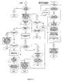
- FIG. 5 is a diagram showing the interaction and call hierarchy of the PEP algorithms.
- FIG. 6 is a diagram showing examples of the flow of data between logical groupings of PEP algorithms into the two main parts: TCP Emulator and FP Processor.
- FIG. 7 is a diagram showing the concept of the FP effective window mechanism comprising the FP effective receive window with its left and right edges.
- FIG. 8 is a flow chart of the Transmit TCP Emulator Algorithm.
- FIG. 9 is a flow chart of the Receive TCP Emulator Algorithm.
- FIG. 10 is a flow chart of the Transmit Flight Protocol Algorithm.
- FIG. 11 is a flow chart of the Receive Flight Protocol Algorithm.
- FIG. 12 is a flow chart of the Flight Protocol ACK Receipt algorithm.
- FIG. 13 is a flow chart of the Flight Protocol Transmit and Receive Buffer Algorithms.
- FIG. 14 is a flow chart of the Flight Protocol Send ACK Algorithm.
- FIG. 15 is a flow chart of the Flight Protocol Reset Algorithms.
- FIG. 16 is a ladder diagram showing the algorithm interaction and message flow for opening a connection over a satellite link involving the use of the FP and PEPs.
- FIG. 17 is a ladder diagram showing the algorithm interaction and message flow for closing a connection over a satellite link involving the use of the FP and PEPs.
- FIG. 18 is a transmit state diagram for the flight protocol showing the transmit states and transitions between these states of the Flight Protocol algorithms.
- FIG. 19 is a receive state diagram for the flight protocol showing the receive states and transitions between these states of the Flight Protocol algorithms.
- FIG. 20 is an illustration showing the effect of IPSec on TCP header.
- FIG. 21 is an illustration showing the problem encountered when using VPNs and PEPs.
- FIG. 22 is an illustration of the recommended solution for VPNs showing the proposed use of VPNs and PEPs simultaneously.
- FIG. 23 is a representation of the Flight Protocol packet structure.
- FIG. 24 shows a configuration of FP packet number and FP acknowledgement number for different acknowledgement types.
- FIG. 25 shows a FP data packet numbers acknowledged by different acknowledgement types.
- FIG. 26 shows an example of the generation of acknowledgement packets.
- FIG. 27 is a flow chart showing the procedure of the receipt of FP data packets and the generation of FP acknowledgement packets.
- FIG. 28 is a flow chart showing steps of the continuation of the acknowledgement generation algorithm.
- FIG. 29 is a flow chart showing steps of the continuation steps for the conversion to piggyback type of acknowledgements.
- FIGS. 30A & 30B are state tables for the transmit half of the flight protocol accompanying the transmit Flight Protocol state diagram.
- FIG. 31 is a state table for the receive half of the flight protocol accompanying the receive Flight Protocol state diagram.
- PEP 1 represents the behavior of a performance enhancing proxy (PEP) located at the gateway side of the satellite communication, in the case where data is being transferred from a server to a client.
- PEP 1 receives TCP packets and transmits FP packets.
- TCP emulator is the receiving endpoint of a TCP connection from the server.
- TCP Emulator converts the TCP/IP packets into FP packets.
- PEP 1 also handles the establishment and maintenance of a FP connection over the satellite link and the reliable delivery of FP packets to their destination: PEP 2 .
- PEP 1 's FP Transmit Buffer will store a copy of every single FP packet that is transmitted over the satellite link.
- PEP 1 will also retransmit or discard stored FP Packets on receipt of FP acknowledgements from PEP 2 .
- PEP 2 represents the behavior of a PEP located at the terminal side of the satellite communication, in the case where data is being transferred from a server to a client. It receives FP packets and transmits TCP/IP packets. The FP packets coming from PEP 1 are error checked and ordered before being forwarded to the TCP Emulator. PEP 2 sends FP acknowledgements to PEP 1 to instigate the retrieval of missing FP packets. If the received FP packets are not in order, they will be buffered in the FP Reassembly buffer until the missing FP packets are received. Once the missing FP packets are received, then the buffered FP packets can be retrieved in the proper order and passed to the TCP emulator.
- the TCP Emulator converts FP traffic into TCP/IP packets.
- PEP 2 also opens a standard TCP connection with the client and forwards the TCP/IP packets that it generates.
- the TCP Emulator has a TCP transmit buffer where it stores transmitted TCP/IP packets.
- the TCP Emulator is a functional element of a PEP. It transparently intercepts the standard TCP connection going from the server to the client (or vice versa). It manages the TCP connections as if it were the final end point of the transfer. It allows for the replacement of TCP over the satellite link with FP, the transport protocol of the invention, between the two PEPs.
- the role of the TCP emulator in a data transfer depends on a PEP's relation to the direction of file transfer. For a server-to-client transfer the TCP Emulator (in PEP 1 ) translates TCP/IP packets into FP packets. Then the TCP Emulator of the receive PEP (PEP 2 ) translates those FP packets back into standard TCP/IP packets and transmits them over a second TCP connection to their final destination.
- the Flight Protocol Processor is another functional element of a PEP. It manages the transfer of FP packets between PEPs and generates acknowledgements and re-transmissions of FP data packets. It receives FP packet shells, completes the empty FP header fields and transmits FP. It consists of Transmit and Receive algorithms, two buffers, and Send and Receiver Acknowledgement algorithms together with other sub-routines.
- TCP spoofing describes the process by which TCP packets belonging to a certain connection, or to many connections, are intercepted by a certain node along the way to the final destination. This node will behave like the TCP endpoint to which the TCP segments were destined. It will not forward those TCP segments to any other nodes and will generate local acknowledgements to the TCP connection Initiator.
- An “end-to-end connection” with PEPs going from the server to the client will consist of the following three connections:
- a FP Transmit Buffer is located in every PEP. A copy of every FP packet transmitted (e.g. over the satellite link) will be stored in this buffer and will remain in it until the FP acknowledgement packet (ACK) of the transmitted packet is received by the sending PEP.
- the FP Transmit Buffer will also store the time of transmission or retransmission of each packet. In the case where the ACK for a transmitted FP packet is not returned within a certain time, the FP packet will be copied from the buffer, retransmitted and the retransmission time updated in the FP Transmit Buffer.
- a time limit corresponding to the latest time that an acknowledgement for the transmitted or retransmitted packet should be received if the transmission was successful is made once. Comparisons to see whether an acknowledgement for the packet is overdue or not can be made directly to the stored value. Should the time of transmission or retransmission be stored directly, each time a comparison is carried out the round trip time and any other possible delays in the time between data transmission and acknowledgement reception must be subtracted from the current time. If a comparison is done more than once, the method of storing the expected acknowledgement arrival time will be more efficient. In any event, it should not be less efficient.
- the time and time values used may be related to a clock used anywhere in the system running in real or pseudo time.
- a FP Reassembly Buffer is located in every PEP. This buffer will store all the FP packets that have been received without corruption by a PEP (e.g. via the satellite link), but do not extend the effective left edge of the FP receive window. These packets are called out of sequence packets. Once the missing packets are received, the effective left edge of the window will be extended and the FP packets that fall between the old and new effective left edges of the window will be retrieved from the buffer and forwarded to the TCP Emulator. This buffer assures the contiguity of the sequence of packets passed for translation to the TCP Emulator.
- the FP receive window is a mechanism that indicates the state of the transmitted FP packets over the satellite link as seen by PEP 2 (the receiving PEP in our example). It shows which FP packets have been received and which have been lost.
- the window has a left edge and a right edge which change dynamically upon the arrival of FP packets at PEP 2 .
- Each edge corresponds to a certain FP packet number. Any packet number that is below the left edge, i.e. whose FP packet number is smaller than that of the left edge, is a packet that has been received and that has been forwarded to the TCP emulator. A number of holes will exist where packets have not been received. Packets received uncorrupted are stored in the FP Reassembly Buffer. Finally, FP packets whose packet number is higher than the right edge of the window correspond to packets that are either in flight or were not yet transmitted by PEP 1 .
- FP packets 1 , 2 , 3 , 5 and 7 are received by PEP 2 .
- the left edge of the window will be at FP packet number 4 , which is the first missing packet.
- the right edge of the window will be FP packet 8 .
- Packet 5 and 7 are stored in the reassembly buffer waiting for the arrival of FP packets 4 and 6 .
- Packets 1 , 2 and 3 are forwarded to the TCP Emulator and then to the communication endpoint.
- FP-packet number 4 Once FP-packet number 4 is received, then the left edge of the window will move to the next missing and expected FP packet, i.e. packet 6 . Packet 5 will be retrieved from the buffer and packets 4 and then 5 will be forwarded in order to the TCP Emulator. The right edge of the receive window will remain at packet number 8 until a packet with a FP packet number higher than 7 is successfully received.
- the FP Transmit Buffer stores every single FP packet that is transmitted over the satellite along with its time of transmission. If a packet is retransmitted, the time of retransmission is recorded. Re-stamping the packets is the process of updating the transmission time of a particular packet upon retransmission.
- a Grounded packet is a FP packet that has not been acknowledged and more than one Round Trip Time (RTT)+Epsilon has elapsed since its transmission (or re-transmission).
- RTT Round Trip Time
- Epsilon refers to the time taken by PEP 2 to receive and process the FP packet and to generate an ACK packet for it.
- Epsilon refers to the time taken by PEP 2 to receive and process the FP packet and to generate an ACK packet for it.
- An FP packet is the format of a TCP/IP packet that is using the Flight Protocol as its transport protocol.
- the Flight Protocol will be used over the large bandwidth-delay portion of the telecommunications link (i.e. the satellite link).
- PEP 1 will convert the standard TCP packet to a FP packet and PEP 2 will revert it back to a standard TCP packet.
- a FP hole refers to the case where a FP packet was not received at a PEP, creating a gap in an otherwise contiguous block of packets. The presence of a hole stops the progression of the left edge of the receive window until the hole is filled, i.e. the missing/delayed packet is received.
- a FP packet shell is a TCP packet that has been translated by the TCP Emulator of a PEP and is passed to the FP Processor Sections. It has the FP packet format but does not have all its header fields initialized, these are completed by the FP Processor.
- a TCP/IP packet is a TCP segment prepended with an IP header.
- a continuously running algorithm is a core algorithm that is shared by every Flight Protocol connection and is running continuously.
- An event driven algorithm is an algorithm that might be called by a certain Flight Protocol connection and that will affect that connection alone for a certain period of time.
- the Send ACK and Receive ACK algorithms are continuously running algorithms, but also have event driven sections in them.
- FIG. 2 shows how the network protocol stacks implemented in the PEPs and how they interface to the TCP.
- Each PEP 21 consists of a TCP Emulator 22 and a FP Processor 23 .
- the TCP Emulator 22 emulates a standard TCP connection to the external end user devices (client and server) and converts the TCP packets to FP packet shells. It also manages the flow of traffic to a satellite-specific transport protocol for use over the satellite connection, termed the Flight Protocol.
- the FP is a transport protocol that replaces TCP over the satellite link between a user terminal and a terrestrial/satellite gateway.
- IP addresses of the packet are preserved as the PEP passes the FP data packets to the gateway 24 or terminal 25 to be queued for transmission, before being sent over the satellite link.
- the combined PEP operation of the TCP Emulator and FP Processor are described below.
- FIG. 3 shows the PEP scheme, being an end-to-end satellite link with the PEPs, assuming that the Initiator 31 is on the gateway 35 side and the Responder 32 on the terminal 36 side.
- a TCP connection appears to the user to exist between the server and the client, however the satellite element of the link is enhanced by the use of PEPs at each entry point (PEP 133 at the gateway 35 and PEP 2 34 at the terminal 36 ).
- a PEP configuration can be used with more than one PEP device, in which case another, or other, PEPs may be situated in geographically distinct locations.
- the use of multiple PEPs in a communications system is known as a distributed PEP implementation.
- the PEP scheme itself is symmetrical in both directions, except that the return and forward paths use different capacity prediction algorithms.
- the return path algorithm uses measured Signal-to-Noise Ratio (SNR), the gateway received SNR (or power control adjustment) coupled with its requested/allocated slots and terminal queue status to determine the available return channel capacity.
- SNR Signal-to-Noise Ratio
- the TCP connection is split into three continuous communication links: two standard TCP connections interleaved by a FP connection.
- the gateway PEP (PEP 133 ) acknowledges and stores received TCP segments from the Internet Service Provider (ISP). This allows a standard TCP connection to exist between the server 31 and the gateway PEP (PEP 1 33 ), so as not to impact on the terrestrial network.
- the delay of the links between the gateway 35 and the server 31 are expected to be short, at least in contrast to the GEO satellite link delay.
- the server 31 sends TCP data to the client 32 over what appears to the server to be a TCP connection.
- the server 31 and the client 32 are unaware of the existence of the PEPs 33 and 34 in between them, which use the FP over the satellite 37 link.
- the gateway PEP (PEP 1 33 ) filters out TCP/IP packets and replies to the server 31 (using TCP ACKs) as if it were the client 32 .
- the gateway PEP (PEP 1 33 ) produces packets suitable for transmission over the satellite 37 link (FP Data Packets) and forwards the packets to the gateway 35 to be queued for transmission.
- a TCP three way handshake is not implemented over the satellite portion of the link: as soon as TCP/IP data carrying packets arrive at PEP 1 33 they are converted to FP packets and sent.
- the TCP connection that exists between the server 31 and PEP 1 33 increases transfer rate very quickly due to the low terrestrial delay and quasi error free (QEF) bit error rate (BER).
- the server 31 continues to send TCP/IP packets until completion of the requested data transfer.
- the gateway 35 is forwarding information concerning capacity on both the forward and return channels to capacity prediction algorithms.
- the signal-to-noise ratio (SNR) conditions are fed from other reference terminals (not shown) co-located at the gateway to the ‘Capacity Prediction Algorithm’.
- the said algorithm estimates the available forward channel throughput given the prevailing traffic and BER conditions.
- the Flight Protocol (FP) Transmit Processor 38 a of the gateway PEP (PEP 1 33 ) now governs the transportation of data over the satellite 37 . It uses the FP and allows the maximum use of bandwidth (BW) by not using techniques such as the Transmission Control Protocol (TCP) congestion control algorithms (Slow Start and Congestion Avoidance) and eliminating the TCP three-way handshake. For example if 10 Mb/s is available in the forward direction then the transfer rate (from gateway PEP 33 to terminal PEP 34 ) is set to 10 Mb/s. Furthermore if the available capacity changes then the applied data rate changes accordingly.
- TCP Transmission Control Protocol
- the PEP i.e., the TCP Emulator 39 a
- the rate of conventional TCP ACKs sent from the PEP to the TCP traffic origin the server 31 in the case of the gateway PEP 33 .
- data now flows in the forward direction to the terminal 36 , which in turn forwards the FP packets to the terminal PEP (PEP 2 34 ), which translates to TCP/IP packets and sets up a TCP connection to the end user device (the applicable client 32 ).
- the transmission from the terminal PEP 34 to the client 32 employs TCP so as not to impact the end user's choice of equipment (i.e. they can hurt purchase standard hardware and software).
- a FP Reassembly Buffer 40 b is used in the terminal PEP 34 , such that FP packets may be reordered first and then transmitted as TCP/IP packets, in the correct order, to the client.
- gateway PEP 33 all the dispatched FP packets (from the queue) are also stored in a FP Transmit Buffer 40 a and marked with the transmission time. This ensures that they are ready for retransmission in case a timer expires or an ACK for a packet with a higher FP packet number arrives to the gateway PEP (PEP 1 33 ), indicating a transmission loss.
- PEP 1 33 the gateway PEP
- the terminal PEP 34 receives FP packets, converts them to TCP/IP packets and forwards them to the client 32 , in substantially quicker time than compared to a single server to client TCP connection.
- the terminal PEP 34 sends FP ACKs in the return direction for each uncorrupted FP packet.
- the ACK generation scheme that FP employs could be classified as a selective acknowledgment scheme because it acknowledges the FP packets that are received after an FP packet that was discarded and whose packet number is higher than that of the discarded FP packet.
- the gateway PEP 33 On receiving FP packet ACKs from the terminal PEP 34 , the gateway PEP 33 discards the buffered FP packets from its FP Transmit Buffer 40 a because they are now acknowledged.
- the missing FP packets are copied from the gateway PEP Transmit Buffer 40 a and are re-inserted into the forward stream queue for transmission to the terminal. This is triggered either by a FP ACK arriving and PEP 1 33 determining that a packet, whose FP packet number is smaller than that of the received ACK, is still in the buffer 40 a .
- a FP ACK is received for packets 1 to 5 and 7 to 10 out of a 10 packet transmission.
- PEP 1 33 would check the buffer on receipt of FP ACK 7 and determine that packet 6 did not arrive successfully at PEP 2 34 .) Or after a timeout occurs at the gateway PEP 33 . A timeout occurs if no ACKs arrive in a given time and a PEP timer expires. To avoid needless retransmissions of packets an ‘in-flight/grounded’ concept exists. (‘In flight’ refers to packets that have been transmitted and could not have been acknowledged yet.
- the packet would be ‘in-flight’ until 800 ms had elapsed and ‘grounded’ thereafter.
- RTT round trip time
- a duplicate of it is stored in the FP Transmit Buffer 40 a with the transmission time.
- a FP packet is retransmitted, it is tested to see if it is ‘in-flight’ or ‘grounded’ by comparing the current time with its transmitted time and an RTT measure. Provided it is ‘grounded’ it is retransmitted and the new transmission time is updated in the buffered copy.
- PEP 1 33 When receiving a FP ACK for a retransmitted packet, PEP 1 33 (at the gateway) should delete the packet from its FP Transmit Buffer 40 a.
- UDP and IPSec User Datagram Protocol
- UDP and IPSec do not benefit from the performance enhancements that the PEPs provide. So as to avoid the PEP interfering with the behavior of any devices implementing quality of service in the end to end path, all packets (whether modified for acceleration or not) must leave the PEP in the order in which they arrived. In fact, unmodified packets may be subjected to a small absolute delay inside the PEP (i.e., PEP 1 33 or PEP 2 34 ), equal to the PEP processing delay, in order to avoid prioritizing this traffic over TCP traffic. The intended result is a zero relative delay between accelerated and non-accelerated traffic after exit from the PEP.
- the PEP can conceptually be broken into two major functional units, a TCP Emulator ( 39 a , 39 b ) and a FP Processor ( 38 a , 38 b ).
- the PEP 33 has two buffers, a FP Transmit Buffer 40 a and a FP Reassembly Buffer 40 b as shown in FIG. 4 .
- the PEP functional units might utilize underlying hardware, such as one or more network interfaces, one or more satellite interfaces, and an intercommunicating bus connecting memory and processor units.
- the Receive TCP Emulator 39 a in the gateway receives a TCP/IP packet containing a TCP segment, associates it to a TCP connection, acknowledges it and converts it to a FP packet shell.
- This shell has the remaining fields, such as the FP packet number and checksum, filled in by the Transmit FP Processor 38 a .
- the Transmit FP Processor 38 a determines if the packet can be sent by calling a capacity prediction algorithm and, provided there is sufficient capacity, passes the packet to the gateway or terminal for transmission. In addition, a copy of the FP packet is stored in the FP Transmit buffer 40 a .
- the terminal Receive FP Processor 38 b receives the FP packet and generates an ACK (using the FP ACK scheme) then passes it to the Transmit TCP Emulator 39 b (which, for the initial packet of a connection, sets up a standard TCP connection with the client).
- the Transmit TCP Emulator 39 b On receipt of a FP ACK at the gateway PEP 33 , the acknowledged FP packet is removed from the FP Transmit Buffer 40 a .
- the TCP Emulator 39 a converts the FP packet into a TCP/IP packet and sends it to the communication end point 31 . Once the TCP segment arrives at the real end point, a TCP ACK is generated and sent back to the terminal PEP 34 .
- PEP 33 and 34 filter all traffic by transparently passing all non-TCP and non-TCP related Internet Control Message Protocol (ICMP) and all encrypted TCP traffic around the TCP Emulator ( 39 a , 39 b ) and FP Processor ( 38 a , 38 b ) sections of the PEP, avoiding modification. All non-encrypted TCP/IP traffic is converted to FP packet shells by the Receive TCP Emulator 39 a , which passes these FP shells to the Transmit FP Processor 38 a to be completed by filling in the FP packet number and the FP Cyclic Redundancy Check (CRC).
- CRC Cyclic Redundancy Check
- the only exception to this rule is a subset of TCP-generated Internet Control Message Protocol (ICMP) messages. This function may be performed by filtering out all the IP packets with an IP protocol field set to 6 (i.e. TCP) and selective filtering all IP packets with an IP protocol field set to 1 (i.e. ICMP
- ICMP traffic is filtered for specific message types and codes generated in response to TCP traffic.
- the TCP Emulator ( 39 a / 39 b ) performs the processing of ICMP messages.
- this shows FP Transmit buffers 40 a as used in the FP transmit section 42 a of the PEP 33 to store copies of all transmitted FP packets in order to facilitate retransmissions, thus ensuring reliable delivery.
- the FP Receive Processor section 38 a of the PEP 33 has a reassembly buffer 41 a used to reorder/reassemble the FP data stream in the case of missing or corrupted FP packets.
- the TCP Emulator section 39 a of the PEP 33 relies on the underlying TCP stack and its normal behavior to accomplish the tasks of reliable transmission and reassembly.
- the PEP 33 Also included in the PEP 33 are two delay units 44 a / 45 a that are used to apply an absolute delay, which will result in a zero relative delay to the traffic that is not processed by the PEP. Thus the unprocessed traffic won't be prioritized over the processed traffic.
- a delay is necessary for each time traffic is processed in each direction of flow, thus with paired PEPs 33 and 34 , there are 2 delays per direction of data flow.
- the traffic that goes through the PEP and is processed is comprised of TCP packets. If these delays were not there, traffic requiring the same class of service would not be treated fairly, for example User Datagram Protocol (UDP) traffic would always be prioritized over TCP of the same priority class when a Quality of Service (QoS) system is used.
- UDP User Datagram Protocol
- QoS Quality of Service
- any First-In, First-Out (FiFo) (QoS) mechanism susceptible to dropping packets as queues fill will consistently lose a disproportionate volume of any protocol's traffic that is delayed as opposed to a protocol's traffic receiving no delay. This behavior is clearly not acceptable if the PEP is intended, ideally, not to interfere with other systems.
- the Transmit FP Algorithm 51 calls the relevant Capacity Prediction Algorithm 52 to determine when and if to transmit a packet.
- the FP Transmit Buffer Algorithm 53 is called to store, recover (plus re-stamp) and delete FP packets; the re-stamping moves data from a ‘grounded’ state to any ‘in-flight’ state by stamping packets in the buffer with the time of retransmission.
- the Receive FP algorithm 54 calls the Send ACK algorithm 57 .
- the FP Reassembly Buffer algorithm 58 is called, either to store the received packet or retrieve previously received packets, where the new packet completes a contiguous sequence, before passing the block of data packets to the TCP Emulator.
- the FP ACK Receipt Algorithm 55 and FP Transmit Buffer Algorithm 56 are called from the FP Receive Algorithm 54 (to handle ACKs and delete acknowledged packets).
- both Send ACK 57 and Receive ACK 55 algorithms are spawned for each connection during setup and are alive and operational for the duration of the connection. For example, for a one-way data transfer from gateway ( FIG. 3 , 35 ) to terminal ( FIG. 3 , 35 ), an ACK Receipt algorithm 55 would be spawned at the gateway and a Send ACK algorithm 57 at the terminal.
- the job of these algorithms is to manage timers which re-send data (if no ACKs arrive) or re-send ACKs (if no data arrives).
- the TCP Emulator Receive Algorithm 60 is layered above a TCP/IP network stack and receives IP datagrams (with TCP and IP headers still intact) from the stack for translation to FP packet shells. Examples of how this might be done include, (1) through the use of the raw sockets interface available in certain operating systems, or alternatively, (2) through a customized TCP/IP stack.
- the TCP Emulator Transmit Algorithm 59 receives FP packet shells and reformats them to pass a TCP/IP packet to the modified TCP/IP stack.
- Both these algorithms are operational for all the TCP connections they are interfacing with, as opposed to a copy being spawned for each connection, since the TCP stack and the PEP algorithms manage state information for the TCP and FP connections, respectively.
- the TCP Emulator algorithms 59 and 60 simply act as translators from TCP to FP and vice versa. The translation covers both the packet itself and the in-band control and signaling for such events as new connections and closing or aborting a connection.
- the TCP Emulator In order to be able to split the end-to-end TCP connection into three parts (TCP-FP-TCP, so that a satellite optimized transport protocol may be used) and still have the appearance of one end-to-end TCP connection, the TCP Emulator must function as both a TCP endpoint and a protocol translation unit. Two concepts, as mentioned earlier, are transparency to the end user and performance enhancement. Transparency dictates that the TCP Emulator should behave as if it is a TCP endpoint.
- the TCP Emulator consists of two distinct algorithms, the Receive Emulator Algorithm 60 and the Transmit Emulator Algorithm 59 .
- Receive and Transmit nomenclature is from the perspective of TCP received and transmitted; the Transmit Emulator Algorithm 59 and Receive Emulator Algorithm 60 emulate the transmit and receive sides of the TCP connection respectively.
- the TCP Emulator's two algorithms are part of a modified FP-TCP/IP stack and are used to interface TCP to FP and vice versa.
- the IP layer will check the checksums of received datagrams and reassemble fragments if necessary.
- the Maximum Segment Size (MSS) of the FP packet will be equal to the Maximum Transmission Unit (MTU) of the TCP packet minus 40 bytes, independent of whether the TCP segment got fragmented by the IP layer or not. Datagrams for any destination address will be examined by the PEP as it must intercept all traffic.
- the IP layer need not perform many of the routing tasks performed by standard IP layers as the IP headers and options are passed end to end, unmodified over the satellite hop. The IP layer must, however, be able to forward TCP/IP packets to both the terrestrial network and the satellite network.
- the TCP layer provides the standard mechanisms for opening a TCP connection, closing a TCP connection, resetting and sending data. These functions will need to be modified to take the full socket pair rather than just the foreign socket as the PEP is effectively ‘spoofing’ the source IP address for all connected systems. These functions will wrap the actual TCP/IP stack functions and add extra functionality, such as allowing data to be sent on synchronize packet (SYN) and finish packet (FIN).
- SYN synchronize packet
- FIN finish packet
- the TCP Emulator Algorithms consist of a Received algorithm and Transmit algorithm.
- the Receive TCP Emulator algorithm 60 in the context of the overall PEP, is shown in FIG. 6 , and the algorithm flow chart is shown in FIG. 9 .
- the receive TCP emulator calls for the TCP/IP packet in step 91 .
- receives incoming TCP/IP packets (with headers intact) passed up from the modified TCP stack.
- the algorithm converts incoming TCP traffic to outgoing FP packet shells as follows.
- a TCP/IP packet is received at the Receive Emulator Algorithm 60 from the modified TCP/IP network stack.
- step 94 If the packet contains no user data or SYN, FIN or Reset (RST) flags, i.e. it is a pure TCP ACK, then in step 94 it is discarded. Otherwise, in step 95 , the ACK flag is cleared, i.e. zeroed, signifying the TCP ACK number field is not valid and allowing reuse of the TCP ACK flag by the FP.
- the TCP Urgent Pointer field is then copied over the TCP Window Size field in step 96 to allow space for an extended and improved error detection mechanism in the FP packets.
- step 97 the space for the 32-bit CRC (TCP Checksum field plus the TCP Urgent pointer field) is then zeroed in preparation for the CRC calculation by the FP processor.
- FP packet shells are then passed to the Transmit FP Processor in step 98 .
- the FP transmit algorithm ( FIG. 6 , 51 ) of the FP Processor ( 38 a / 38 b ) then calculates the CRC over the packet, including the FP header but not the Internet Protocol (IP) header, and stores it in the CRC field created by the TCP Emulator Receive Algorithm 60 .
- IP Internet Protocol
- the Transmit TCP Emulator Algorithm 59 in the context of the overall PEP, is shown in FIG. 6 , and the algorithm flow chart is shown in FIG. 8 .
- Received FP packets are forwarded (after step 80 ) to the Transmit TCP Emulator Algorithm 59 to be converted to outgoing TCP/IP traffic.
- the Transmit TCP Emulator Algorithm 59 first, in step 81 , copies the contents of the TCP Window Size field into the TCP Urgent Pointer field.
- the reasoning behind this operation is to return the TCP Urgent pointer, which was stored in the TCP Window Size field by the TCP Emulator Receive Algorithm 60 , to its original position. This behavior preserves the value of the Urgent Pointer end-to-end for compatibility, while allowing a 32-bit contiguous space in the TCP header/FP header for a 32-bit CRC.
- step 82 a test is performed to determine if any of the FP SYN, FIN or RST flags are set.
- the FP SYN, FP FIN or FP RST packets trigger the Transmit TCP Emulator ( 39 a / 39 b ) to call the TCP stack's Open 83 , Close 84 or Reset 85 functions, respectively. It is assumed that the TCP stack used in an implementation will have functionality to allow for the opening of new connections, closing of connections and aborting of connections, said functionality being named Open 83 , Close 84 and Reset 85 respectively. If data is present in a TCP SYN at the originator 31 (FIG.
- Any FP packets without the SYN, FIN or RST flags set are assumed to be carrying data (all FP ACKs are not passed from the FP processor, like TCP ACKs from the TCP/IP stack) and are thus sent by calling the send function 86 of the modified TCP/IP stack.
- the underlying modified TCP stack buffers all the outgoing data until acknowledged, as usual.
- PMTUD Path MTU Discovery
- the specific action taken by the PEP is as follows.
- the PMTUD ICMP message is permanently removed from the traffic stream and PEP 2 34 reduces its Path MTU (PMTU) estimate prior to re-transmitting a data packet that is reduced in size to conform to this new PMTU estimate.
- PMTU Path MTU
- the ICMP message may either be ignored by that host or may cause some form of error. In all probability the TCP segment that triggered the error will have been successfully acknowledged by PEP 1 33 and discarded from the originating host's 31 TCP transmit buffer. It is therefore not possible for the host 31 to retransmit it. This may either cause the message to be ignored or trigger an error.
- PEP 2 34 will have to resize all future packets between its two interfaces to avoid fragmentation. Ignoring this ICMP message will only cause the system to fail if the Don't Fragment (DF) bit is set in the IP header as is required by the PMTUD mechanism. It is possible to ignore this ICMP Message if the DF bit is not set, but datagrams that are too large will then be fragmented possibly degrading system performance.
- DF Don't Fragment
- the ICMP Network Unreachable, Host Unreachable and Source Quench messages should be handled to provide more timely responses for errors and other problem conditions.
- the Network and Host Unreachable messages should be responded to in different ways depending upon the state of the end-to-end communication to which they relate.
- the Network and Host Unreachable messages should cause end-to-end connection tear-down under the control of the PEP for connections that have not been correctly established. For established connections, they should be treated as transient errors and a retransmission from the PEP receiving the message should be attempted.
- Connection tear-down is facilitated by the PEPs involved by the PEPs communicating TCP/FP reset packets to themselves and the end points to ensure the return to a known state without unnecessary delay, which may consume system resources.
- the reception of a Source Quench message by a PEP should trigger the TCP Emulator of that PEP to enter slow start as would be expected of an end host receiving that message.
- ICMP type Destination Unreachable codes: Source Route Failed, Destination Network Unknown, Destination Host Unknown, Source Host Isolated, Network Unreachable for Type of Service (ToS) and Host Unreachable for ToS.
- ICMP type Destination Unreachable codes Protocol Unreachable, Port Unreachable, Destination Network Administratively Prohibited, Destination Host Administratively Prohibited, Communication Administratively Prohibited by Filtering, Host Precedence Violation and Precedence Cutoff in Effect.
- the ICMP message type Parameter Problem, codes IP Header Bad and Required Option Missing messages should be handled by the PEPs as described for an end to end connection abort.
- ICMP type Time Exceeded, code TTL Equals Zero During Reassembly should trigger a retransmission. All other ICMP message types publicly known to this date should be ignored by the PEP and left to pass to their intended destination.
- the PEP(s) are handling TCP and FP connections for multiple IP addresses, it is not possible to associate the incoming packets to the correct connection using only the source IP address and the source and destination port numbers. For the TCP and/or FP connections it is, therefore, necessary to consider further information.
- One such choice would be the use of the destination IP address in addition to the aforementioned information. This would mean that the whole socket pair would be utilized to de-multiplex incoming packets to the correct connections, or in other words, de-multiplexing the connections.
- the FP of the invention is used over the satellite portion of the link with FP packets reusing certain fields in the TCP header.
- the IP header will be maintained and transported over the FP link.
- the FP header will replace the TCP header and will include flags for signaling connection initiation, termination, or ACKs.
- a single field in the FP packet header (part of the TCP Sequence Number field) is used to represent the number of the FP data packet or FP-ACK.
- a 32-bit CRC over the whole packet IP header, FP header and user data
- IP has a checksum on the header and TCP on the header and data, these are 16-bit and based on one's complement binary arithmetic.
- the Ethernet CRC (commonly used on both TCP end connections at the link layer) is based on binary division, which is significantly more robust, detecting many more errors due to the binary long division process that allows bit errors to propagate to more bits in the checksum than does binary addition. Additionally, the 32-bit length of the CRC also increases the number of errors that may be detected. The use of the PEPs and connection splitting should not adversely affect the end user experience by inserting a weak link in the end-to-end connection. For this reason, a 32-bit CRC has been chosen for the FP to help mitigate the increased chance of the user receiving data containing undetected errors due to the higher than terrestrial wire line residual BER of the satellite hop.
- TCP and some other protocols indicate the data packets they expect to receive by using a sliding window mechanism.
- This window can be thought of as a view of part of the data stream at a given point in time.
- Two commonly discussed concepts are those of the left and right edges of the window.
- the left edge of the window marks the beginning of the next data element (segment, packet, block or byte) that is expected at the receiver, i.e. the first data element expected, the data element with the lowest sequence number that is still outstanding (if sequence numbering is used).
- sequence numbering any packet that is to the left of the left edge has been received in order and transmitted by the TCP emulator.
- the right window edge marks the data element, after the buffered element with the highest number.
- the left edge is extended if a received element belongs at the left edge of the window, contiguous to the data already received. A hole is created if a non-contiguous segment is received.
- the Flight Protocol uses a window mechanism, shown in FIG. 7 for managing the re-assembly buffer.
- the window 71 starts with a left edge 72 of zero and a right edge 73 of 1.
- Flow control is via the capacity prediction algorithm, as instantaneous capacity is calculable for the satellite link (from known assignments) and does not involve the receive window 71 . Therefore the concepts of the FP receive window and the left and right window edges are essentially notional.
- the left edge 72 corresponds to the FP packet number of the left-most hole in the PEP re-assembly buffer 74 and the right edge 73 corresponds to the FP packet number above the buffered FP packet with the highest FP packet number.
- the receive window 71 is from the left edge to the right edge.
- the FP packet structure is shown in FIG. 23 .
- the FP header replaces the TCP header at the transport layer but a FP packet still contains the end-to-end rP header 231 to allow compatibility with (transmission through) systems between the two PEPs. Additionally, certain TCP fields must also be preserved for the PEPs and FP to remain compatible with end-to-end TCP.
- the TCP source 233 and destination 234 port numbers are preserved and used by both the TCP Emulator (in the TCP world) and the FP Processor (in the FP world) for identification of the connection to which packets belong.
- the FP Packet Number 235 replaces the TCP Sequence Number and is, as its name suggests, packet based as opposed to byte stream based. Analogously and necessarily, the FP ACK Number 236 is also packet based. Packet numbers (also used by FP ACKs) are monotonically increasing numbers that start from zero every time a new FP connection is opened.
- the TCP Header Length field 243 is recalculated by the modified TCP/IP in the TCP Emulator prior to transmission and is unused over the FP link.
- the TCP Reserved field 242 must stay unused for compatibility with TCP as its future uses are unknown.
- TCP uses 6 flag bits that are used as follows by the FP.
- the URG 237 (Urgent Pointer valid) and PSH 238 (Push Function) flags are unmodified by the FP, allowing communication of this information end-to-end for TCP compatibility.
- the TCP ACK flag is also used by the FP.
- the Receive TCP Emulator Algorithm clears this flag upon receipt of a TCP/IP packet. This allows the ACK flag to be set to 1, i.e. “On”, by the Transmit FP Processor if required for piggybacking a FP ACK.
- the SYN 240 , FIN 241 and RST 239 flags are used by the FP in much the same way as TCP uses them.
- the SYN flag 240 signals a new FP connection to the Receive FP Processor, the FIN flag 241 the end of a FP connection and the RST flag 239 to abort the current FP connection. By not modifying these flags end-to-end they trigger the appropriate behavior in each entity along the connection.
- a TCP SYN packet from the end point 31 triggers the Receive TCP Emulator 39 a and its modified TCP/IP stack to complete a TCP three-way handshake then the TCP packet is translated to a FP packet shell with the SYN flag 240 still set.
- the FP Processor 38 a detects the SYN flag 240 and opens new connection status information before sending the FP packet to the Receive FP Processor 38 b in the other PEP 34 .
- the FP Processor 38 b in the second PEP 34 then opens its connection tracking information and passes the FP packet to the Transmit TCP Emulator 39 b which requests a new TCP connection from the modified TCP/IP stack, completing the end-to-end connection.
- the TCP Urgent Pointer field 232 is moved but its value preserved (for compatibility). A 32-bit contiguous space is then created for the insertion of a 32-bit FP Cyclic Redundancy Check (CRC) 244 . All TCP options are removed over the FP link as they are specific to each terrestrial connection.
- CRC Cyclic Redundancy Check
- the treatment of loss by the Flight Protocol is different to that of TCP which assumes that losses are due to congestion. Although this may be a fair assumption on a terrestrial link it is not so over a GEO satellite. Therefore, the Flight Protocol assumes that all losses are due to errors. Also the Flight Protocol de-couples the reliability and flow control mechanisms by not using incoming ACKs as a count of the number of packets to have left the network. This de-coupling of reliability and flow control allows the use of alternative ACK schemes, which may be optimized for efficiency of channel utilization or other reasons.
- the packet is stored in the PEP's FP Transmit Buffer 40 a ( FIG. 3 ) with a time stamp based on the current network clock.
- the timestamp may be calculated to be equal to the time of transmission, as per the network clock, plus the maximum time (limit) for an ACK for that packet to arrive back at the sender.
- the rationale for this system is to ensure that consecutive FP ACKs following a missing FP ACK do not trigger multiple replacement packets being sent. Multiple ACKs would have naturally occurred because a replacement packet will not be noted at the sender for one round trip time (RTT) and during this time the receiver may continue to flag a missing packet.
- RTT round trip time
- a typical transfer of data would occur as follows, starting with the point where the TCP/IP data packet sent by the server is received by PEP 1 33 ( FIG. 3 ) and converted into a FP packet. Then the FP packet is copied into the FP Transmit Buffer 40 a and the original transmitted. After a time equal to the RTT over the satellite link (including time to allow for system processing, ACK timer delays, queuing), the FP packet state in the buffer 40 a becomes grounded, meaning that enough time has elapsed for the packet to reach its destination and an FP ACK to have returned.
- PEP 1 33 The fact that a FP ACK has not been received by PEP 1 33 implies one of two things: either the FP packet did not reach its destination (PEP 2 34 ), including being received but in error (i.e. a corrupt packet was received), or the resulting FP ACK was lost or corrupted in the return direction.
- the FP packet must, therefore, be copied from the FP Transmit Buffer 40 a and retransmitted over the satellite link 37 .
- the buffered retransmitted FP packet is again time-stamped in the FP Transmit Buffer 40 a with the time of retransmission and marked as “in-flight”.
- the packet in the buffer is considered “in-flight” as long as the current network clock time did not exceed the RTT plus time stamp in the buffer, or in the case of pre-calculating the expected ACK arrival time, did not exceed the stored time value.
- the sending PEP detects a missing packet by receiving an acknowledgement out of order. For example it receives acknowledgements for packets 1 - 5 and 7 - 10 but not 6; on receipt of the FP ACK for packet 7 it will check if packet 6 is still in the buffer and ‘grounded’. If both these conditions are met the packet is re-transmitted and the packet state in the buffer is time-stamped and reset to in-flight.
- PEP 1 33 will then automatically re-transmit all unacknowledged and ‘grounded’ data.
- PEP 2 34 will then automatically retransmit the FP ACK of the last uncorrupted FP packet that it received and that corresponds to the silent connection. This FP ACK will cause a scan through the FP Transmit Buffer 40 a of PEP 1 33 for packets that are grounded and that correspond to the same connection as the received ACK packet. If such packets exist, then copies will be retransmitted from PEP 1 33 to PEP 2 34 .
- the FP ACK scheme described is implicitly a Selective Acknowledgement Scheme. Packets can be acknowledged independently or as multiple packets. Note that after several attempts after time-outs as described in (2) and (3) above, the connection will be shut down.
- Flight Protocol Algorithms involved as part of the invention's system and method consist of Transmit Flight Protocol (TX FP) & Transmit buffer (TX Buffer) Algorithms.
- TX FP 51 and TX Buffer Algorithms (B, C 1 , C 2 , C 3 , C 4 ) are shown, in the context of the overall PEP algorithms, in FIG. 6 , and the algorithm flow charts are given in FIG. 10 .
- the algorithms C 1 to C 4 are shown in FIG. 13 .
- the FP traffic (multiple data packets) originating at the Receive TCP Emulator then passes to the Transmit FP Algorithm 51 (assuming capacity is available) where it is stored by the FP Transmit Buffer Algorithm, C 1 , in order to guarantee reliable transmission.
- the FP packets are then passed to the gateway or terminal to be queued for transmission.
- the Send ACK algorithm, B denoted TX ACK, is called upon receipt of FP packets by the Receive FP Algorithm 54 to Transmit FP ACKs back to the sender.
- Receive FP 54 and Receive Buffer Algorithms (A, D 1 , D 2 , D 3 ) are shown in the context of the overall PEP algorithms, in FIG. 6 and the algorithm flow charts are given in FIG. 11 and the algorithms D 1 to D 3 of FIG. 13 .
- Received FP packets are handled by the Receive FP Algorithm 54 .
- Algorithms D 1 (calculate left edge) and D 2 (reassembly buffer management) handle the determination of the left edge of the effective window (see also FIG. 7 ) and the reordering of packets retransmitted and received out of order (because of packet loss/corruption).
- These algorithms manipulate the FP Reassembly Buffer 48 b (FIG. 3 ), which is distinct from the FP Transmit Buffer 40 a .
- Incoming FP data packets trigger the Send ACK Algorithm (B) described earlier.
- Incoming FP ACKs trigger the Receipt of ACK Algorithm marked as RX ACK (A).
- C 2 , C 3 and/or C 4 are called.
- PEP 1 33 For each new connection that is created, two continuously running algorithms are spawned at each PEP. These are the system's Connection Management algorithms.
- PEP 1 33 spawns an FP ACK Receipt Algorithm (continuously running), shown in FIG. 12 , which re-sends missing packets, based on a timer, if no FP ACKs arrive. This timer is reset upon ACK arrival and expires when no ACKs have arrived in a given interval since being reset. Upon timer expiration, all packets that have been sent and are grounded (considered to have had sufficient time since transmission to allow an ACK to arrive back at the sender) but unacknowledged are retransmitted. Likewise a FP RESET and TCP RESET are sent in the applicable directions at the expiry of a global timer as shown in FIG. 15 .
- a continuously running FP Send ACK Algorithm 57 (FIG. 5 ), shown in FIG. 14 , is spawned. This generates ACKs if no packets are arriving and eventually, if necessary, a TCP and FP RESET in applicable directions following the occurrence of a global timeout. The specific action taken upon expiration of the timer is the transmission of an ACK for the last packet successfully received.
- the triggering values of the two above-mentioned timers, the one for re-sending missing packets and the one for re-sending the last ACK, should be different to avoid the mechanisms triggering needlessly (i.e. when the other mechanism is already being used). This difference may take into account the time in flight and processing delays at the sender and receiver from both the ACK and data packets perspectives. Setting the value of the first timer described above to be smaller than the second timer described above is to be preferred.
- FIG. 16 shows the interaction of, and exchange of packets between, algorithms in the transfer Initiator (gateway PEP 1 33 ) and the transfer recipient (terminal PEP 2 34 ).
- the TCP Emulator 39 a opens the ‘TCP connection tracking’ 162 , the continuously running FP ACK Receipt Algorithm 166 is spawned and then sends a FP shell, with the SYN flag set, to the FP Transmit Algorithm 167 which opens ‘FP connection tracking’ 163 .
- a FP packet is generated and sent to the terminal PEP 34 which in turn opens its ‘FP connection tracking’ 164 , calls the ‘FP Send ACK’ Algorithm 168 and forwards the FP shell, with SYN flag, to the terminal PEP TCP Emulator 39 b .
- a continuously running FP Send ACK Algorithm is spawned.
- a TCP connection to the end host (not shown) is now established as well as ‘TCP connection tracking’ 165 in the Emulator 39 b.
- the originating (client initiated) TCP connection is allowed to complete its three way handshake, and data (HTTP requests are one possibility) can start to be transferred from the client to PEP 2 34 . This saves time as data can be transmitted between the PEPs, arriving soon after the initial FP SYN packet, without the delay associated with the three way handshake.
- the first data packet is received at the TCP Emulator 39 a of the gateway PEP, it is translated to FP and forwarded via the satellite, even if the first FP packet with SYN has not been acknowledged.
- the connection opening does not use a pre-data handshake or pre-data agreement mechanism of any form.
- the terminal PEP 34 will start receiving data packets for a connection that it thinks does not exist. Under these circumstances a FP RESET will be sent back (see FIG.
- FP packets with SYN flags set are acknowledged as if they were normal FP data packets. The handshake (occurring alongside data transfer) is considered finished when the original FP packet with SYN is acknowledged successfully.
- this mechanism may interfere with the end-to-end behavior of certain applications and, as such, it would be sensible to offer either a user controlled or automatic mechanism whereby a connection that fails to setup end-to-end will be run in an end-to-end setup mode driven by the TCP end points.
- the failure of a connection to setup end-to-end correctly the first time should default the PEP whose TCP Emulator initializes that connection to mark the associated IP address (and possibly port numbers also) as requiring safer setup processing. It is then necessary for the PEP to communicate this information to the other PEP to force an end-to-end connection setup.
- the ability for the user to choose at any point through a user interface the use, or not, of an end-to-end connection establishment would also be a useful feature in this context.
- Case 1 shows the normal operation where, after the transportation of a FP shell with FIN and receipt of all data packets at the terminal PEP 34 , the gateway PEP TCP Emulator connection 171 and terminal PEP FP connection 172 are closed. The closure results in ‘connection tracking’ information being deleted. Assuming all data has been received and acknowledged the terminal PEP 34 acknowledges the FIN. This triggers the closing of the gateway PEP FP 173 . In addition the FP packet shell with FIN is passed to the terminal PEP TCP Emulator 39 b which completes the overall half close 174 .
- TCP uses a concept of a half close where one direction of the full-duplex TCP connection is closed for the purposes of transmitting data.
- the invention's FP uses a different model where in fact, two separate simplex FP connections are established and each may be torn down independently, effecting a half close in the FP world.
- connection closure we refer to the connection closure as a ‘half close’ since from a TCP point of view the connection has only been closed between the server and client (i.e. in the gateway-terminal direction). From a FP perspective, the connection is closed as two independent FP one-way connections (which are run as if one duplex connection) to support an end to end TCP connection (one of them now closed).
- Cases 2 - 4 of FIG. 17 represent situations whereby a RESET is required. This could be either a TCP originated RESET (as in case 4 ) or a FP RESET triggered by a timeout due to lack of packets or ACKs. Cases 5 and 6 of FIG. 17 are special cases that ensure a robust system; for example, if replacement data for a connection that the receiver has no knowledge of (‘Connection Tracking’ information exists) arrives, a RESET is triggered. If an error condition occurs, it is important to ensure that the system remains stable. Therefore, a RESET marked packet should trigger at either PEP the propagation of RESET marked packets to all other entities involved in the connection.
- a PEP receiving a RESET from the terrestrial world should forward the FP packet with RESET to the other PEP and that PEP should pass the packet to be converted to TCP and sent out over the other terrestrial link.
- a FP processor generates a RESET in response to some error event, that RESET packet should be forwarded by the other (receiving) PEP to the connected terrestrial endpoint.
- the FP Processor (i.e., FIG. 3 , 38 a / 38 b ) side of the PEP is responsible for sending and receiving data reliably across the satellite link. Due to the special characteristics of this link, most notably the large bandwidth-delay product and the relatively large in-transit error probability, the Flight Protocol is substantially different from TCP, which is used over the terrestrial part of the overall connection.
- FIG. 18 relates to the transmit section of a PEP (i.e. PEP 1 33 in a data transfer from server to client).
- FIGS. 30A and 30B show the corresponding state table for the transmit half of the FP. Initially, the system is in the Idle state 181 , awaiting for something to transmit, either data or an ACK message.
- a number of packets are created, then passed to the gateway or terminal for queuing and transmission, and the Outstanding packets/Window open state 182 is entered.
- a packet which has been transmitted but for which no ACK has been received yet (because of the RTT) is called outstanding (in-flight) data.
- An outstanding packet becomes unacknowledged when its has been transmitted for more than a RTT and the packet is still not acknowledged (grounded data).
- a packet that remains unacknowledged for too long becomes timed-out (and will be retransmitted).
- a timestamp based on the network clock is also recorded. Until this timestamp expires, the data is assumed to be in-flight. Once the timestamp expires, the data is said to be grounded and if no ACKs have been received, a retransmission is required. Any ACKs received indicating loss of the packet, while the packet is in the in-flight state, must be ignored to prevent multiple unnecessary retransmissions of a packet.
- the system remains in the Outstanding packets/Window open state 182 , where transmission of new packets is allowed.
- the flight timer expires for some of the transmitted packets and the system moves to the Unacknowledged packets/Window open state 183 . Transmission is still allowed but now ACKs are expected for the grounded packets.
- FIG. 19 shows the state diagram for the Receive (RX) section of the FP processor. In previous examples these relate to PEP 2 34 (see also FIG. 3 , 38 b ).
- the states relate naturally to the status of the FP Reassembly Buffer 416 . State transitions are based on processing a single packet at a time.
- FIG. 31 lists the conditions that trigger state changes for the RX half of the FP, as well as actions associated with state transitions.
- the system is initially in the Receive buffer empty state 191 , and remains in this state until new (as opposed to already received) data is received. If a packet of new data is received and the packet extends a contiguous sequence starting from the next expected packet, the system moves to the No holes state 192 . From the No holes state 192 , the receiver will send back an ACK, deliver data to the TCP Emulator and move the left edge of the receive window past the last received packet. When all the received data in the buffer is delivered to the TCP Emulator, the system returns to the Receive buffer empty state 191 . Reception of a new packet that extends the data sequence without holes keeps the system in the No holes state 192 . The correct new packet is acknowledged, and will be delivered to the TCP Emulator.
- Receiving a new packet does not necessarily result in data delivery.
- a received packet may, for instance, create a new hole further down the received sequence. Reception of a data packet that completely fills a hole may allow the delivery of data to the TCP Emulator, either partial if the leftmost hole of several is filled, or complete in case a single hole is filled by the received packet. In the latter case, the system moves to the No holes state 192 .
- a received data packet it is also possible for a received data packet to partially fill a hole that spans more than a packet. Partial data delivery will then be possible only if the packet extends the already received sequence (an extension of the left edge of the receive window). Otherwise, the hole topology of the received sequence remains the same and no data delivery is possible.
- a network clock is also provided for time stamping buffered FP packets using a satellite-wide clock.
- the time stamps are used to monitor the in-flight and grounded status of transmitted FP packets.
- the timestamps may however be based on any clock or counter in real or pseudo time with fine enough resolution.
- a Virtual Private Network combines the advantages of private and public networks by allowing a company with multiple sites to have the illusion of a completely private network, while using a public network to carry traffic between sites.
- the ‘illusion’ is created by the use of tunnels to connect private realms, through a public network system.
- a VPN hence provides network-to-network or remote-user-to-network connectivity via an encrypted tunnel through the public Internet.
- the two key issues in a VPN are tunneling (the masking/hiding of the payload and addresses) and security (the ability to encrypt the contents of the payload). These two concepts are briefly introduced below.
- the security inherent in a VPN has some negative impacts, most noticeably in a network with large bandwidth-delay products and a mixture of Private and Public EP addressees, such as a satellite environment. In particular the use of PEPs and NATs (Network Address Translators) is limited.
- Tunneling is the ability to create circuit-like connections across a packet-oriented Wide Area Network (WAN) topology.
- a tunneling protocol must encapsulate each source network packet into a new packet that contains the connection management intelligence necessary to set up, tear down and manage the tunnel.
- An effective tunnel mechanism hides the networking data in addition to the application and payload layers.
- tunnels there are two approaches to establishing tunnels: a “CPE-based approach” (Customer Premises Equipment) and a “network based approach”.
- CPE-based approach Customer Premises Equipment
- network based approach In the first approach, tunnels are established only between the CPE devices, whereas in the second approach tunnels are also established between the routers of the core non-private network.
- IPSec in a broad sense, is the ability to encrypt the packets so that they cannot be accessed and/or understood by unauthorized users.
- IPSec In recent years the emerging IPSec standard has become the international standard for Virtual Private Networks. Indeed many articles state that IPSec is a requirement for an effective VPN.
- IP network
- IPSec is a suite of protocol standards aimed at providing security services at the network (IP) layer. It can provide host-to-host, host-to-network and network-to-host protection, independently of network topology. Being applied at the IP layer, upper layers are protected transparently.
- IP network
- IPSec relies on two main security protocols dealing with protection of traffic:
- ISAKMP Internet Security Association and Key Management Protocol
- IKE Internet Key Exchange
- a Protected host sends clear traffic to VPN equipment (the source device) located at the point of connection to the public network.
- the source device examines the data according to rules specified by the network manager, securing the information or allowing it to pass unaffected.
- the source device encrypts (encodes) and authenticates (through a digital signature or a keyed hash) the whole packet, including the transmitted data as well as the source and destination host IP address.
- the source device then attaches a new header to the data, including information that the destination device requires for security functions and process initialization.
- the source VPN kit then encapsulates the encrypted and authenticated packet with the source and destination IP addresses of the destination device, or devices. This results in a virtual tunnel through the public network.
- tunneling to create a virtual channel
- encryption to secure data
- IPSec Internet Protocol Security
- IPSec usually introduces negative ‘side effects’ in GEO satellite multimedia services.
- the key issue is the hiding of the TCP header by IPSec (see FIG. 20 ).
- IPSec is incompatible with the use of PEP performance enhancements.
- PEPs that are implemented on intermediate nodes in the network cannot examine the TCP headers of IP packets because encryption of the IP packets using Encapsulating Security Payload (ESP) (in either transport or tunnel mode) renders the TCP header and payload unintelligible to the PEPs. Without being able to examine the transport headers, a PEP may not function at all.
- ESP Encapsulating Security Payload
- AH Authentication Header
- the PEP implementation may not be able to function in the presence of IPSec. For example, it is difficult to do ACK spacing if the PEP cannot reliably determine which IP packets contain ACKs of interest
- FIG. 21 gives an overview of a typical satellite network configuration with a VPN implemented between a remote user 210 and a head office 212 .
- the encrypted tunnel 214 between the two VPN points ( 211 , 213 ) renders intermediate PEPs ( 215 , 216 ) and the intermediate gateway-based Network Address Translator (NAT) 217 powerless.
- NAT Network Address Translator
- packets are encapsulated between user spaces (i.e. traveling over encapsulated space and other users' space).
- the recommended solution is to split the encapsulation so that user's space exists at the ISP that manages the VPN (allowing the reading of TCP headers and thus the use of NATs, PEPs and other functionality).
- FIG. 22 shows the inventive solution.
- the PEP and NAT are included in the POP (Point of Presence) 222 , located between the Terminal 221 and Host/LAN 223 .
- the first PEP (at the Gateway, not shown) deals with all non-VPN packets (anything that is not encoded). This is typically traffic (multiple data packets) generated by the commercial terminal.
- the second PEP is located at the ISP 226 that manages the VPN, with a dedicated link running between the Gateway 227 and ISP 226 (meaning traffic that is not governed by ‘conservative’ mechanisms, in order to prevent congestion collapse, is not released onto the Internet).
- VPN termination occurs at the ISP, which has access to the IPSec Security Association and can now employ PEPs, NATs and other functionality.
- a requirement that is thought to be peculiar to this approach is the need for some kind of dedicated link or capacity across any public network between the PEP equipment or software and the satellite link. This requirement applies irrespective of whether the PEP is placed across a public network from a terminal or a hub.
- the dedicated link or capacity may take one of many forms, possibly taking different forms simultaneously in different sections of a given system. Examples of dedicated capacity or links may be an isolated physical link from the PEP, across any public network, to the satellite link or a fixed capacity virtual circuit or similar logical partitioning of capacity.
- a capacity with a fixed upper bound may also be used as opposed to the use of a fixed capacity, the difference being that a fixed upper bound, while still bounding the maximum data rate, allows use of unused capacity by other traffic not related to the PEP.
- the rationale for this scheme is that the PEP and its traffic are not suitable for public networks because the traffic does not follow what is often known as conservative algorithms for injecting traffic into the network. Allowing this sort of traffic onto public networks would likely cause severe damage to network stability.
- any form of this proposed solution it is necessary to have the boxes performing PEP, NAT and VPN functionality in a particular order.
- the VPN devices must be nearest together at the ends of a particular link or encrypted tunnel. This is because the NAT and PEP devices cannot perform their functions on encrypted traffic.
- Next to the VPN boxes should be placed the PEP boxes to provide the traffic acceleration on the plaintext (unencrypted) traffic.
- On the outside of the PEP boxes may be located NAT boxes as the NAT boxes may need to modify the transport layer depending upon the type of NAT in use. NAT boxes are not required at both ends.
- PEPs should not adversely affect a system's vulnerability, i.e., the security, resistance to attack or robustness and reliability of systems attached to or using the PEP(s). There are two distinct mechanisms by which system vulnerability could occur.
- the PEP may weaken security or attack resistance features already included elsewhere in the system. For example if the TCP Emulator of the PEP does not implement secure initial sequence number generation, an attacker may establish a spoofed connection to the PEP through a sequence number guessing attack which the PEP, or a second PEP in a distributed scenario, would then connect to the intended target. If the PEP were not present the attack would have failed on the intended target but due to the PEP's presence an attack was facilitated. Thus the PEP can be said to directly weaken available protections if such features are not included.
- the second mechanism by which a PEP may become a security risk is through its placement and use in a system.
- a Denial of Service (DoS) attack such as a SYN flood attack
- DoS Denial of Service
- SYN flood attack both the hosts would potentially be affected. This would occur because the PEP, as the TCP connection terminator, would become the target of the attack by proxy so as to speak.
- the attack would affect the target end system by affecting the PEP, but would also affect all other untargeted connected hosts.
- the inventive enhanced PEP may be combined with mechanisms to prevent or minimize the impact of such attacks, thus protecting its clients or hosts from such attacks. Not only should the PEP include the standard TCP mechanisms to resist attack, such as secure initial sequence number generation, which may be expected, but also the PEP should include additional features such as, for example, methods to mitigate SYN Flood attacks, fragmentation attacks, the undesirable effects of port scans and any other attacks that commonly occur on the TCP stack.
- the invention's PEP may be used with a mechanism whereby the TCP MSSs advertised, by the TCP Emulators of the PEPs, to the real communication endpoints are chosen so as to fully utilize an integer number of the fundamental lower layer payload data units.
- lower layer fundamental data units what is meant is usually the link layer data unit or any other unit that is often the unit of retransmission.
- This method may also take into account that link layer payloads encapsulating a single IP datagram may be of differing sizes, for instance the last payload may be smaller due to the inclusion of an error detection code, e.g. a CRC.
- This method would typically include calculating the additional overhead from TCP and IP headers (usually 40 bytes) and using an MSS to the real end point that would both avoid fragmentation on the terrestrial link but also occupy fully a whole number of link layer payload units in the link between the PEPs.
- This technique may be used to optimize the efficiency of the system over Asynchronous Transfer Mode (ATM), Motion Picture Experts Group (MPEG) or similar link layers. Normally the maximum MSS resulting in an MTU conforming to PMTUD and also filling exactly a number of link layer payloads would be chosen.
- ATM Asynchronous Transfer Mode
- MPEG Motion Picture Experts Group
- the enhanced PEP of the invention needs very little configuration at installation.
- the enhanced PEP itself will not require pre-configuration with information describing addresses of the attached devices. By this, it is meant that unlike other available products, this novel PEP itself will not need entering into it the addresses of directly connected entities or networks or those entities expecting to receive performance enhancement.
- Authorization for network use will be handled in other subsystems in the hub(s) and terminals as necessary and the PEP(s) will simply attempt to accelerate all TCP connections arriving at their terrestrial interfaces.
- the PEP is able to intercept and terminate incoming TCP connections, originate and terminate a second connection (which may be a different protocol) over the satellite portion of the end-to-end connection, and also originate the second terrestrial TCP connection, all without the need for pre-configuration of addresses at the PEP.
- These addresses which are not pre-configured, may be IP addresses or other equivalent uniquely identifying addresses.
- the invention's Flight Protocol alternative acknowledgement (ACK) scheme was designed to reduce the return link 11 (inbound to the gateway) overhead traffic used to acknowledge FP data packets flowing on the forward link 12 (outbound from the gateway).
- the return link traffic consists mainly of FP ACK packets and sometimes of FP data packets.
- the ACK scheme uses three different types of ACK packets, shown in FIG. 24 , to acknowledge a large and variable number of FP data packets per ACK packet. All ACK packet types have a bitmap of a fixed length that acknowledges FP data packets as well as an FP “ACK packet number” field that specifies the last FP packet that is acknowledged by the bitmap.
- the three types of ACK packets are:
- Piggyback ACK packets 247 are generated when the receiver is sending FP data on the return link as well as acknowledging FP data coming on the forward link. Piggybacked ACKs 247 store their acknowledgement information in the header of a return link data packet and thus do not generate new packets for acknowledgment purposes. Piggyback ACK packets 247 do not use additional return link bandwidth other than what is needed to transmit the return link data packet. On the other hand, Data-less ( 249 ) and Stretch ACKs ( 248 ) generate dedicated 40 bytes (current implementation). FP packets to acknowledge the forward link data. Piggybacked ACKs 247 are not delayed. They are generated as soon as data is ready to be transmitted over the return link.
- the ACK packet size can be reduced even more by the elimination of certain header fields such as the urgent pointer, or they can keep the same size and acknowledge more packets by using the space of those fields as a bitmap that acknowledges several consecutive FP data packets.
- Stretch ACKs 248 are generated when no errors are introduced in the forward link packet stream and no data needs to be transmitted on the return link. Stretch ACKs 248 acknowledge a large and variable number of data packets by specifying the packet numbers of the edges/boundaries of a sequence of uncorrupted FP packets. Under error free conditions, Stretch ACK 248 could acknowledge all the FP data packets that arrived during a particular time interval. The time interval corresponds to the setting of the ACK timer.
- Stretch ACK packets Three different implementations of Stretch ACK packets are possible. Two implementations allow uncorrupted and corrupted packets to be acknowledged in the same ACK packet and one implementation allows only uncorrupted packets to be acknowledged. For the two implementations that can acknowledge corrupted FP packets, one puts the bitmap before the Stretch sequence of uncorrupted packets (as shown in FIG. 24 ) and the other implementation puts it after. The bitmap is of a fixed size and is used to acknowledge corrupted and uncorrupted FP data packets. One implementation of the Stretch ACK packet will be chosen, at a later date, based on the ease of implementation and the efficiency of the ACK packet. For now, the implementation of a Stretch ACK that only acknowledges uncorrupted FP packets is assumed throughout this disclosure.
- Data-less ACKs 249 are generated under bit error rates that are high enough to make Stretch ACKs 248 inefficient. Stretch ACKs 248 become inefficient when they acknowledge a smaller number of FP data packets than Data-less ACK packets while being of the same size. Data-less ACKs 249 also require that there is no return link data traffic, otherwise Piggyback ACKs 247 are used. Data-less ACKs 249 can also be used when out of sequence packets are received, but this will not happen between the PEPs since PEP 1 ( FIG. 3 , 33 ) makes sure that the packets are in sequence before transmitting them to PEP 2 ( FIG. 3 , 34 ). Data-less ACKs will not be used under error free conditions because Stretch ACKs 248 are more efficient.
- each ACK type is suited for a particular situation.
- the Piggyback ACK type 247 is used whenever return link data packets need to be transmitted. So, sometimes, Stretch ACKs 248 and Data-less ACKs 249 will be converted to Piggyback ACKs 247 .
- the Data-less ACK type 249 is used when many FP packets are corrupted or missing.
- the current implementation of the Stretch ACK 248 will be used when a large sequence of FP packets is received and does not contain any corrupted FP packets.
- the ACK scheme chooses the proper type of ACK packets depending on the condition of the forward link. The ACK scheme does this in order to minimize the number of bytes required to acknowledge data coming on the forward link.
- the ACK scheme starts by building an ACK packet that is type-less until one or more of the following events happen:
- Each ACK type acknowledges a different number of FP data packets. That number is limited for Piggybacked and Data-less ACKs ( 247 , 249 ) since they have a fixed size bitmap. However, the number is not limited for Stretch ACKs 248 . Piggybacked ACKs 247 and Data-less ACKs 248 acknowledge respectively up to 15 and 39 consecutive FP packets in a single ACK packet. On the other hand, a Stretch ACK 248 acknowledges a variable number of FP packets with a minimum of 40 consecutive packets. The three types of ACK packets differ in the way that they fill up their header space. FIG. 25 describes the FP data packet numbers acknowledged by different ACK types.
- the ACK scheme works on acknowledging FP packet numbers and not byte numbers like TCP does. Thus the number of bytes that are represented by one FP packet depends on the size of the FP packet.
- each ACK is to tell the transmitting PEP, PEP 1 33 , which FP packets were received correctly and can be deleted from the PEP 1 transmit buffer and which ones were received in error. The corrupted packets will be retransmitted on the condition they are grounded.
- a standard TCP packet assigns, in its header, 32 bits for each of the following bit fields: TCP “sequence number” and TCP “ACK sequence number.”
- the TCP header configuration was the starting point in the design of the invention's flight protocol header.
- the TCP “sequence number” field and the TCP “ACK sequence number” field were replaced in the FP header, by the FP “packet number” field and the FP “ACK number” field respectively.
- Those two FP packet number fields were also allocated 32 bits each in the FP header.
- FP uses a numbering system that only requires 24 bits, resulting in 8 bits that are unused in each of those two fields.
- the FP ACK scheme divides those 16 bits into two in order to specify the type of the ACK packet and to acknowledge more FP data packets.
- the FP ACK scheme uses one of those 16 bits to specify the type of the ACK packets. However, the ACK scheme has three types of ACK packets. Thus another bit is required for the differentiation between the types of ACK packets. That bit comes from the TCP header.
- the TCP header uses a single bit, the “ACK number” bit field, to tell the receiver of the TCP segment whether the “ACK sequence number” field is valid or not.
- FP uses the TCP “ACK number” bit to specify the ACK type.
- the ACK type has now two bits with 4 possible permutations: three permutations will specify the ACK type and one permutation will specify that the ACK information is not valid.
- the 2-bit field that specifies the ACK type could take any of the following permutations:
- the ACK scheme uses the remaining 15 bits to acknowledge up to 15 consecutive FP data packets. Those 15 bits form a bitmap.
- the bitmap has the following properties:
- This 15-bit bitmap is present in all types of ACK packets.
- a Data-less ACK 249 has the benefit of another 24-bit bitmap that extends the default one from a 15-bit bitmap to a 39-bit bitmap.
- the current implementation of the Stretch ACK type of packet limits the use of the bitmap by allowing it to only positively acknowledge FP packets. Thus the current implementation of the Stretch ACK can only acknowledge error free transmissions. Two other variations on the Stretch ACK can be implemented and would allow the bitmap to positively and negatively acknowledge the FP packets.
- the one bit that is taken from the 16 free header bits in order to specify the ACK type could have been found elsewhere in the FP packet header.
- the FP ACK scheme could have used a slightly different way to specify the header length.
- the TCP “Header length” field is a 4-bit field that is used with a numbering system that relies on 32-bit words to specify up to 60 bytes of header length (see FIG. 23 , 243 ).
- the FP ACK scheme could use a three-bit field along with 48 bit words, and would assume a minimum length of 20 bytes for the FP header.
- Another example is where the needed bit is taken elsewhere in the header by de-allocating the TCP “Reset bit” and using its one bit field.
- a particular setting of the TCP 6-bit header field is used to reset the connection.
- the six bit TCP flag could be set to a ‘111111’, TRUE state for all its six fields.
- the bitmap and associating bit positions are decoded with FP packet numbers.
- the receiver of the ACK packet decodes the bitmap and finds which packets were received uncorrupted and which were not.
- the receiver will scan the bitmap and search for the last bit that is set to a TRUE state inside the bitmap. This bit corresponds to the last FP packet number that is acknowledged by the bitmap. Also, the FP packet number of this last TRUE bit will be specified in the FP “ACK packet number” field. Thus the last packet in the sequence of FP packets being acknowledged by the bitmap was determined. Now, the receiver can work backwards and associate each bitmap bit to a FP data packet.
- the different FP ACK types have different header settings.
- the FP header is derived from the TCP/IP header. It maintains TCP/IP's fields but adapts and modifies three of them as outlined in the Flight Protocol packet structure (see FIG. 23 ).
- TCP's “packet sequence number” was replaced with FP's “packet number” 235 and TCP's “ACK packet sequence number” was replaced with FP's “ACK packet number” 236 .
- TCP's “ACK number” one-bit field was replaced with the FP's “ACK type” two-bit field ( 245 a , 245 b ).
- the bit layout of the previously mentioned fields was modified from what TCP specified and resulted in free bits in the header.
- the FP header is also a bit different between the three ACK types.
- the header length is the same for all types of ACK packets.
- the FP “packet number” field 235 is used as such for only one type of ACK packets: Piggyback ACKs 247 .
- the other two types make use of this 24-bit field differently.
- the FP header space has also some free bits that are used for the same purpose by all types of packets. There are a total of 16 bits that are used for two purposes. Fifteen bits are used as a bitmap to acknowledge, positively or negatively, a sequence of up to 15 consecutive FP data packets and one bit 245 b is used along with the TCP “ACK number” bit 245 a to specify the type of the ACK packet in a two-bit FP packet field.
- the ACK scheme could modify more than the three fields that were previously mentioned.
- the length of the header for the different types of ACK packets does not have to be the same and can be changed by the elimination or modification of certain TCP header fields.
- the TCP urgent pointer could have been used as an additional bitmap to acknowledge more packets or it could have been eliminated resulting in smaller ACK packets.
- the timer used to delay an ACK to attempt to ACK multiple data packets per ACK packet is limited by the value chosen for the timer at PEP 1 which triggers after a timeout resulting from a lack of ACKs.
- the timer used for attempting to ACK multiple packets must be less than the ‘lack of ACK timer’, previously described, by at least RTT+Epsilon to avoid unnecessarily re-transmitting packets that have arrived successfully. This criteria is selected to prevent unnecessary re-transmissions and the associated drop in efficiency and also throughput in a heavily loaded system.
- the value of the multiple ACK timer is chosen to avoid slowing data throughput needlessly.
- the “FP packet number” field of the novel FP header is also significant. It was mentioned earlier that the receive PEP (PEP 2 ) will not all the time be transmitting data on the return link. This has two consequences on the ACK packets that do not carry any return link data:
- FIG. 24 shows how the FP packet number and FP ACK number fields are used.
- a piggybacked ACK 247 uses the field 235 as is and stores the FP packet number of the data packet that is appended after the header. This is what the field 235 was intended for under TCP, but FP uses packet numbers instead of TCP's byte numbers. So, the piggyback ACK is the most similar type of ACK packet to a TCP/IP datagram.
- a Data-less ACK 249 converts the FP “packet number” field into a 24-bit bitmap. This bitmap is used to acknowledge, positively or negatively, 24 additional FP data packets.
- the 24-bit bitmap is used to extend the original 15-bit bitmap that each ACK packet has, into a 39-bit bitmap for the Data-less type of ACK packets. This makes the Data-less ACK 249 the type to use when many packets are in error or are out of sequence.
- a Stretch ACK 248 converts the FP “packet number” field into a FP “ACK packet number” field 246 .
- the Stretch ACK 248 uses the field to store the packet number of another of the FP packets that it is acknowledging.
- a Stretch ACK 248 explicitly specifies two FP ACK packet numbers.
- the first “ACK packet number” field 236 corresponds to the last FP packet that is acknowledged by the bitmap and the second FP “ACK packet number” 246 corresponds to the last FP packet that is received correctly.
- the second FP packet number 246 that is specified in the header corresponds to the last FP packet number of an uncorrupted sequence of numbers that started with the first explicitly specified FP packet number 236 and ended with the second FP packet number 246 .
- the stretch ACK 248 positively acknowledges the receipt of any number of packets located between the first FP packet number (N) 236 and the second FP packet number (M) 246 specified in the header as long as they are all received correctly.
- a Stretch ACK 248 has to be more efficient than a Data-less ACK 249 and has to acknowledge more than 39 FP packets.
- the sequence of FP packets that is positively acknowledged by specifying its first FP packet number 236 and its last FP packet number 246 should contain at least 25 consecutive FP packets.
- the ACK scheme delays the generation of the ACK packets in order to save return link bandwidth while maintaining a reliable two way communication.
- the receiver signals the loss of all the corrupted FP packets to the transmitter so that they are retransmitted.
- the receiver also acknowledges the receipt of uncorrupted FP packets so that the transmitter deletes them from its buffer.
- the FP ACK scheme is as reliable as the TCP ACK scheme is. However, the FP ACK scheme generates ACK packets on more occasions when compared to TCP's ACK scheme.
- the FP ACK scheme generates ACK packets under the following conditions:
- Stretch ACKs acknowledge a very large number of ACK packets in error free conditions. While a stretch ACK is being updated by the receiver following the reception of FP packets, it will not be generated and transmitted until an error occurs, which will not happen under error free conditions. Thus, a mechanism should trigger the generation of ACK packets after a determined period of inactivity. This is where the timer comes in.
- the receiver can tell when it is receiving the last data packet by checking the FIN flag in the header. If the flag is set, then it can generate the ACK packet right away and not wait for the ACK timer to time out.
- Piggybacked ACKs are very efficient since they acknowledging packets at no extra cost in terms of return link bandwidth.
- ACK timer Use of the inventions's ACK timer is based on the principle that the flight protocol ACK scheme is to reduce the number of acknowledgment packets generated. However, the system would want to maintain a minimum level of activity on the return link per time interval in order to free up some of the buffer space held up by the data at the transmitter side. This is the job of the ACK timer. It times out after X seconds of return link inactivity and forces the receiver (PEP 2 ) to transmit the appropriate ACK type.
- the system can use stretch ACKs to acknowledge any number of in-sequence FP packets.
- the number of ACK packets generated in error free conditions will only depend on the ACK timer setting and the number of time intervals it will take to transmit the data.
- ACK packets are generated that have the same information as the FP “ACK packet number” field. If the transmitter receives several of those ACK packets, then it will know that no data is flowing on the forward link due to either a non available link or due to problems at the packet source. The connection can then be reset after several of those timeouts for a connection that was properly established and after just a few similar ACK packets for a connection that started due to the SYN packet of a TCP connection and that did not send any actual data.
- FIG. 26 describes the example generation of ACK packets.
- the ACK scheme uses three different types of ACK packets.
- the receiver should have some conditions that tell it which type of ACK packets to generate. The following conditions are a summary of the ACK packet generation algorithm.
- FIGS. 27 , 28 and 29 show the algorithms that cause the generation of appropriate type of ACK packet.
- the invention provides for knowing when to use the different acknowledgement signals.
- the system has means to decide which ACK type is the most efficient given the circumstances.
- the circumstances that affect the type selection of the different ACKs are:
- the system could be in the process of building a Stretch ACK or a Data-less ACK when return link data needs to be transmitted.
- the system will convert the Stretch or Data-less ACK to Piggyback ACKs since they do not cost anything in terms of bandwidth.
- Piggyback ACKs will be used when the receiver needs to transmit data packets on the return link. Otherwise, piggybacked ACKs are not used.
- the system does not generate Stretch ACKs under error conditions. So, for the Stretch ACK to be more efficient that a Data-less ACK, more than 39 packets need to be acknowledged by the Stretch ACK.
- the ACK scheme of this invention disclosure is much more efficient than the TCP ACK scheme since it allows a large and variable number of FP packets to be acknowledged by the same ACK packet.
- the scheme specified three different types of ACK packets each suited to particular conditions of the forward and return links.
- the Piggyback ACK is used when there is data to transmit on the return link.
- the Stretch ACK is used under error free conditions on the forward link and the Data-less ACK is used under error conditions of the forward link.
- Piggyback ACKs acknowledge up to 15 consecutive FP data packets, Data-less ACKs acknowledge up to 39 consecutive FP data packets and Stretch ACKs acknowledge up to 2 ⁇ 24 consecutive and error free FP data packets.
- the ACK scheme uses a timer to trigger the generation of ACK packets after a certain period of return link inactivity.
- the ACK packets that are generated because of a time-out will be similar.
- the receiver of those ACK packets can tell that they are similar and that they are due to timeouts and react by possibly resetting the connection.
- An FP acknowledgement packet is purely an ACK packet that is 40 bytes long. It fits snuggly inside an ATM cell since the ATM cell payload is 48 bytes. The remaining 8 bytes are used by ATM AAL5 because the IP packets are of variable size. The ACK bit field inside the FP packet will be enabled.
- the ACK scheme can acknowledge a large and variable number of FP packets using a single ACK packet
- the ACK scheme uses three types of ACKs: Piggybacked, Data-less and Stretch ACKs;
- the ACK scheme monitors the number of consecutive FP packets that are received error free and based on their number, decides to use a Data-less ACK or a Stretch ACK. It uses a Stretch ACK only when it receives 40 consecutive uncorrupted FP packets. Otherwise, it uses Data-less ACKS. However, it uses Piggybacked ACKs if there is data that needs transmitting on the return link;
- the ACK scheme uses a 2-bit field in the FP header to specify the type of ACK packet that is received;
- the ACK scheme can determine the packet type based on its length. For example, a Piggyback ACK packet is will contain data on top, of the header and will be longer than the other two types that do not contain data.
- the ACK scheme uses a bitmap to represent the receive status of the sequence of FP packets that it received. All ACK types contain a bitmap. The size of the bitmap depends on the type of the ACK packet. Data-less ACK packets use a 39 bit bitmap and Piggybacked and Stretch ACKs use 15 bits bitmaps. If the bitmap of a certain ACK type got filled up, then the ACK packet will be generated and a new one will be created with no type assigned to it yet.
- Stretch ACKs acknowledge packets that are specified in the 15-bit bitmap as well as packets that fit in a range of FP packet numbers. Two FP “ACK packet numbers” specify that range.
- Data-less, Piggybacked and Stretch ACKs have one FP “ACK packet number” field to specify the last uncorrupted FP packet that can acknowledged by the bitmap.
- the last uncorrupted FP packet that is received and that falls within the boundaries of the bitmap, is explicitly specified in the FP “ACK packet number” field. All the bits that are after it in the bitmap and that correspond to FP packets with a higher FP packet number should be initialized to zero.
- Stretch ACKs have two FP “ACK packet number” fields. The first one specifies the FP packet number of bit number 15 and marks the beginning of the range of packets that are in sequence and are uncorrupted. The second FP “ACK packet number” field specifies the end of that range of packets that are in sequence and are received error free.
- Flight Protocol numbers each data packet with a sequence number that is not dependent on the length of the FP packet but on its sequence with respect to other FP packets that are generated.
- the first FP packet gets sequence number ‘1’.
- the ACK scheme uses a timer to trigger the generation of ACK packets after a certain period of inactivity.
- Data packets of an error free transmission are received in sequence and can be acknowledged by a single stretch ACK packet.
- the enhanced PEP described will perform at its best when TCP (which the PEP and FP in part replace) performs at its worst. Links with high delay, high bandwidth, high bit error rate and quickly and widely varying link rates are therefore the most suitable for PEP enhancement.
- highly asymmetric systems where return link capacity is a bottleneck can also be enhanced by the use of the optional, more efficient, FP ACK scheme.
- the most efficient mode of manufacture known to the inventors involves modifying a TCP/IP stack to perform the TCP Emulator functions of the PEP. These modifications involve being able to receive the whole TCP/IP packet at the application layer and also being able to customize the outgoing TCP/IP packets by preserving some of the parameters received over the satellite link, as has been described.
- the method has also been described whereby this modified TCP/IP stack is interfaced to through functionality encapsulating and building on the native stack functionality, such as the Open and Close functions described which are able to break complex tasks up into a series of simpler ones.
Abstract
Description
-
- 1. A TCP connection from the server to the first PEP, PEP1 (gateway).
- 2. A FP connection going from PEP1 to PEP2 (terminal PEP).
- 3. A TCP connection from PEP2 to the client.
-
- a standard TCP connection from the Server to PEP1
- a FP connection going from PEP1 to PEP2
- a standard TCP connection from PEP2 to the Client.
-
- confidentiality and traffic flow confidentiality;
- authentication, data origin authentication, data integrity.
- The IP Encapsulating Security Payload (ESP) provides data confidentiality and limited traffic flow confidentiality protection, with optional authentication and replay-detection services. ESP may be used in either transport, in which only the data payload is protected or in tunnel mode, in which an encrypted version of the complete original datagram is encapsulated into a new datagram.
- The IP Authentication Header (AH) defines authentication methods for IP payloads, providing authentication support for the entire IP packet, including the outer IP header. AH also provides connectionless packet integrity, data origin authentication, and an optional anti-replay service.
-
- Piggyback ACK packets
- Data-less ACK packets
- Stretch ACK packets.
-
- If there is data that needs to be transmitted on the return link, then the ACK type is Piggyback 247.
- If there is a sequence of uncorrupted FP packets that is at least 40 bytes long and that is not missing any packets, then the packet is a
Stretch ACK 248. - If there are FP packets that are missing/corrupted, then the ACK type will be either Piggyback 247 or Data-less 249.
- If the timer times out, then the ACK packet is either a
Data-less ACK 249 or aStretch ACK 248 depending on whether there are FP packets that are missing/corrupted or not. - If the last data packet for a particular connection is received, then the type is either one of the three types of ACK packets.
| 2-bit field setting | ACK type |
| ‘00’ | No valid ACK information |
| ‘01’ | Piggybacked ACK |
| ‘10’ | Stretch ACK |
| ‘11’ | Data-less ACK |
The ACK scheme uses the remaining 15 bits to acknowledge up to 15 consecutive FP data packets. Those 15 bits form a bitmap. The bitmap has the following properties:
-
- Each bit in the bitmap acknowledges a single FP packet;
- All packets acknowledged by the bitmap are consecutive to each other. If bit position ‘n’ acknowledges FP packet number ‘N’, then bit position ‘n-1’ acknowledges FP packet number ‘N-1’. The same holds for bit ‘n-X’ and FP packet number ‘N-X’;
- A packet that was received uncorrupted is positively acknowledged by setting its corresponding bitmap position to a “TRUE” state.
- A packet that was received corrupted is negatively acknowledged by setting its corresponding bitmap position to a “FALSE” state;
- The bitmap can acknowledge less packets than its size allows by setting the bits after the last positive acknowledgement bit to a “FALSE” state;
- The last FP packet that is acknowledged in the bitmap of an ACK packet has to be received uncorrupted, i.e. has to be a positive acknowledgment;
- The last FP packet that is acknowledged in the bitmap of an ACK packet will be specified in the FP “ACK packet number” field and will have to be the last bit of the bitmap that is set to a “TRUE” state. All the bits after it will be set to a “FALSE” state.
-
- The FP
packet number field 235 will not be used to specify a valid FP packet number; - The length of the ACK packet will be that of the header, since no data is appended at the end of the header.
- The FP
-
- 1. The ACK timer times out after X seconds due to X seconds of inactivity on the return link.
- 2. The ACK packet bitmap got filled up, i.e. cannot acknowledge more FP packets, and the ACK type is not a Stretch ACK.
- 3. The last data packet was received and was detected by the setting of the FIN flag.
- 4. Data needs to be transmitted on the return link.
-
- No corrupted packets AND No data on Return link AND No out of sequence data packets
- FP Packet Number>Right Edge of last ACK packet +39 AND ACK packet type ‘NOT SET’ yet AND No data on Return link
- ACK timer times out
-
- FP hole Number<Right Edge of last ACK packet +39 AND No data on Return link
- ACK timer times out
-
- Data on Return Link
-
- 1. The amount of packet errors that is in the system
- 2. The spread of the packet errors in the system
- 3. The need to transmit data packets on the return link.
-
- 1. The spread of the packet errors is more than 15 packets;
- 2. There are more than 15 consecutive corrupted FP packets;
- 3. The continuous sequence of uncorrupted FP packets that is received has less than 25 consecutive uncorrupted FP packets.
Claims (19)
Priority Applications (1)
| Application Number | Priority Date | Filing Date | Title |
|---|---|---|---|
| US10/292,900 US6975647B2 (en) | 2001-11-13 | 2002-11-13 | Enhancements for TCP performance enhancing proxies |
Applications Claiming Priority (2)
| Application Number | Priority Date | Filing Date | Title |
|---|---|---|---|
| US33360801P | 2001-11-13 | 2001-11-13 | |
| US10/292,900 US6975647B2 (en) | 2001-11-13 | 2002-11-13 | Enhancements for TCP performance enhancing proxies |
Publications (2)
| Publication Number | Publication Date |
|---|---|
| US20030123481A1 US20030123481A1 (en) | 2003-07-03 |
| US6975647B2 true US6975647B2 (en) | 2005-12-13 |
Family
ID=23303516
Family Applications (3)
| Application Number | Title | Priority Date | Filing Date |
|---|---|---|---|
| US10/292,901 Abandoned US20030123394A1 (en) | 2001-11-13 | 2002-11-13 | Flow control between performance enhancing proxies over variable bandwidth split links |
| US10/292,900 Expired - Fee Related US6975647B2 (en) | 2001-11-13 | 2002-11-13 | Enhancements for TCP performance enhancing proxies |
| US10/292,899 Abandoned US20030131079A1 (en) | 2001-11-13 | 2002-11-13 | Performance enhancing proxy techniques for internet protocol traffic |
Family Applications Before (1)
| Application Number | Title | Priority Date | Filing Date |
|---|---|---|---|
| US10/292,901 Abandoned US20030123394A1 (en) | 2001-11-13 | 2002-11-13 | Flow control between performance enhancing proxies over variable bandwidth split links |
Family Applications After (1)
| Application Number | Title | Priority Date | Filing Date |
|---|---|---|---|
| US10/292,899 Abandoned US20030131079A1 (en) | 2001-11-13 | 2002-11-13 | Performance enhancing proxy techniques for internet protocol traffic |
Country Status (5)
| Country | Link |
|---|---|
| US (3) | US20030123394A1 (en) |
| EP (1) | EP1446931A1 (en) |
| AU (2) | AU2002357711A1 (en) |
| CA (1) | CA2473863A1 (en) |
| WO (3) | WO2003043289A2 (en) |
Cited By (67)
| Publication number | Priority date | Publication date | Assignee | Title |
|---|---|---|---|---|
| US20030147403A1 (en) * | 2002-01-28 | 2003-08-07 | John Border | Method and system for communicating over a segmented virtual private network (VPN) |
| US20030177395A1 (en) * | 2002-01-28 | 2003-09-18 | Hughes Electronics | Method and system for integrating performance enhancing functions in a virtual private network (VPN) |
| US20040218532A1 (en) * | 2003-04-29 | 2004-11-04 | Stanislav Khirman | Method and system for transport protocol reconstruction and timer synchronization for non-intrusive capturing and analysis of packets on a high-speed distributed network |
| US20050013246A1 (en) * | 2003-03-25 | 2005-01-20 | Motoharu Miyake | Communication device, transmission control method, and program product |
| US20050259634A1 (en) * | 2004-05-19 | 2005-11-24 | Ross Perry R | Method and apparatus for low-overhead service availability and performance monitoring |
| US20060047839A1 (en) * | 2004-08-24 | 2006-03-02 | Tate Patrick D | Reproxying an unproxied connection |
| US20060056406A1 (en) * | 2004-09-10 | 2006-03-16 | Cavium Networks | Packet queuing, scheduling and ordering |
| US20060126576A1 (en) * | 2004-12-09 | 2006-06-15 | Mark Dale | Partial mesh communication in hub based system |
| US20060190612A1 (en) * | 2005-02-18 | 2006-08-24 | Anurag Kahol | Delayed network protocol proxy for packet inspection in a network |
| US20060212587A1 (en) * | 2005-03-15 | 2006-09-21 | International Business Machines Corporation | System, method and program product to manage a communication session |
| US20060221844A1 (en) * | 2005-04-05 | 2006-10-05 | Cisco Technology, Inc. | Method and system for determining path maximum transfer unit for IP multicast |
| US20060227811A1 (en) * | 2005-04-08 | 2006-10-12 | Hussain Muhammad R | TCP engine |
| US20060262783A1 (en) * | 2005-05-20 | 2006-11-23 | Plamen Nedeltchev | Approach for implementing IPsec in Performance Enhancing Proxy (PEP) environments |
| US20070011504A1 (en) * | 2005-05-31 | 2007-01-11 | Samsung Electronics Co., Ltd. | Method for reporting reception result of packets in mobile communication system |
| US20070079003A1 (en) * | 2005-09-22 | 2007-04-05 | Alcatel | Network device |
| US20070110046A1 (en) * | 2003-09-10 | 2007-05-17 | Farrell Richard S | Internet protocol optimizer |
| US20070202802A1 (en) * | 2003-06-19 | 2007-08-30 | Kallio Janne J | Method And Arrangements For Wireless Communication Between A Vehicle And A Terrestrial Communication System |
| US20070291767A1 (en) * | 2006-06-16 | 2007-12-20 | Harris Corporation | Systems and methods for a protocol transformation gateway for quality of service |
| US20070294393A1 (en) * | 2006-05-18 | 2007-12-20 | Harris Corporation | Method and system for functional redundancy based quality of service |
| US20080069111A1 (en) * | 2006-09-20 | 2008-03-20 | Carl David Sutton | Using QoS tunnels for TCP latency optimization |
| US20080095066A1 (en) * | 2006-10-18 | 2008-04-24 | D&S Consultants, Inc. | Method and system for traffic flow control in a communication network |
| US20080244085A1 (en) * | 2007-03-29 | 2008-10-02 | Blue Coat Systems, Inc. | System and Method of Delaying Connection Acceptance to Support Connection Request Processing at Layer-7 |
| US20090034533A1 (en) * | 2004-04-02 | 2009-02-05 | Cisco Technology, Inc. | System and method for providing link, node and pg policy based routing in pnni based atm networks |
| US20090323682A1 (en) * | 2008-06-26 | 2009-12-31 | Dell Products L.P. | Method for Identifying the Transmission Control Protocol Stack of a Connection |
| US20100121957A1 (en) * | 2008-11-13 | 2010-05-13 | Hughes Network Systems, Llc | Performance enhancing proxy handover |
| US20100146359A1 (en) * | 2008-11-06 | 2010-06-10 | Qualcomm Incorporated | Methods and systems for arq feedback message improvement |
| US20100177786A1 (en) * | 2006-04-13 | 2010-07-15 | Directpacket Research, Inc. | System and method for multimedia communication across disparate networks |
| US7760636B1 (en) * | 2004-01-26 | 2010-07-20 | Cisco Technology, Inc. | Retransmission and flow control in a logical network tunnel |
| US20100194996A1 (en) * | 2006-08-18 | 2010-08-05 | Koninklijke Philips Electronics N.V. | Decoupled connections |
| US7792147B1 (en) * | 2004-02-09 | 2010-09-07 | Symantec Corporation | Efficient assembly of fragmented network traffic for data security |
| US20100241759A1 (en) * | 2006-07-31 | 2010-09-23 | Smith Donald L | Systems and methods for sar-capable quality of service |
| US20100287296A1 (en) * | 2009-05-08 | 2010-11-11 | Canon Kabushiki Kaisha | Network streaming of a single data stream simultaneously over multiple physical interfaces |
| US20100287274A1 (en) * | 2009-05-08 | 2010-11-11 | Canon Kabushiki Kaisha | Efficient network utilization using multiple physical interfaces |
| US20100284275A1 (en) * | 2009-05-08 | 2010-11-11 | Canon Kabushiki Kaisha | Reliable network streaming of a single data stream over multiple physical interfaces |
| US7856012B2 (en) | 2006-06-16 | 2010-12-21 | Harris Corporation | System and methods for generic data transparent rules to support quality of service |
| US7916626B2 (en) | 2006-06-19 | 2011-03-29 | Harris Corporation | Method and system for fault-tolerant quality of service |
| US7990860B2 (en) | 2006-06-16 | 2011-08-02 | Harris Corporation | Method and system for rule-based sequencing for QoS |
| US8064464B2 (en) | 2006-06-16 | 2011-11-22 | Harris Corporation | Method and system for inbound content-based QoS |
| US8102832B2 (en) | 2003-05-12 | 2012-01-24 | Qualcomm Incorporated | Fast frequency hopping with a code division multiplexed pilot in an OFDMA system |
| US20120158660A1 (en) * | 2010-12-15 | 2012-06-21 | International Business Machines Corporation | Method and system for deduplicating data |
| US8238923B2 (en) | 2004-12-22 | 2012-08-07 | Qualcomm Incorporated | Method of using shared resources in a communication system |
| US8275910B1 (en) * | 2003-07-02 | 2012-09-25 | Apple Inc. | Source packet bridge |
| US8300653B2 (en) | 2006-07-31 | 2012-10-30 | Harris Corporation | Systems and methods for assured communications with quality of service |
| US8356109B2 (en) | 2010-05-13 | 2013-01-15 | Canon Kabushiki Kaisha | Network streaming of a video stream over multiple communication channels |
| US20130128809A1 (en) * | 2011-05-19 | 2013-05-23 | Qualcomm Incorporated | Apparatus and methods for media access control header compression |
| US8516153B2 (en) | 2006-06-16 | 2013-08-20 | Harris Corporation | Method and system for network-independent QoS |
| US8611283B2 (en) | 2004-01-28 | 2013-12-17 | Qualcomm Incorporated | Method and apparatus of using a single channel to provide acknowledgement and assignment messages |
| US8638870B2 (en) | 2004-12-22 | 2014-01-28 | Qualcomm Incorporated | MC-CDMA multiplexing in an orthogonal uplink |
| US8724555B2 (en) | 2002-10-29 | 2014-05-13 | Qualcomm Incorporated | Uplink pilot and signaling transmission in wireless communication systems |
| US8730981B2 (en) | 2006-06-20 | 2014-05-20 | Harris Corporation | Method and system for compression based quality of service |
| US20140233565A1 (en) * | 2013-02-19 | 2014-08-21 | Dell Products L.P. | Systems and methods for path maximum transmission unit discovery |
| US20140289381A1 (en) * | 2000-04-17 | 2014-09-25 | Circadence Corporation | Optimization of enhanced network links |
| US9009332B1 (en) | 2014-07-18 | 2015-04-14 | Kaspersky Lab Zao | Protection against network-based malicious activity utilizing transparent proxy services |
| US9160553B2 (en) | 2013-11-27 | 2015-10-13 | Architecture Technology Corporation | Adaptive multicast network communications |
| US9185185B2 (en) | 2000-04-17 | 2015-11-10 | Circadence Corporation | System and method for implementing application functionality within a network infrastructure |
| US9191377B2 (en) * | 2013-11-27 | 2015-11-17 | Architecture Technology Corporation | Method for network communication past encryption devices |
| US9258335B1 (en) | 2012-09-17 | 2016-02-09 | Amazon Technologies, Inc. | Connection-aggregation proxy service |
| US20160197823A1 (en) * | 2015-01-07 | 2016-07-07 | Vmware, Inc. | Reverse path maximum transmission unit (pmtu) discovery |
| US9480074B2 (en) | 2004-07-23 | 2016-10-25 | Qualcomm Incorporated | Enabling quick and easy demodulation |
| US9515925B2 (en) | 2011-05-19 | 2016-12-06 | Qualcomm Incorporated | Apparatus and methods for media access control header compression |
| US9549371B2 (en) | 2013-03-14 | 2017-01-17 | Qualcomm Incorporated | Access point proxy and multi-hop wireless communication |
| US9860183B2 (en) | 2015-09-25 | 2018-01-02 | Fsa Technologies, Inc. | Data redirection in a bifurcated communication trunk system and method |
| US9887974B2 (en) | 2013-11-27 | 2018-02-06 | Architecture Technology Corporation | Method for network communication past encryption devices |
| US10033840B2 (en) | 2000-04-17 | 2018-07-24 | Circadence Corporation | System and devices facilitating dynamic network link acceleration |
| US10291598B1 (en) * | 2018-08-07 | 2019-05-14 | Juniper Networks, Inc. | Transmitting and storing different types of encrypted information using TCP urgent mechanism |
| US10805434B2 (en) | 2017-06-08 | 2020-10-13 | Hyannis Port Research, Inc. | Dynamic TCP stream processing with modification notification |
| US11750324B2 (en) | 2021-11-30 | 2023-09-05 | Analog Devices International Unlimited Company | Methods for adaptive error avoidance to increase re-transmission reliability in time-slotted communication links |
Families Citing this family (230)
| Publication number | Priority date | Publication date | Assignee | Title |
|---|---|---|---|---|
| US6850732B2 (en) * | 2001-03-30 | 2005-02-01 | Wengen Wireless Llc | Scalable satellite data communication system that provides incremental global broadband service using earth-fixed cells |
| US6778825B2 (en) * | 2001-05-08 | 2004-08-17 | The Boeing Company | Path discovery method for return link communications between a mobile platform and a base station |
| US20050198379A1 (en) | 2001-06-13 | 2005-09-08 | Citrix Systems, Inc. | Automatically reconnecting a client across reliable and persistent communication sessions |
| US7320833B2 (en) * | 2001-11-07 | 2008-01-22 | E.I. Du Pont De Nemours And Company | Electroluminescent platinum compounds and devices made with such compounds |
| US7389533B2 (en) * | 2002-01-28 | 2008-06-17 | Hughes Network Systems, Llc | Method and system for adaptively applying performance enhancing functions |
| EP1335289A1 (en) * | 2002-02-07 | 2003-08-13 | Siemens Aktiengesellschaft | Method for software downloads in a radio communications system |
| US7542471B2 (en) * | 2002-10-30 | 2009-06-02 | Citrix Systems, Inc. | Method of determining path maximum transmission unit |
| US7616638B2 (en) * | 2003-07-29 | 2009-11-10 | Orbital Data Corporation | Wavefront detection and disambiguation of acknowledgments |
| US8270423B2 (en) | 2003-07-29 | 2012-09-18 | Citrix Systems, Inc. | Systems and methods of using packet boundaries for reduction in timeout prevention |
| US8233392B2 (en) | 2003-07-29 | 2012-07-31 | Citrix Systems, Inc. | Transaction boundary detection for reduction in timeout penalties |
| US7630305B2 (en) * | 2003-07-29 | 2009-12-08 | Orbital Data Corporation | TCP selective acknowledgements for communicating delivered and missed data packets |
| US20040236855A1 (en) * | 2003-05-23 | 2004-11-25 | Amir Peles | Multi-link tunneling |
| WO2004107185A1 (en) * | 2003-05-27 | 2004-12-09 | Macdonald, Dettwiler And Associates Ltd. | Satellite communications system for providing global, high quality movement of very large data files |
| WO2004107131A2 (en) | 2003-05-28 | 2004-12-09 | Caymas Systems, Inc. | Policy based network address translation |
| US20040264368A1 (en) * | 2003-06-30 | 2004-12-30 | Nokia Corporation | Data transfer optimization in packet data networks |
| CN100456739C (en) * | 2003-07-04 | 2009-01-28 | 日本电信电话株式会社 | Remote access vpn mediation method and mediation device |
| US7385937B2 (en) * | 2003-07-23 | 2008-06-10 | International Business Machines Corporation | Method and system for determining a path between two points of an IP network over which datagrams are transmitted |
| US7460472B2 (en) * | 2003-07-25 | 2008-12-02 | Nokia Corporation | System and method for transmitting information in a communication network |
| US8238241B2 (en) | 2003-07-29 | 2012-08-07 | Citrix Systems, Inc. | Automatic detection and window virtualization for flow control |
| US7698453B2 (en) | 2003-07-29 | 2010-04-13 | Oribital Data Corporation | Early generation of acknowledgements for flow control |
| WO2005013083A2 (en) | 2003-07-29 | 2005-02-10 | Orbital Data Corporation | Flow control architecture |
| US8437284B2 (en) | 2003-07-29 | 2013-05-07 | Citrix Systems, Inc. | Systems and methods for additional retransmissions of dropped packets |
| US8432800B2 (en) | 2003-07-29 | 2013-04-30 | Citrix Systems, Inc. | Systems and methods for stochastic-based quality of service |
| US7656799B2 (en) | 2003-07-29 | 2010-02-02 | Citrix Systems, Inc. | Flow control system architecture |
| US7286476B2 (en) * | 2003-08-01 | 2007-10-23 | F5 Networks, Inc. | Accelerating network performance by striping and parallelization of TCP connections |
| KR100506529B1 (en) | 2003-08-06 | 2005-08-03 | 삼성전자주식회사 | Apparatus, system and method for path mtu discovery in data communication network |
| US7376418B2 (en) * | 2003-09-08 | 2008-05-20 | Wells Loren L | System and method for multiple access control in satellite communications system |
| US7058058B2 (en) * | 2003-11-05 | 2006-06-06 | Juniper Networks, Inc. | Transparent optimization for transmission control protocol initial session establishment |
| US7978716B2 (en) | 2003-11-24 | 2011-07-12 | Citrix Systems, Inc. | Systems and methods for providing a VPN solution |
| US7496097B2 (en) * | 2003-11-11 | 2009-02-24 | Citrix Gateways, Inc. | System, apparatus and method for establishing a secured communications link to form a virtual private network at a network protocol layer other than at which packets are filtered |
| US20050122977A1 (en) * | 2003-12-05 | 2005-06-09 | Microsoft Corporation | Efficient download mechanism for devices with limited local storage |
| US7616644B2 (en) * | 2004-02-25 | 2009-11-10 | Nokia Corporation | Method and apparatus providing a protocol to enable a wireless TCP session using a split TCP connection |
| US7360083B1 (en) | 2004-02-26 | 2008-04-15 | Krishna Ragireddy | Method and system for providing end-to-end security solutions to aid protocol acceleration over networks using selective layer encryption |
| US7895648B1 (en) * | 2004-03-01 | 2011-02-22 | Cisco Technology, Inc. | Reliably continuing a secure connection when the address of a machine at one end of the connection changes |
| US20050210122A1 (en) * | 2004-03-22 | 2005-09-22 | Qualcomm Incorporated | HTTP acceleration over a network link |
| US20050210121A1 (en) * | 2004-03-22 | 2005-09-22 | Qualcomm Incorporated | Satellite anticipatory bandwith acceleration |
| US20060031571A1 (en) * | 2004-04-29 | 2006-02-09 | International Business Machines Corporation | Data communications through a split connection proxy |
| US8416694B2 (en) * | 2004-06-22 | 2013-04-09 | Telefonaktiebolaget Lm Ericsson (Publ) | Network feedback method and device |
| US8739274B2 (en) | 2004-06-30 | 2014-05-27 | Citrix Systems, Inc. | Method and device for performing integrated caching in a data communication network |
| US7757074B2 (en) | 2004-06-30 | 2010-07-13 | Citrix Application Networking, Llc | System and method for establishing a virtual private network |
| US8495305B2 (en) | 2004-06-30 | 2013-07-23 | Citrix Systems, Inc. | Method and device for performing caching of dynamically generated objects in a data communication network |
| CA2574776A1 (en) | 2004-07-23 | 2006-02-02 | Citrix Systems, Inc. | Systems and methods for optimizing communications between network nodes |
| EP1771979B1 (en) | 2004-07-23 | 2011-11-23 | Citrix Systems, Inc. | A method and systems for securing remote access to private networks |
| JP2008510232A (en) | 2004-08-13 | 2008-04-03 | サイトリックス システムズ, インコーポレイテッド | How to maintain process consistency across multiple remote access servers |
| TW200608224A (en) * | 2004-08-23 | 2006-03-01 | Lite On It Corp | Player and method for processing a file with vector-based format |
| US20060056379A1 (en) * | 2004-09-14 | 2006-03-16 | Motorola, Inc. | System and method for network-assisted connection in a wireless environment |
| US7975064B2 (en) * | 2004-09-16 | 2011-07-05 | International Business Machines Corporation | Envelope packet architecture for broadband engine |
| US7748032B2 (en) | 2004-09-30 | 2010-06-29 | Citrix Systems, Inc. | Method and apparatus for associating tickets in a ticket hierarchy |
| US8613048B2 (en) | 2004-09-30 | 2013-12-17 | Citrix Systems, Inc. | Method and apparatus for providing authorized remote access to application sessions |
| US7711835B2 (en) | 2004-09-30 | 2010-05-04 | Citrix Systems, Inc. | Method and apparatus for reducing disclosure of proprietary data in a networked environment |
| US7769863B2 (en) | 2004-11-19 | 2010-08-03 | Viasat, Inc. | Network accelerator for controlled long delay links |
| WO2006058212A2 (en) * | 2004-11-24 | 2006-06-01 | Ist International, Inc. | Methods and apparatus for estimating bandwidth of a data network |
| US7551620B1 (en) * | 2004-12-15 | 2009-06-23 | Orbital Data Corporation | Protecting data integrity in an enhanced network connection |
| US7480301B2 (en) * | 2004-12-16 | 2009-01-20 | International Business Machines Corporation | Method, system and article for improved TCP performance during retransmission in response to selective acknowledgement |
| US7453849B2 (en) * | 2004-12-22 | 2008-11-18 | Qualcomm Incorporated | Method of implicit deassignment of resources |
| US8706877B2 (en) | 2004-12-30 | 2014-04-22 | Citrix Systems, Inc. | Systems and methods for providing client-side dynamic redirection to bypass an intermediary |
| US8954595B2 (en) | 2004-12-30 | 2015-02-10 | Citrix Systems, Inc. | Systems and methods for providing client-side accelerated access to remote applications via TCP buffering |
| US8549149B2 (en) | 2004-12-30 | 2013-10-01 | Citrix Systems, Inc. | Systems and methods for providing client-side accelerated access to remote applications via TCP multiplexing |
| US7810089B2 (en) | 2004-12-30 | 2010-10-05 | Citrix Systems, Inc. | Systems and methods for automatic installation and execution of a client-side acceleration program |
| US8700695B2 (en) | 2004-12-30 | 2014-04-15 | Citrix Systems, Inc. | Systems and methods for providing client-side accelerated access to remote applications via TCP pooling |
| US7581005B2 (en) * | 2005-01-20 | 2009-08-25 | Citrix Systems, Inc. | Systems and methods for preserving transport layer protocol options |
| US8077632B2 (en) * | 2005-01-20 | 2011-12-13 | Citrix Systems, Inc. | Automatic LAN/WAN port detection |
| CN102104632B (en) | 2005-01-24 | 2012-08-22 | 茨特里克斯系统公司 | Systems and methods for performing caching of dynamically generated objects in a network |
| US8255456B2 (en) | 2005-12-30 | 2012-08-28 | Citrix Systems, Inc. | System and method for performing flash caching of dynamically generated objects in a data communication network |
| US8024568B2 (en) | 2005-01-28 | 2011-09-20 | Citrix Systems, Inc. | Method and system for verification of an endpoint security scan |
| KR100597425B1 (en) * | 2005-02-16 | 2006-07-05 | 삼성전자주식회사 | Method for preventing unnecessary retransmission caused by transmission delay in wireless network and communication apparatus using the same |
| JP4785551B2 (en) * | 2005-03-07 | 2011-10-05 | キヤノン株式会社 | Communication apparatus, communication method, and computer executable program |
| WO2006099883A1 (en) * | 2005-03-23 | 2006-09-28 | Telefonaktiebolaget Lm Ericsson (Publ) | System and method for transporting data units through a communication network |
| US7525972B2 (en) * | 2005-04-22 | 2009-04-28 | Cisco Technology, Inc. | Techniques for encapsulating point to point protocol (PPP) over Ethernet frames |
| US8204080B2 (en) | 2005-04-22 | 2012-06-19 | Cisco Technology, Inc. | Techniques for encapsulating point to point (PPP) over Ethernet frames |
| KR101236080B1 (en) * | 2005-05-06 | 2013-02-21 | 캘리포니아 인스티튜트 오브 테크놀로지 | Efficient loss recovery architecture for loss-decoupled tcp |
| US8675486B2 (en) * | 2005-05-17 | 2014-03-18 | Hughes Network Systems, Llc | Method and system for efficient flow control in a spot beam satellite system |
| US8392684B2 (en) | 2005-08-12 | 2013-03-05 | Silver Peak Systems, Inc. | Data encryption in a network memory architecture for providing data based on local accessibility |
| US8095774B1 (en) | 2007-07-05 | 2012-01-10 | Silver Peak Systems, Inc. | Pre-fetching data into a memory |
| US8171238B1 (en) | 2007-07-05 | 2012-05-01 | Silver Peak Systems, Inc. | Identification of data stored in memory |
| US8370583B2 (en) * | 2005-08-12 | 2013-02-05 | Silver Peak Systems, Inc. | Network memory architecture for providing data based on local accessibility |
| US8489562B1 (en) | 2007-11-30 | 2013-07-16 | Silver Peak Systems, Inc. | Deferred data storage |
| US8929402B1 (en) | 2005-09-29 | 2015-01-06 | Silver Peak Systems, Inc. | Systems and methods for compressing packet data by predicting subsequent data |
| US8811431B2 (en) | 2008-11-20 | 2014-08-19 | Silver Peak Systems, Inc. | Systems and methods for compressing packet data |
| US7940713B2 (en) * | 2005-12-08 | 2011-05-10 | Electronics And Telecommunications Research Institute | Apparatus and method for traffic performance improvement and traffic security in interactive satellite communication system |
| DE602005013410D1 (en) * | 2005-12-15 | 2009-04-30 | Nokia Corp | Method, apparatus and computer program product for maintaining mapping assignments |
| US8301839B2 (en) | 2005-12-30 | 2012-10-30 | Citrix Systems, Inc. | System and method for performing granular invalidation of cached dynamically generated objects in a data communication network |
| US7921184B2 (en) | 2005-12-30 | 2011-04-05 | Citrix Systems, Inc. | System and method for performing flash crowd caching of dynamically generated objects in a data communication network |
| US8406220B2 (en) * | 2005-12-30 | 2013-03-26 | Honeywell International Inc. | Method and system for integration of wireless devices with a distributed control system |
| US20070156879A1 (en) * | 2006-01-03 | 2007-07-05 | Klein Steven E | Considering remote end point performance to select a remote end point to use to transmit a task |
| US8151323B2 (en) | 2006-04-12 | 2012-04-03 | Citrix Systems, Inc. | Systems and methods for providing levels of access and action control via an SSL VPN appliance |
| US8004973B2 (en) | 2006-04-25 | 2011-08-23 | Citrix Systems, Inc. | Virtual inline configuration for a network device |
| GB0611249D0 (en) * | 2006-06-07 | 2006-07-19 | Nokia Corp | Communication system |
| KR101298265B1 (en) * | 2006-07-07 | 2013-08-22 | 삼성전자주식회사 | Method for receiving and sending packets |
| US8885632B2 (en) | 2006-08-02 | 2014-11-11 | Silver Peak Systems, Inc. | Communications scheduler |
| US8755381B2 (en) * | 2006-08-02 | 2014-06-17 | Silver Peak Systems, Inc. | Data matching using flow based packet data storage |
| US8677007B2 (en) * | 2006-08-03 | 2014-03-18 | Citrix Systems, Inc. | Systems and methods for bypassing an appliance |
| US7907621B2 (en) * | 2006-08-03 | 2011-03-15 | Citrix Systems, Inc. | Systems and methods for using a client agent to manage ICMP traffic in a virtual private network environment |
| US8572721B2 (en) | 2006-08-03 | 2013-10-29 | Citrix Systems, Inc. | Methods and systems for routing packets in a VPN-client-to-VPN-client connection via an SSL/VPN network appliance |
| US7953889B2 (en) * | 2006-08-03 | 2011-05-31 | Citrix Systems, Inc. | Systems and methods for routing VPN traffic around network disruption |
| US7769869B2 (en) * | 2006-08-21 | 2010-08-03 | Citrix Systems, Inc. | Systems and methods of providing server initiated connections on a virtual private network |
| US8312120B2 (en) * | 2006-08-22 | 2012-11-13 | Citrix Systems, Inc. | Systems and methods for providing dynamic spillover of virtual servers based on bandwidth |
| US8493858B2 (en) | 2006-08-22 | 2013-07-23 | Citrix Systems, Inc | Systems and methods for providing dynamic connection spillover among virtual servers |
| US8655357B1 (en) * | 2006-08-22 | 2014-02-18 | At&T Mobility Ii Llc | Systems and methods for identifying applications on a communications device |
| EP2074769A2 (en) * | 2006-10-06 | 2009-07-01 | ViaSat, Inc. | Dynamic feedback for outbound link rate adjustment in multi-rate downstream |
| EP1912402B1 (en) * | 2006-10-10 | 2019-08-28 | Mitsubishi Electric R&D Centre Europe B.V. | Protection of the data transmission network systems against buffer oversizing attacks |
| US7646728B2 (en) * | 2006-10-13 | 2010-01-12 | SafeMedia Corp. | Network monitoring and intellectual property protection device, system and method |
| US8533846B2 (en) | 2006-11-08 | 2013-09-10 | Citrix Systems, Inc. | Method and system for dynamically associating access rights with a resource |
| US20080130504A1 (en) * | 2006-12-04 | 2008-06-05 | D&S Consultants, Inc. | Integrated Quality of Service and Resource Management in a Network Edge Device |
| US20080137863A1 (en) * | 2006-12-06 | 2008-06-12 | Motorola, Inc. | Method and system for using a key management facility to negotiate a security association via an internet key exchange on behalf of another device |
| KR101329150B1 (en) * | 2006-12-08 | 2013-11-14 | 삼성전자주식회사 | PANA Authentication Method and System |
| US7664857B2 (en) * | 2007-01-26 | 2010-02-16 | Citrix Systems, Inc. | Systems and methods of using an IP ID field for automatic WAN/LAN detection |
| US8477804B2 (en) * | 2007-03-02 | 2013-07-02 | Hitachi, Ltd. | ICMP translator |
| DE102007012143A1 (en) | 2007-03-12 | 2008-09-18 | Viprinet Gmbh | Arrangement and method for transmitting a data stream via bundled network access lines, as well as transmitting and receiving auxiliary device and transmitting and receiving method for it |
| US7760642B2 (en) | 2007-03-12 | 2010-07-20 | Citrix Systems, Inc. | Systems and methods for providing quality of service precedence in TCP congestion control |
| US7796510B2 (en) | 2007-03-12 | 2010-09-14 | Citrix Systems, Inc. | Systems and methods for providing virtual fair queueing of network traffic |
| US7706266B2 (en) | 2007-03-12 | 2010-04-27 | Citrix Systems, Inc. | Systems and methods of providing proxy-based quality of service |
| WO2008143871A1 (en) | 2007-05-15 | 2008-11-27 | Radioframe Networks, Inc. | Transporting gsm packets over a discontinuous ip based network |
| US8997115B2 (en) * | 2007-08-31 | 2015-03-31 | International Business Machines Corporation | Method for data delivery in a network |
| US8908700B2 (en) | 2007-09-07 | 2014-12-09 | Citrix Systems, Inc. | Systems and methods for bridging a WAN accelerator with a security gateway |
| EP2203911A4 (en) | 2007-10-25 | 2011-12-28 | Trilliant Networks Inc | Gas meter having ultra-sensitive magnetic material retrofitted onto meter dial and method for performing meter retrofit |
| US8305896B2 (en) * | 2007-10-31 | 2012-11-06 | Cisco Technology, Inc. | Selective performance enhancement of traffic flows |
| EP2215550A1 (en) | 2007-11-25 | 2010-08-11 | Trilliant Networks, Inc. | Energy use control system and method |
| EP2215556B1 (en) | 2007-11-25 | 2019-08-28 | Trilliant Networks, Inc. | System and method for transmitting power status notifications in an advanced metering infrastructure network |
| US8138934B2 (en) | 2007-11-25 | 2012-03-20 | Trilliant Networks, Inc. | System and method for false alert filtering of event messages within a network |
| WO2009067259A1 (en) * | 2007-11-25 | 2009-05-28 | Trilliant Networks, Inc. | Transport layer and model for an advanced metering infrastructure (ami) network |
| WO2009067261A1 (en) | 2007-11-25 | 2009-05-28 | Trilliant Networks, Inc. | System and method for transmitting and receiving information on a neighborhood area network |
| US8307115B1 (en) * | 2007-11-30 | 2012-11-06 | Silver Peak Systems, Inc. | Network memory mirroring |
| US7970928B2 (en) * | 2007-12-17 | 2011-06-28 | Microsoft Corporation | Transparent auto-discovery of network devices logically located between a client and server |
| EP2107464A1 (en) * | 2008-01-23 | 2009-10-07 | Comptel Corporation | Convergent mediation system with dynamic resource allocation |
| US8442052B1 (en) | 2008-02-20 | 2013-05-14 | Silver Peak Systems, Inc. | Forward packet recovery |
| US7965721B1 (en) * | 2008-03-21 | 2011-06-21 | Nextel Communications Inc. | System and method of transferring communications between networks |
| US10164861B2 (en) | 2015-12-28 | 2018-12-25 | Silver Peak Systems, Inc. | Dynamic monitoring and visualization for network health characteristics |
| US8743683B1 (en) | 2008-07-03 | 2014-06-03 | Silver Peak Systems, Inc. | Quality of service using multiple flows |
| US9717021B2 (en) | 2008-07-03 | 2017-07-25 | Silver Peak Systems, Inc. | Virtual network overlay |
| US10805840B2 (en) | 2008-07-03 | 2020-10-13 | Silver Peak Systems, Inc. | Data transmission via a virtual wide area network overlay |
| JP5200755B2 (en) * | 2008-08-20 | 2013-06-05 | 日本電気株式会社 | Wireless base station, wireless communication system, path connection method and program |
| US8699377B2 (en) | 2008-09-04 | 2014-04-15 | Trilliant Networks, Inc. | System and method for implementing mesh network communications using a mesh network protocol |
| US8958363B2 (en) | 2008-10-15 | 2015-02-17 | Viasat, Inc. | Profile-based bandwidth scheduler |
| US8387112B1 (en) * | 2008-10-29 | 2013-02-26 | Juniper Networks, Inc. | Automatic software update on network devices |
| US8289182B2 (en) | 2008-11-21 | 2012-10-16 | Trilliant Networks, Inc. | Methods and systems for virtual energy management display |
| US8891338B2 (en) | 2009-01-29 | 2014-11-18 | Itron, Inc. | Measuring the accuracy of an endpoint clock from a remote device |
| US8319658B2 (en) | 2009-03-11 | 2012-11-27 | Trilliant Networks, Inc. | Process, device and system for mapping transformers to meters and locating non-technical line losses |
| US8374091B2 (en) * | 2009-03-26 | 2013-02-12 | Empire Technology Development Llc | TCP extension and variants for handling heterogeneous applications |
| EP2446590B1 (en) * | 2009-06-22 | 2015-11-25 | Citrix Systems, Inc. | Systems and methods for platform rate limiting |
| US8589570B2 (en) * | 2009-08-13 | 2013-11-19 | Verizon Patent And Licensing Inc. | Dynamic handler for SIP max-size error |
| US8781462B2 (en) | 2009-09-28 | 2014-07-15 | Itron, Inc. | Methodology and apparatus for validating network coverage |
| US8780823B1 (en) | 2009-10-08 | 2014-07-15 | Viasat, Inc. | Event driven grant allocation |
| US20110134930A1 (en) * | 2009-12-09 | 2011-06-09 | Mclaren Moray | Packet-based networking system |
| WO2011075670A1 (en) * | 2009-12-18 | 2011-06-23 | Google Inc. | Matching encoder output to network bandwidth |
| US20120290727A1 (en) * | 2009-12-31 | 2012-11-15 | Bce Inc. | Method and system for increasing performance of transmission control protocol sessions in data networks |
| US9137166B2 (en) * | 2010-01-28 | 2015-09-15 | Brocade Communications Systems, Inc. | In-order traffic aggregation with reduced buffer usage |
| US9294506B2 (en) * | 2010-05-17 | 2016-03-22 | Certes Networks, Inc. | Method and apparatus for security encapsulating IP datagrams |
| WO2012027634A1 (en) | 2010-08-27 | 2012-03-01 | Trilliant Networkd, Inc. | System and method for interference free operation of co-located tranceivers |
| WO2012037055A1 (en) | 2010-09-13 | 2012-03-22 | Trilliant Networks | Process for detecting energy theft |
| EP2641137A2 (en) | 2010-11-15 | 2013-09-25 | Trilliant Holdings, Inc. | System and method for securely communicating across multiple networks using a single radio |
| US20120131245A1 (en) * | 2010-11-19 | 2012-05-24 | Silicon Image, Inc. | Transfer of control bus signaling on packet-switched network |
| US20120151087A1 (en) * | 2010-12-14 | 2012-06-14 | Nuvel, Inc. | System and method for providing a network proxy data tunnel |
| US20120163167A1 (en) * | 2010-12-27 | 2012-06-28 | Symbol Technologies, Inc. | Transmission control protocol optimization systems and methods for wireless networks |
| WO2012097204A1 (en) | 2011-01-14 | 2012-07-19 | Trilliant Holdings, Inc. | Process, device and system for volt/var optimization |
| WO2012103072A2 (en) | 2011-01-25 | 2012-08-02 | Trilliant Holdings, Inc. | Aggregated real-time power outages/restoration reporting (rtpor) in a secure mesh network |
| EP3285458B1 (en) | 2011-02-10 | 2022-10-26 | Trilliant Holdings, Inc. | Device and method for facilitating secure communications over a cellular network |
| WO2012122310A1 (en) | 2011-03-08 | 2012-09-13 | Trilliant Networks, Inc. | System and method for managing load distribution across a power grid |
| CN102739569B (en) * | 2011-04-01 | 2015-04-15 | 中国科学院空间科学与应用研究中心 | Gateway used in satellite communication and method for enhancing TCP performance |
| JP5258938B2 (en) * | 2011-07-26 | 2013-08-07 | 株式会社日立製作所 | Communication device |
| JP5264966B2 (en) * | 2011-07-26 | 2013-08-14 | 株式会社日立製作所 | Communication device |
| US9001787B1 (en) | 2011-09-20 | 2015-04-07 | Trilliant Networks Inc. | System and method for implementing handover of a hybrid communications module |
| US9167614B2 (en) * | 2011-09-28 | 2015-10-20 | Marvell International Ltd. | Tunneled direct link setup systems and methods with consistent link information maintenance |
| US9130991B2 (en) * | 2011-10-14 | 2015-09-08 | Silver Peak Systems, Inc. | Processing data packets in performance enhancing proxy (PEP) environment |
| US9626224B2 (en) | 2011-11-03 | 2017-04-18 | Silver Peak Systems, Inc. | Optimizing available computing resources within a virtual environment |
| TWI459768B (en) | 2011-12-30 | 2014-11-01 | Ind Tech Res Inst | Communication system and method for assisting transmission of tcp packets |
| CN103200622A (en) * | 2012-01-09 | 2013-07-10 | 株式会社Ntt都科摩 | Communication handling method, device and gateway equipment |
| US9025475B1 (en) * | 2012-01-16 | 2015-05-05 | Amazon Technologies, Inc. | Proactively retransmitting data packets in a low latency packet data network |
| US9742732B2 (en) * | 2012-03-12 | 2017-08-22 | Varmour Networks, Inc. | Distributed TCP SYN flood protection |
| US8938804B2 (en) * | 2012-07-12 | 2015-01-20 | Telcordia Technologies, Inc. | System and method for creating BGP route-based network traffic profiles to detect spoofed traffic |
| US9264365B2 (en) | 2012-07-31 | 2016-02-16 | International Business Machines Corporation | Split transport control protocol (TCP) flow control management in a cellular broadband network |
| US9236936B2 (en) * | 2012-08-31 | 2016-01-12 | Hughes Network Systems, Llc | System and method for low-complexity, high-speed preprocessing of encapsulated packets in a broadband communications network |
| CN103795632B (en) | 2012-10-31 | 2017-02-22 | 华为技术有限公司 | Data message transmission method, related equipment and system |
| JP6095362B2 (en) * | 2012-12-27 | 2017-03-15 | 古野電気株式会社 | Satellite communication device and satellite communication system |
| US9887925B2 (en) * | 2013-03-04 | 2018-02-06 | Gilat Satellite Networks Ltd. | Network performance enhancement |
| US9282172B2 (en) * | 2013-05-10 | 2016-03-08 | Blackberry Limited | System and method for relaying data based on a modified reliable transport protocol |
| US9491261B1 (en) * | 2013-07-29 | 2016-11-08 | Amazon Technologies, Inc. | Remote messaging protocol |
| US10102755B1 (en) | 2013-10-07 | 2018-10-16 | Satcom Direct, Inc. | Method and system for aircraft positioning—automated tracking using onboard global voice and high-speed data |
| US9565618B1 (en) | 2013-10-09 | 2017-02-07 | Satcom Direct, Inc. | Air to ground management of multiple communication paths |
| US9553658B1 (en) | 2013-10-09 | 2017-01-24 | Satcom Direct, Inc. | Router for aircraft communications with simultaneous satellite connections |
| US9577742B1 (en) * | 2013-10-10 | 2017-02-21 | Satcom Direct, Inc. | Data compression and acceleration for air to ground communications |
| JP2015095680A (en) * | 2013-11-08 | 2015-05-18 | 株式会社日立製作所 | Communication device and communication system |
| US9635114B2 (en) * | 2014-01-24 | 2017-04-25 | Netapp, Inc. | Externally initiated application session endpoint migration |
| US9973472B2 (en) | 2015-04-02 | 2018-05-15 | Varmour Networks, Inc. | Methods and systems for orchestrating physical and virtual switches to enforce security boundaries |
| US10049508B2 (en) | 2014-02-27 | 2018-08-14 | Satcom Direct, Inc. | Automated flight operations system |
| US9948496B1 (en) | 2014-07-30 | 2018-04-17 | Silver Peak Systems, Inc. | Determining a transit appliance for data traffic to a software service |
| US9875344B1 (en) | 2014-09-05 | 2018-01-23 | Silver Peak Systems, Inc. | Dynamic monitoring and authorization of an optimization device |
| US9554275B1 (en) | 2014-10-19 | 2017-01-24 | Satcom Direct, Inc. | Voice and SMS communication from a mobile device over IP network and satellite or other communication network |
| US10320526B1 (en) | 2014-11-07 | 2019-06-11 | Strong Force Iot Portfolio 2016, Llc | Packet coding based network communication |
| US9992088B1 (en) | 2014-11-07 | 2018-06-05 | Speedy Packets, Inc. | Packet coding based network communication |
| US10999012B2 (en) | 2014-11-07 | 2021-05-04 | Strong Force Iot Portfolio 2016, Llc | Packet coding based network communication |
| US9992126B1 (en) | 2014-11-07 | 2018-06-05 | Speedy Packets, Inc. | Packet coding based network communication |
| US9825733B1 (en) | 2014-11-07 | 2017-11-21 | Speedy Packets, Inc. | Packet coding based network communication |
| US10530700B2 (en) | 2015-07-07 | 2020-01-07 | Strong Force Iot Portfolio 2016, Llc | Message reordering timers |
| WO2016100890A1 (en) * | 2014-12-19 | 2016-06-23 | Nokia Solutions And Networks Oy | Smooth bandwidth-delay product variation inside wireless networks |
| US10993147B1 (en) | 2015-02-25 | 2021-04-27 | Satcom Direct, Inc. | Out-of-band bandwidth RSVP manager |
| US10834065B1 (en) | 2015-03-31 | 2020-11-10 | F5 Networks, Inc. | Methods for SSL protected NTLM re-authentication and devices thereof |
| US9525697B2 (en) | 2015-04-02 | 2016-12-20 | Varmour Networks, Inc. | Delivering security functions to distributed networks |
| JP2016208315A (en) * | 2015-04-23 | 2016-12-08 | 富士通株式会社 | Communication device, communication processing method, and communication program |
| US9491282B1 (en) * | 2015-05-13 | 2016-11-08 | Cisco Technology, Inc. | End-to-end call tracing |
| US9942171B2 (en) | 2015-07-02 | 2018-04-10 | Arista Networks, Inc. | Network data processor having per-input port virtual output queues |
| CN105491016A (en) * | 2015-07-21 | 2016-04-13 | 成都理工大学 | Method for hiding network TCP port |
| US9819602B2 (en) * | 2015-07-27 | 2017-11-14 | Qualcomm Incorporated | Efficient datagram segmentation and reassembly for packet-switched networks |
| US9979466B2 (en) * | 2015-08-06 | 2018-05-22 | Space Systems/Loral, Llc | Reverse wireless broadband system |
| US9483317B1 (en) | 2015-08-17 | 2016-11-01 | Varmour Networks, Inc. | Using multiple central processing unit cores for packet forwarding in virtualized networks |
| US10420012B2 (en) * | 2015-09-14 | 2019-09-17 | Prodatakey, Inc. | Adaptive unicast timeout for a wireless network having optimized routing |
| US10404698B1 (en) | 2016-01-15 | 2019-09-03 | F5 Networks, Inc. | Methods for adaptive organization of web application access points in webtops and devices thereof |
| US10778809B2 (en) | 2016-02-26 | 2020-09-15 | Arista Networks, Inc. | Per-input port, per-control plane network data traffic class control plane policing |
| CN107306149B (en) * | 2016-04-19 | 2020-06-26 | 航迅信息技术有限公司 | Aviation communication method and system |
| US10432484B2 (en) | 2016-06-13 | 2019-10-01 | Silver Peak Systems, Inc. | Aggregating select network traffic statistics |
| US9967056B1 (en) | 2016-08-19 | 2018-05-08 | Silver Peak Systems, Inc. | Forward packet recovery with constrained overhead |
| CN106385279A (en) * | 2016-09-14 | 2017-02-08 | 西安远眺卫星通信有限公司 | Wireless routing device and method for satellite communication |
| US10033516B2 (en) * | 2016-11-30 | 2018-07-24 | International Business Machines Corporation | Multi-domain connection establishment in computer networking communications |
| FR3060920B1 (en) * | 2016-12-20 | 2019-07-05 | Thales | SYSTEM AND METHOD FOR DATA TRANSMISSION IN A SATELLITE SYSTEM |
| US10257082B2 (en) | 2017-02-06 | 2019-04-09 | Silver Peak Systems, Inc. | Multi-level learning for classifying traffic flows |
| US11044202B2 (en) | 2017-02-06 | 2021-06-22 | Silver Peak Systems, Inc. | Multi-level learning for predicting and classifying traffic flows from first packet data |
| US9876612B1 (en) * | 2017-02-06 | 2018-01-23 | Naveen Maveli | Data bandwidth overhead reduction in a protocol based communication over a wide area network (WAN) |
| US10892978B2 (en) | 2017-02-06 | 2021-01-12 | Silver Peak Systems, Inc. | Multi-level learning for classifying traffic flows from first packet data |
| US10771394B2 (en) | 2017-02-06 | 2020-09-08 | Silver Peak Systems, Inc. | Multi-level learning for classifying traffic flows on a first packet from DNS data |
| US10440776B2 (en) * | 2017-03-17 | 2019-10-08 | Harris Corporation | Non-standard alternate protocol based satellite communications |
| US10536382B2 (en) * | 2017-05-04 | 2020-01-14 | Global Eagle Entertainment Inc. | Data flow control for dual ended transmission control protocol performance enhancement proxies |
| US11212210B2 (en) | 2017-09-21 | 2021-12-28 | Silver Peak Systems, Inc. | Selective route exporting using source type |
| US11133862B2 (en) * | 2017-10-20 | 2021-09-28 | Viasat, Inc. | Using a low-latency network to allocate return-link bandwidth on a high-latency network |
| US10637721B2 (en) | 2018-03-12 | 2020-04-28 | Silver Peak Systems, Inc. | Detecting path break conditions while minimizing network overhead |
| US11031998B2 (en) * | 2018-10-09 | 2021-06-08 | Hughes Network Systems, Llc | Bonding and redundancy for satellite transport paths |
| US10819420B2 (en) | 2018-10-09 | 2020-10-27 | Hughes Network Systems, Llc | Multipath satellite backbone |
| CN110401923B (en) * | 2019-04-19 | 2021-08-10 | 广州天链通信科技有限公司 | Method for simultaneously supporting VSAT terminal network bridge and routing mode and VSAT terminal |
| US11438805B2 (en) * | 2019-09-25 | 2022-09-06 | Verizon Patent And Licensing Inc. | System and method for latency certification service |
| CN114039747B (en) * | 2021-10-21 | 2023-05-16 | 烽火通信科技股份有限公司 | DDOS data retransmission attack prevention method, device, equipment and storage medium |
| CN113839840B (en) * | 2021-11-24 | 2022-02-18 | 北京航空航天大学 | Bandwidth self-adaptive estimation method and system for bottleneck link of satellite network |
Citations (9)
| Publication number | Priority date | Publication date | Assignee | Title |
|---|---|---|---|---|
| US6115384A (en) | 1996-06-20 | 2000-09-05 | Fourelle Systems, Inc | Gateway architecture for data communication bandwidth-constrained and charge-by-use networks |
| US6215769B1 (en) * | 1998-10-07 | 2001-04-10 | Nokia Telecommunications, Inc. | Enhanced acknowledgment pacing device and method for TCP connections |
| WO2001065805A2 (en) | 2000-02-28 | 2001-09-07 | Hughes Electronics Corporation | Performance enhancing proxy and method for enhancing performance |
| EP1175066A2 (en) | 2000-07-21 | 2002-01-23 | Hughes Electronics Corporation | Method and system for providing connection handling |
| US6415329B1 (en) * | 1998-03-06 | 2002-07-02 | Massachusetts Institute Of Technology | Method and apparatus for improving efficiency of TCP/IP protocol over high delay-bandwidth network |
| US6460085B1 (en) * | 1999-02-02 | 2002-10-01 | Mentat Inc. | Method and system for managing memory in an internet over satellite connection |
| US6529477B1 (en) * | 1999-02-02 | 2003-03-04 | Mentat Inc. | Internet over satellite system |
| US6553032B1 (en) * | 1999-09-01 | 2003-04-22 | Tantivy Communications, Inc. | Packeting timeout spoofing in a wireless data communications network |
| US6584083B1 (en) * | 1999-02-02 | 2003-06-24 | Mentat Inc. | Internet over satellite method |
Family Cites Families (17)
| Publication number | Priority date | Publication date | Assignee | Title |
|---|---|---|---|---|
| EP0796027B1 (en) * | 1996-03-15 | 2009-05-13 | Juniper Networks, Inc. | Design of a closed loop feed back control for ABR service |
| US6273622B1 (en) * | 1997-04-15 | 2001-08-14 | Flash Networks, Ltd. | Data communication protocol for maximizing the performance of IP communication links |
| US6339595B1 (en) * | 1997-12-23 | 2002-01-15 | Cisco Technology, Inc. | Peer-model support for virtual private networks with potentially overlapping addresses |
| US6341129B1 (en) * | 1998-04-03 | 2002-01-22 | Alteon Networks, Inc. | TCP resegmentation |
| US6594701B1 (en) * | 1998-08-04 | 2003-07-15 | Microsoft Corporation | Credit-based methods and systems for controlling data flow between a sender and a receiver with reduced copying of data |
| US6327626B1 (en) * | 1998-09-15 | 2001-12-04 | Alteon Networks, Inc. | Method and apparatus for MSS spoofing |
| US6496505B2 (en) * | 1998-12-11 | 2002-12-17 | Lucent Technologies Inc. | Packet tunneling optimization to wireless devices accessing packet-based wired networks |
| US6654344B1 (en) * | 1999-02-02 | 2003-11-25 | Mentat Inc. | Method and system for controlling data flow in an internet over satellite connection |
| US6438108B1 (en) * | 1999-03-11 | 2002-08-20 | Telefonaktiebolaget L M Ericsson (Publ) | System for improved transmission of acknowledgements within a packet data network |
| US6763005B1 (en) * | 1999-10-01 | 2004-07-13 | Nortel Networks Limited | Satellite traffic routing |
| AU3038100A (en) * | 1999-12-13 | 2001-06-25 | Nokia Corporation | Congestion control method for a packet-switched network |
| US7213063B2 (en) * | 2000-01-18 | 2007-05-01 | Lucent Technologies Inc. | Method, apparatus and system for maintaining connections between computers using connection-oriented protocols |
| US7082467B2 (en) * | 2000-02-10 | 2006-07-25 | Hughes Network Systems | Method and device for selective transport level spoofing based on information in transport level packet |
| US6947440B2 (en) * | 2000-02-15 | 2005-09-20 | Gilat Satellite Networks, Ltd. | System and method for internet page acceleration including multicast transmissions |
| US6741555B1 (en) * | 2000-06-14 | 2004-05-25 | Nokia Internet Communictions Inc. | Enhancement of explicit congestion notification (ECN) for wireless network applications |
| US20030069926A1 (en) * | 2001-10-09 | 2003-04-10 | Weaver Jeffrey Charles | System and method for managing an exchange between a gateway server and a client-side module |
| US7054902B2 (en) * | 2001-10-23 | 2006-05-30 | Packeteer, Inc. | Multicast delivery systems and methods |
-
2002
- 2002-11-13 US US10/292,901 patent/US20030123394A1/en not_active Abandoned
- 2002-11-13 WO PCT/US2002/036219 patent/WO2003043289A2/en not_active Application Discontinuation
- 2002-11-13 WO PCT/US2002/036282 patent/WO2003043285A2/en not_active Application Discontinuation
- 2002-11-13 AU AU2002357711A patent/AU2002357711A1/en not_active Abandoned
- 2002-11-13 US US10/292,900 patent/US6975647B2/en not_active Expired - Fee Related
- 2002-11-13 US US10/292,899 patent/US20030131079A1/en not_active Abandoned
- 2002-11-13 CA CA002473863A patent/CA2473863A1/en not_active Abandoned
- 2002-11-13 AU AU2002352637A patent/AU2002352637A1/en not_active Abandoned
- 2002-11-13 EP EP02784437A patent/EP1446931A1/en not_active Withdrawn
- 2002-11-13 WO PCT/US2002/036217 patent/WO2003043288A1/en not_active Application Discontinuation
Patent Citations (9)
| Publication number | Priority date | Publication date | Assignee | Title |
|---|---|---|---|---|
| US6115384A (en) | 1996-06-20 | 2000-09-05 | Fourelle Systems, Inc | Gateway architecture for data communication bandwidth-constrained and charge-by-use networks |
| US6415329B1 (en) * | 1998-03-06 | 2002-07-02 | Massachusetts Institute Of Technology | Method and apparatus for improving efficiency of TCP/IP protocol over high delay-bandwidth network |
| US6215769B1 (en) * | 1998-10-07 | 2001-04-10 | Nokia Telecommunications, Inc. | Enhanced acknowledgment pacing device and method for TCP connections |
| US6460085B1 (en) * | 1999-02-02 | 2002-10-01 | Mentat Inc. | Method and system for managing memory in an internet over satellite connection |
| US6529477B1 (en) * | 1999-02-02 | 2003-03-04 | Mentat Inc. | Internet over satellite system |
| US6584083B1 (en) * | 1999-02-02 | 2003-06-24 | Mentat Inc. | Internet over satellite method |
| US6553032B1 (en) * | 1999-09-01 | 2003-04-22 | Tantivy Communications, Inc. | Packeting timeout spoofing in a wireless data communications network |
| WO2001065805A2 (en) | 2000-02-28 | 2001-09-07 | Hughes Electronics Corporation | Performance enhancing proxy and method for enhancing performance |
| EP1175066A2 (en) | 2000-07-21 | 2002-01-23 | Hughes Electronics Corporation | Method and system for providing connection handling |
Non-Patent Citations (2)
| Title |
|---|
| Border, J.; Performance Enhancing Proxies, Internet Engineering Task Force Internet Draft; Jun. 25, 1999; pp 1-26. |
| International Search Report, dated Mar. 26, 2003, for Application No. PCT/US02/36217. |
Cited By (126)
| Publication number | Priority date | Publication date | Assignee | Title |
|---|---|---|---|---|
| US9723105B2 (en) | 2000-04-17 | 2017-08-01 | Circadence Corporation | System and method for implementing application functionality within a network infrastructure |
| US8996705B2 (en) * | 2000-04-17 | 2015-03-31 | Circadence Corporation | Optimization of enhanced network links |
| US20140289381A1 (en) * | 2000-04-17 | 2014-09-25 | Circadence Corporation | Optimization of enhanced network links |
| US9185185B2 (en) | 2000-04-17 | 2015-11-10 | Circadence Corporation | System and method for implementing application functionality within a network infrastructure |
| US9578124B2 (en) | 2000-04-17 | 2017-02-21 | Circadence Corporation | Optimization of enhanced network links |
| US9923987B2 (en) | 2000-04-17 | 2018-03-20 | Circadence Corporation | Optimization of enhanced network links |
| US10033840B2 (en) | 2000-04-17 | 2018-07-24 | Circadence Corporation | System and devices facilitating dynamic network link acceleration |
| US10931775B2 (en) | 2000-04-17 | 2021-02-23 | Circadence Corporation | Optimization of enhanced network links |
| US10858503B2 (en) | 2000-04-17 | 2020-12-08 | Circadence Corporation | System and devices facilitating dynamic network link acceleration |
| US10819826B2 (en) | 2000-04-17 | 2020-10-27 | Circadence Corporation | System and method for implementing application functionality within a network infrastructure |
| US10516751B2 (en) | 2000-04-17 | 2019-12-24 | Circadence Corporation | Optimization of enhanced network links |
| US10329410B2 (en) | 2000-04-17 | 2019-06-25 | Circadence Corporation | System and devices facilitating dynamic network link acceleration |
| US10205795B2 (en) | 2000-04-17 | 2019-02-12 | Circadence Corporation | Optimization of enhanced network links |
| US10154115B2 (en) | 2000-04-17 | 2018-12-11 | Circadence Corporation | System and method for implementing application functionality within a network infrastructure |
| US9832169B2 (en) | 2002-01-28 | 2017-11-28 | Hughes Network Systems, Llc | Method and system for communicating over a segmented virtual private network (VPN) |
| US20030147403A1 (en) * | 2002-01-28 | 2003-08-07 | John Border | Method and system for communicating over a segmented virtual private network (VPN) |
| US8976798B2 (en) * | 2002-01-28 | 2015-03-10 | Hughes Network Systems, Llc | Method and system for communicating over a segmented virtual private network (VPN) |
| US20030177395A1 (en) * | 2002-01-28 | 2003-09-18 | Hughes Electronics | Method and system for integrating performance enhancing functions in a virtual private network (VPN) |
| US7398552B2 (en) * | 2002-01-28 | 2008-07-08 | Hughes Network Systems, Llc | Method and system for integrating performance enhancing functions in a virtual private network (VPN) |
| US8724555B2 (en) | 2002-10-29 | 2014-05-13 | Qualcomm Incorporated | Uplink pilot and signaling transmission in wireless communication systems |
| US9155106B2 (en) | 2002-10-29 | 2015-10-06 | Qualcomm Incorporated | Uplink pilot and signaling transmission in wireless communication systems |
| US20050013246A1 (en) * | 2003-03-25 | 2005-01-20 | Motoharu Miyake | Communication device, transmission control method, and program product |
| US7296206B2 (en) * | 2003-03-25 | 2007-11-13 | Ntt Docomo, Inc. | Communication device, transmission control method, and program product |
| US20040218532A1 (en) * | 2003-04-29 | 2004-11-04 | Stanislav Khirman | Method and system for transport protocol reconstruction and timer synchronization for non-intrusive capturing and analysis of packets on a high-speed distributed network |
| US20080117915A1 (en) * | 2003-04-29 | 2008-05-22 | Narus, Inc. | Method and System for Transport Protocol Reconstruction and Timer Synchronization for Non-Intrusive Capturing and Analysis of Packets on a High-Speed Distributed Network |
| US7636346B2 (en) * | 2003-04-29 | 2009-12-22 | Narus, Inc. | Method and system for transport protocol reconstruction and timer synchronization for non-intrusive capturing and analysis of packets on a high-speed distributed network |
| US7349400B2 (en) * | 2003-04-29 | 2008-03-25 | Narus, Inc. | Method and system for transport protocol reconstruction and timer synchronization for non-intrusive capturing and analysis of packets on a high-speed distributed network |
| US8102832B2 (en) | 2003-05-12 | 2012-01-24 | Qualcomm Incorporated | Fast frequency hopping with a code division multiplexed pilot in an OFDMA system |
| US20070202802A1 (en) * | 2003-06-19 | 2007-08-30 | Kallio Janne J | Method And Arrangements For Wireless Communication Between A Vehicle And A Terrestrial Communication System |
| US7486927B2 (en) * | 2003-06-19 | 2009-02-03 | Nokia Corporation | Method and arrangements for wireless communication between a vehicle and a terrestrial communication system |
| US8275910B1 (en) * | 2003-07-02 | 2012-09-25 | Apple Inc. | Source packet bridge |
| US9026680B2 (en) | 2003-07-02 | 2015-05-05 | Apple Inc. | Source packet bridge |
| US20070110046A1 (en) * | 2003-09-10 | 2007-05-17 | Farrell Richard S | Internet protocol optimizer |
| US8553572B2 (en) * | 2003-09-10 | 2013-10-08 | Hyperdata Technologies, Inc. | Internet protocol optimizer |
| US7760636B1 (en) * | 2004-01-26 | 2010-07-20 | Cisco Technology, Inc. | Retransmission and flow control in a logical network tunnel |
| US8493867B1 (en) * | 2004-01-26 | 2013-07-23 | Cisco Technology, Inc. | Retransmission and flow control in a logical network tunnel |
| US8611283B2 (en) | 2004-01-28 | 2013-12-17 | Qualcomm Incorporated | Method and apparatus of using a single channel to provide acknowledgement and assignment messages |
| US7792147B1 (en) * | 2004-02-09 | 2010-09-07 | Symantec Corporation | Efficient assembly of fragmented network traffic for data security |
| US20090034533A1 (en) * | 2004-04-02 | 2009-02-05 | Cisco Technology, Inc. | System and method for providing link, node and pg policy based routing in pnni based atm networks |
| US20050259634A1 (en) * | 2004-05-19 | 2005-11-24 | Ross Perry R | Method and apparatus for low-overhead service availability and performance monitoring |
| US9871617B2 (en) | 2004-07-23 | 2018-01-16 | Qualcomm Incorporated | Method of optimizing portions of a frame |
| US9480074B2 (en) | 2004-07-23 | 2016-10-25 | Qualcomm Incorporated | Enabling quick and easy demodulation |
| US20060047839A1 (en) * | 2004-08-24 | 2006-03-02 | Tate Patrick D | Reproxying an unproxied connection |
| US8224966B2 (en) * | 2004-08-24 | 2012-07-17 | Cisco Technology, Inc. | Reproxying an unproxied connection |
| US20060056406A1 (en) * | 2004-09-10 | 2006-03-16 | Cavium Networks | Packet queuing, scheduling and ordering |
| US7895431B2 (en) | 2004-09-10 | 2011-02-22 | Cavium Networks, Inc. | Packet queuing, scheduling and ordering |
| US20090161598A1 (en) * | 2004-12-09 | 2009-06-25 | Viasat, Inc. | Partial mesh communication in hub based system |
| US7515566B2 (en) * | 2004-12-09 | 2009-04-07 | Viasat, Inc. | Partial mesh communication in hub based system |
| US20060126576A1 (en) * | 2004-12-09 | 2006-06-15 | Mark Dale | Partial mesh communication in hub based system |
| US8817897B2 (en) | 2004-12-22 | 2014-08-26 | Qualcomm Incorporated | MC-CDMA multiplexing in an orthogonal uplink |
| US8638870B2 (en) | 2004-12-22 | 2014-01-28 | Qualcomm Incorporated | MC-CDMA multiplexing in an orthogonal uplink |
| US8649451B2 (en) | 2004-12-22 | 2014-02-11 | Qualcomm Incorporated | MC-CDMA multiplexing in an orthogonal uplink |
| US8831115B2 (en) | 2004-12-22 | 2014-09-09 | Qualcomm Incorporated | MC-CDMA multiplexing in an orthogonal uplink |
| US8238923B2 (en) | 2004-12-22 | 2012-08-07 | Qualcomm Incorporated | Method of using shared resources in a communication system |
| US9118717B2 (en) | 2005-02-18 | 2015-08-25 | Cisco Technology, Inc. | Delayed network protocol proxy for packet inspection in a network |
| US20060190612A1 (en) * | 2005-02-18 | 2006-08-24 | Anurag Kahol | Delayed network protocol proxy for packet inspection in a network |
| US9055088B2 (en) * | 2005-03-15 | 2015-06-09 | International Business Machines Corporation | Managing a communication session with improved session establishment |
| US20060212587A1 (en) * | 2005-03-15 | 2006-09-21 | International Business Machines Corporation | System, method and program product to manage a communication session |
| US7697524B2 (en) * | 2005-04-05 | 2010-04-13 | Cisco Technology, Inc. | Method and system for determining path maximum transfer unit for IP multicast |
| US20060221844A1 (en) * | 2005-04-05 | 2006-10-05 | Cisco Technology, Inc. | Method and system for determining path maximum transfer unit for IP multicast |
| US7535907B2 (en) | 2005-04-08 | 2009-05-19 | Oavium Networks, Inc. | TCP engine |
| US20060227811A1 (en) * | 2005-04-08 | 2006-10-12 | Hussain Muhammad R | TCP engine |
| US7706314B2 (en) * | 2005-05-20 | 2010-04-27 | Cisco Technology, Inc. | Approach for implementing IPsec in performance enhancing proxy (PEP) environments |
| US20060262783A1 (en) * | 2005-05-20 | 2006-11-23 | Plamen Nedeltchev | Approach for implementing IPsec in Performance Enhancing Proxy (PEP) environments |
| US8238236B2 (en) * | 2005-05-31 | 2012-08-07 | Samsung Electronics Co., Ltd. | Method for reporting reception result of packets in mobile communication system |
| US20070011504A1 (en) * | 2005-05-31 | 2007-01-11 | Samsung Electronics Co., Ltd. | Method for reporting reception result of packets in mobile communication system |
| US8904043B2 (en) * | 2005-09-22 | 2014-12-02 | Alcatel Lucent | Network device |
| US20070079003A1 (en) * | 2005-09-22 | 2007-04-05 | Alcatel | Network device |
| US8605730B2 (en) * | 2006-04-13 | 2013-12-10 | Directpacket Research, Inc. | System and method for multimedia communication across disparate networks |
| US20100177786A1 (en) * | 2006-04-13 | 2010-07-15 | Directpacket Research, Inc. | System and method for multimedia communication across disparate networks |
| US20070294393A1 (en) * | 2006-05-18 | 2007-12-20 | Harris Corporation | Method and system for functional redundancy based quality of service |
| US7894509B2 (en) | 2006-05-18 | 2011-02-22 | Harris Corporation | Method and system for functional redundancy based quality of service |
| US8516153B2 (en) | 2006-06-16 | 2013-08-20 | Harris Corporation | Method and system for network-independent QoS |
| US7990860B2 (en) | 2006-06-16 | 2011-08-02 | Harris Corporation | Method and system for rule-based sequencing for QoS |
| US8064464B2 (en) | 2006-06-16 | 2011-11-22 | Harris Corporation | Method and system for inbound content-based QoS |
| US7856012B2 (en) | 2006-06-16 | 2010-12-21 | Harris Corporation | System and methods for generic data transparent rules to support quality of service |
| US20070291767A1 (en) * | 2006-06-16 | 2007-12-20 | Harris Corporation | Systems and methods for a protocol transformation gateway for quality of service |
| US7916626B2 (en) | 2006-06-19 | 2011-03-29 | Harris Corporation | Method and system for fault-tolerant quality of service |
| US8730981B2 (en) | 2006-06-20 | 2014-05-20 | Harris Corporation | Method and system for compression based quality of service |
| US20100241759A1 (en) * | 2006-07-31 | 2010-09-23 | Smith Donald L | Systems and methods for sar-capable quality of service |
| US8300653B2 (en) | 2006-07-31 | 2012-10-30 | Harris Corporation | Systems and methods for assured communications with quality of service |
| CN101507183B (en) * | 2006-08-18 | 2011-12-21 | 皇家飞利浦电子股份有限公司 | Decoupled connections |
| US8054845B2 (en) * | 2006-08-18 | 2011-11-08 | Koninklijke Philips Electronics N.V. | Decoupled connections |
| US20100194996A1 (en) * | 2006-08-18 | 2010-08-05 | Koninklijke Philips Electronics N.V. | Decoupled connections |
| US7933257B2 (en) * | 2006-09-20 | 2011-04-26 | Cisco Technology, Inc. | Using QoS tunnels for TCP latency optimization |
| US20080069111A1 (en) * | 2006-09-20 | 2008-03-20 | Carl David Sutton | Using QoS tunnels for TCP latency optimization |
| US8102768B2 (en) | 2006-10-18 | 2012-01-24 | D & S Consultants, Inc. | Method and system for traffic flow control in a communication network |
| US20080095066A1 (en) * | 2006-10-18 | 2008-04-24 | D&S Consultants, Inc. | Method and system for traffic flow control in a communication network |
| US20080244085A1 (en) * | 2007-03-29 | 2008-10-02 | Blue Coat Systems, Inc. | System and Method of Delaying Connection Acceptance to Support Connection Request Processing at Layer-7 |
| US7743160B2 (en) | 2007-03-29 | 2010-06-22 | Blue Coat Systems, Inc. | System and method of delaying connection acceptance to support connection request processing at layer-7 |
| US7991008B2 (en) | 2008-06-26 | 2011-08-02 | Dell Products L.P. | Method for identifying the transmission control protocol stack of a connection |
| US20090323682A1 (en) * | 2008-06-26 | 2009-12-31 | Dell Products L.P. | Method for Identifying the Transmission Control Protocol Stack of a Connection |
| US20100146359A1 (en) * | 2008-11-06 | 2010-06-10 | Qualcomm Incorporated | Methods and systems for arq feedback message improvement |
| US8560908B2 (en) * | 2008-11-06 | 2013-10-15 | Qualcomm Incorporated | Methods and systems for ARQ feedback message improvement |
| US8140687B2 (en) * | 2008-11-13 | 2012-03-20 | Hughes Network Systems, Llc | Performance enhancing proxy handover |
| US20100121957A1 (en) * | 2008-11-13 | 2010-05-13 | Hughes Network Systems, Llc | Performance enhancing proxy handover |
| US20100284275A1 (en) * | 2009-05-08 | 2010-11-11 | Canon Kabushiki Kaisha | Reliable network streaming of a single data stream over multiple physical interfaces |
| US20100287274A1 (en) * | 2009-05-08 | 2010-11-11 | Canon Kabushiki Kaisha | Efficient network utilization using multiple physical interfaces |
| US20100287296A1 (en) * | 2009-05-08 | 2010-11-11 | Canon Kabushiki Kaisha | Network streaming of a single data stream simultaneously over multiple physical interfaces |
| US8325601B2 (en) | 2009-05-08 | 2012-12-04 | Canon Kabushiki Kaisha | Reliable network streaming of a single data stream over multiple physical interfaces |
| US8396960B2 (en) | 2009-05-08 | 2013-03-12 | Canon Kabushiki Kaisha | Efficient network utilization using multiple physical interfaces |
| US8356109B2 (en) | 2010-05-13 | 2013-01-15 | Canon Kabushiki Kaisha | Network streaming of a video stream over multiple communication channels |
| US20120158660A1 (en) * | 2010-12-15 | 2012-06-21 | International Business Machines Corporation | Method and system for deduplicating data |
| US8364641B2 (en) * | 2010-12-15 | 2013-01-29 | International Business Machines Corporation | Method and system for deduplicating data |
| US8458132B2 (en) * | 2010-12-15 | 2013-06-04 | International Business Machines Corporation | Method and system for deduplicating data |
| US9515925B2 (en) | 2011-05-19 | 2016-12-06 | Qualcomm Incorporated | Apparatus and methods for media access control header compression |
| US20130128809A1 (en) * | 2011-05-19 | 2013-05-23 | Qualcomm Incorporated | Apparatus and methods for media access control header compression |
| US9258335B1 (en) | 2012-09-17 | 2016-02-09 | Amazon Technologies, Inc. | Connection-aggregation proxy service |
| US20140233565A1 (en) * | 2013-02-19 | 2014-08-21 | Dell Products L.P. | Systems and methods for path maximum transmission unit discovery |
| US9871781B2 (en) | 2013-02-19 | 2018-01-16 | Dell Products L.P. | Systems and methods for path maximum transmission unit discovery |
| US9413652B2 (en) * | 2013-02-19 | 2016-08-09 | Dell Products L.P. | Systems and methods for path maximum transmission unit discovery |
| US9549371B2 (en) | 2013-03-14 | 2017-01-17 | Qualcomm Incorporated | Access point proxy and multi-hop wireless communication |
| US9887974B2 (en) | 2013-11-27 | 2018-02-06 | Architecture Technology Corporation | Method for network communication past encryption devices |
| US9602296B2 (en) | 2013-11-27 | 2017-03-21 | Architecture Technology Corporation | Adaptive multicast network communications |
| US9160553B2 (en) | 2013-11-27 | 2015-10-13 | Architecture Technology Corporation | Adaptive multicast network communications |
| US9191377B2 (en) * | 2013-11-27 | 2015-11-17 | Architecture Technology Corporation | Method for network communication past encryption devices |
| US9009332B1 (en) | 2014-07-18 | 2015-04-14 | Kaspersky Lab Zao | Protection against network-based malicious activity utilizing transparent proxy services |
| US9503362B2 (en) * | 2015-01-07 | 2016-11-22 | Vmware, Inc. | Reverse path maximum transmission unit (PMTU) discovery |
| US20160197823A1 (en) * | 2015-01-07 | 2016-07-07 | Vmware, Inc. | Reverse path maximum transmission unit (pmtu) discovery |
| US9900258B2 (en) | 2015-09-25 | 2018-02-20 | Fsa Technologies, Inc. | Multi-trunk data flow regulation system and method |
| US9860183B2 (en) | 2015-09-25 | 2018-01-02 | Fsa Technologies, Inc. | Data redirection in a bifurcated communication trunk system and method |
| US10805434B2 (en) | 2017-06-08 | 2020-10-13 | Hyannis Port Research, Inc. | Dynamic TCP stream processing with modification notification |
| US11539819B2 (en) | 2017-06-08 | 2022-12-27 | Hyannis Port Research, Inc. | Dynamic TCP stream processing with modification notification |
| US10291598B1 (en) * | 2018-08-07 | 2019-05-14 | Juniper Networks, Inc. | Transmitting and storing different types of encrypted information using TCP urgent mechanism |
| US11575662B2 (en) | 2018-08-07 | 2023-02-07 | Juniper Networks, Inc. | Transmitting and storing different types of encrypted information using TCP urgent mechanism |
| US11750324B2 (en) | 2021-11-30 | 2023-09-05 | Analog Devices International Unlimited Company | Methods for adaptive error avoidance to increase re-transmission reliability in time-slotted communication links |
Also Published As
| Publication number | Publication date |
|---|---|
| WO2003043285A2 (en) | 2003-05-22 |
| US20030123481A1 (en) | 2003-07-03 |
| EP1446931A1 (en) | 2004-08-18 |
| AU2002357711A1 (en) | 2003-05-26 |
| CA2473863A1 (en) | 2003-05-22 |
| AU2002352637A1 (en) | 2003-05-26 |
| US20030131079A1 (en) | 2003-07-10 |
| WO2003043289A2 (en) | 2003-05-22 |
| WO2003043285A3 (en) | 2004-06-10 |
| WO2003043288A1 (en) | 2003-05-22 |
| US20030123394A1 (en) | 2003-07-03 |
| WO2003043289A3 (en) | 2004-01-29 |
Similar Documents
| Publication | Publication Date | Title |
|---|---|---|
| US6975647B2 (en) | Enhancements for TCP performance enhancing proxies | |
| Border et al. | Performance enhancing proxies intended to mitigate link-related degradations | |
| Fairhurst et al. | Advice to link designers on link Automatic Repeat reQuest (ARQ) | |
| US7483376B2 (en) | Method and apparatus for discovering path maximum transmission unit (PMTU) | |
| US7804780B2 (en) | Receiving and transmitting devices for providing fragmentation at a transport level along a transmission path | |
| Ong et al. | An introduction to the stream control transmission protocol (SCTP) | |
| US8072898B2 (en) | Method for managing a transmission of data streams on a transport channel of a tunnel, corresponding tunnel end-point and computer-readable storage medium | |
| US6741555B1 (en) | Enhancement of explicit congestion notification (ECN) for wireless network applications | |
| Balakrishnan et al. | TCP performance implications of network path asymmetry | |
| US7680051B2 (en) | Optimizing TCP traffic via an SCTP association | |
| EP1295428B1 (en) | Performance enhancement of transmission control protocol (tcp) for wireless network applications | |
| US6584083B1 (en) | Internet over satellite method | |
| US6934255B1 (en) | Internet over satellite apparatus | |
| US20110141904A1 (en) | Method and apparatus for transmitting packets of a two-way passenger data stream | |
| US7480301B2 (en) | Method, system and article for improved TCP performance during retransmission in response to selective acknowledgement | |
| Wang et al. | Use of TCP decoupling in improving TCP performance over wireless networks | |
| Peng et al. | Cross‐layer enhancement of TCP split‐connections over satellites links | |
| Alfredsson et al. | TCP-L: Allowing bit errors in wireless TCP | |
| Ong et al. | RFC3286: An Introduction to the Stream Control Transmission Protocol (SCTP) | |
| WO2020154872A1 (en) | Transmission control protocol acceleration method and apparatus | |
| Fairhurst et al. | RFC3366: Advice to link designers on link Automatic Repeat reQuest (ARQ) | |
| Hurtig et al. | SCTP: designed for timely message delivery? | |
| Sathiaseelan et al. | Reorder notifying TCP (RN‐TCP) with explicit packet drop notification (EPDN) | |
| WOZNIAK et al. | The Need for New Transport Protocols on the INTERNET | |
| Balakrishnan et al. | RFC3449: TCP Performance Implications of Network Path Asymmetry |
Legal Events
| Date | Code | Title | Description |
|---|---|---|---|
| AS | Assignment |
Owner name: EMS TECHNOLOGIES, INC., GEORGIA Free format text: ASSIGNMENT OF ASSIGNORS INTEREST;ASSIGNORS:NEALE, JASON;PETHER, ANDREW M.;MOHSEN, ABDUL-KADER;AND OTHERS;REEL/FRAME:013830/0773;SIGNING DATES FROM 20030224 TO 20030303 |
|
| AS | Assignment |
Owner name: SUNTRUST BANK, GEORGIA Free format text: SECURITY INTEREST;ASSIGNOR:EMS TECHNOLOGIES, INC.;REEL/FRAME:015484/0604 Effective date: 20041210 |
|
| AS | Assignment |
Owner name: EMS TECHNOLOGIES CANADA, LTD, CANADA Free format text: ASSIGNMENT OF ASSIGNORS INTEREST;ASSIGNOR:EMS TECHNOLOGIES, INC.;REEL/FRAME:016794/0785 Effective date: 20050719 |
|
| AS | Assignment |
Owner name: ADVANTECH SATELLITE NETWORKS INC., CANADA Free format text: ASSIGNMENT OF ASSIGNORS INTEREST;ASSIGNOR:EMS TECHNOLOGIES CANADA, LTD.;REEL/FRAME:017783/0275 Effective date: 20060309 |
|
| FEPP | Fee payment procedure |
Free format text: PAT HOLDER CLAIMS SMALL ENTITY STATUS, ENTITY STATUS SET TO SMALL (ORIGINAL EVENT CODE: LTOS); ENTITY STATUS OF PATENT OWNER: SMALL ENTITY |
|
| REFU | Refund |
Free format text: REFUND - PAYMENT OF MAINTENANCE FEE, 4TH YEAR, LARGE ENTITY (ORIGINAL EVENT CODE: R1551); ENTITY STATUS OF PATENT OWNER: SMALL ENTITY |
|
| FPAY | Fee payment |
Year of fee payment: 4 |
|
| AS | Assignment |
Owner name: HSBC BANK CANADA, CANADA Free format text: NOTICE OF SECURITY INTEREST;ASSIGNOR:ADVANTECH WIRELESS INC.;REEL/FRAME:030668/0530 Effective date: 20130621 |
|
| REMI | Maintenance fee reminder mailed | ||
| FPAY | Fee payment |
Year of fee payment: 8 |
|
| SULP | Surcharge for late payment |
Year of fee payment: 7 |
|
| REMI | Maintenance fee reminder mailed | ||
| LAPS | Lapse for failure to pay maintenance fees |
Free format text: PATENT EXPIRED FOR FAILURE TO PAY MAINTENANCE FEES (ORIGINAL EVENT CODE: EXP.) |
|
| STCH | Information on status: patent discontinuation |
Free format text: PATENT EXPIRED DUE TO NONPAYMENT OF MAINTENANCE FEES UNDER 37 CFR 1.362 |
|
| FP | Lapsed due to failure to pay maintenance fee |
Effective date: 20171213 |