US6971512B2 - Storage device for DVD cases - Google Patents
Storage device for DVD cases Download PDFInfo
- Publication number
- US6971512B2 US6971512B2 US10/644,985 US64498503A US6971512B2 US 6971512 B2 US6971512 B2 US 6971512B2 US 64498503 A US64498503 A US 64498503A US 6971512 B2 US6971512 B2 US 6971512B2
- Authority
- US
- United States
- Prior art keywords
- case
- spine
- dvd
- shaped rib
- adjacent
- Prior art date
- Legal status (The legal status is an assumption and is not a legal conclusion. Google has not performed a legal analysis and makes no representation as to the accuracy of the status listed.)
- Expired - Fee Related, expires
Links
- 239000012790 adhesive layer Substances 0.000 claims abstract description 8
- 229920003023 plastic Polymers 0.000 claims description 12
- 239000000463 material Substances 0.000 claims description 11
- 239000004033 plastic Substances 0.000 claims description 11
- 239000000853 adhesive Substances 0.000 claims description 5
- 230000001070 adhesive effect Effects 0.000 claims description 5
- 239000002390 adhesive tape Substances 0.000 claims description 2
- 239000002985 plastic film Substances 0.000 claims 1
- 238000010276 construction Methods 0.000 description 2
- 239000010410 layer Substances 0.000 description 2
- 230000008520 organization Effects 0.000 description 2
- 239000004743 Polypropylene Substances 0.000 description 1
- 238000002347 injection Methods 0.000 description 1
- 239000007924 injection Substances 0.000 description 1
- 238000002372 labelling Methods 0.000 description 1
- 238000000034 method Methods 0.000 description 1
- -1 polypropylene Polymers 0.000 description 1
- 229920001155 polypropylene Polymers 0.000 description 1
- 230000001681 protective effect Effects 0.000 description 1
- 239000011241 protective layer Substances 0.000 description 1
- 230000000284 resting effect Effects 0.000 description 1
- 239000000126 substance Substances 0.000 description 1
Images


Classifications
-
- G—PHYSICS
- G11—INFORMATION STORAGE
- G11B—INFORMATION STORAGE BASED ON RELATIVE MOVEMENT BETWEEN RECORD CARRIER AND TRANSDUCER
- G11B33/00—Constructional parts, details or accessories not provided for in the other groups of this subclass
- G11B33/02—Cabinets; Cases; Stands; Disposition of apparatus therein or thereon
- G11B33/04—Cabinets; Cases; Stands; Disposition of apparatus therein or thereon modified to store record carriers
- G11B33/0405—Cabinets; Cases; Stands; Disposition of apparatus therein or thereon modified to store record carriers for storing discs
- G11B33/0461—Disc storage racks
- G11B33/0483—Disc storage racks for single disc boxes
Definitions
- the invention relates to media storage devices and methods for holding a collection of individual media units in general, and DVD cases in particular.
- the purpose of the invention is to present an improved device for storing and organizing a group of DVD cases in a permanent order, and displaying them in a way similar to pages on a book.
- This device is to be used mostly by the consumer to organize existing collections of DVD's or alike.
- DVD cases are generally injection molded or thermoformed from a rigid plastic material in a single case comprising three distinct parts; a base part for holding the compact disk on one side and the content description on the outer side; a folding cover panel showing the highlights of the DVD; and a flat spine containing the title of the DVD.
- the spine side of the case is perpendicularly and pivotably hinged to the front cover panel of the case while fixedly connected to the back side section of the case.
- the width of the spine and the adjacent area on the back side of the DVD case are joined at a 90 degrees angle and are the subject of the present invention.
- the device of the invention includes a plurality of ridgid and pivotable L-shaped rib members or profiles, each comprising two flat arm or wall members at substantially right angles from each other, and including an adhesive layer placed in the inside of at least one of the arm members to fixedly attach the DVD case.
- the spine of the DVD case is placed directly on one arm of the rib member while the adjacent back side of the case is automatically lined-up against the other arm member.
- the consumer is required to first remove the protective layer of the double sided adhesive or the adhesive transfer tape in order to lodge the DVD into the right angle corner of the L-shaped rib.
- the adhesive substance may blur the clarity of the title text displayed in the spine area of the DVD case, it may instead be placed on the opposing arm supporting the base cover. Sometimes, however, having one layer in each arm member of the rib may be required.
- the front cover of the DVD case remains unobstructed and free to pivot from its closed position to an open position for accessing the enclosed compact disk.
- the rib member on the other hand remains hugging constantly the spine and back side corner of the DVD case.
- the L-shaped rib members are parallel in orientation and connected contiguously with an integral U-shaped hinge or channel bridging the outer corner of one L-shaped rib to the extremity of one arm member of the next rib member.
- the U-shaped hinge allows two parallel, contiguous and rigid rib members to pivot to a maximum of 180 degrees from their original position.
- Another object of the invention is to provide each individual L-shaped rib member with an interlocking hinge mechanism in order to selectively connect it to the next rib member and to the previous one.
- a further object of the invention is the connect a plurality of L-shaped profile members by bonding them together with a flexible sheet of transparent plastic or tape, over the outer side of each of the adjacent arm members supporting the spine sides of the DVD cases, providing in addition an integral hinge member along the intersection of the two contiguous rib members.
- a still further object of the invention is to achieve the L-shaped construction for fixing a multitude of DVD cases by simply die-cutting a flat sheet of plastic material.
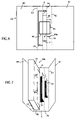
- FIG. 1 is a perspective view of a device including 3 L-shaped rib members for storing DVD cases in accordance with the invention.
- FIG. 2 is perspective view the same device, with rib members including a raised elevation at one extremity of each rib member.
- FIG. 3 is cross sectional side view of a device including 3 L-shaped rib members for storing DVD cases bonded together with an external flexible layer of plastic material.
- FIG. 4 is a perspective view of a single L-shaped rib member including external connecting means.
- FIG. 5 is a perspective view of a device including 3 L-shaped rib members removably inter-connected, for storing DVD cases in accordance with the invention.
- FIG. 6 is a top view of a sheet of plastic material die-cut in a special way in order to create the L-shaped ribs of the invention along with the necessary fold lines.
- FIG. 7 is a top perspective view of the die-cut sheet of plastic with the flaps raised to provide the required L-shaped ribs of the invention.
- This device is composed of a set of three pivotable L-shaped profiles or ribs 1 , 1 a and 1 b are shown, housing DVD cases 10 , 10 a and 10 b fixedly positioned within each profile by means of adhesive layer 4 , 4 a and 4 b .
- the adhesive layers can be placed by a transfer tape or other means, and include a protective tape 5 that the consumer removes prior to placing a DVD case.
- the device of the invention includes a plurality of pivotable and contiguous L-shaped ribs to accommodate between 3 and 6 DVD cases.
- L-shaped rib 1 b is pivotable to a maximum of 180 degrees along its longitudinal axis before resting against lower rib 1 .
- Ribs 1 , 1 a and 1 b are designed to pivot around an axes of rotation created by U-shaped hinges or grooves 6 and 6 a .
- the hinges can be covering the entire length of the L-shaped ribs or portions of it
- a rib member is so called for its ability to support and protect a DVD case and includes two perpendicular wall members or arms 2 and 3 for receiving case 10 , 2 a and 3 a for receiving case 10 a and 2 b and 3 b for receiving case 10 b , capable of fixedly housing the corner of a DVD case not including the case front cover panel 12 , 12 a and 12 b .
- Front cover panel 12 of DVD case 10 a is pivotable along hinge 14 to allow removing or returning compact disk 16 .
- adhesive layers 4 , 4 a and 4 b are shown to be placed on arm members 3 , 3 a and 3 b supporting the back side of the DVD cases 15 , 15 a and 15 b , they can also be placed on the spine side of the case 13 .
- FIG. 2 also shows anchor members 7 , 7 a and 7 b providing an anchor for DVD cases before placing them over the adhesive material in order to insure that all cases are lined up evenly, at least on the ground side of the device.
- the anchors can take several geometrical shapes and can even interlock or stack-up with each other in order to prevent thinner DVD cases from collapsing over each other.
- the device of the invention is placed on a flat surface for selecting, returning or simply browsing through DVD case covers.
- the device of the invention is typically placed on any standard shelf unit.
- FIG. 3 shows another embodiment of the invention with contiguous L-shaped ribs pivotably connected by an external flexible tape member 30 fixedly glued or otherwise bonded to outer side of arm members 3 , 3 a and 3 b .
- Rib 1 a is shown to include adhesive tape 30 a connected to one half of arm member 3 a , while the other half of tape 30 a is still protected by disposable tape 31 a , which must be removed or pealed by the consumer before adding another rib member.
- Flexible tape 30 creates a natural pivotable hinge member 6 at the intersection of two rib members.
- FIG. 4 and FIG. 5 represent a single and a plurality of removably attachable L-shaped ribs along a pivot axis defined by pivot parts and fastening means 20 and 21 .
- Several means of pivotable interlocking arrangements are known in the art.
- the outer corner of a rib member is shown to include a U-shaped channel or groove 20 , releasably adapted to receive protrusion member 21 for a snap fit connection.
- Removing or adding individual ribs with attached DVD cases may be nessary to reorganize a storage device, or to expand it. This would eliminate the need to tear-off a DVD case from its rib member and risk damaging it.
- the storage device of the invention in FIG. 6 and FIG. 7 is formed by folding a unitary sheet 50 of die-cut, rigid plastic material such as polypropylene, with a plurality of cut through U-shaped flaps 2 , 2 a and 2 b with their respective fold lines 44 , 44 a and 44 b allowing the flaps to manually pivot 90 degrees upwardly and be used as back side support for a DVD case 10 , 10 a and 10 b .
- fold lines 6 and 6 a represent the axis of rotation of each individual rib member with its corresponding DVD cases.
- Members 40 and 41 are pivotable along fold lines 42 and 43 , and represent the front and back covers of the device in the invention.
- the covers can also include retaining means such as an elastic cord or snap-on buttons.
Landscapes
- Packaging For Recording Disks (AREA)
- Packaging Of Annular Or Rod-Shaped Articles, Wearing Apparel, Cassettes, Or The Like (AREA)
Abstract
A device for storing and displaying a plurality of DVD cases and the like comprising a plurality of parallel rigid L-shaped profiles pivotably connected, characterized in that the convex side of each L-shaped profile includes at least one adhesive layer to fixedly attach at least one DVD case by the spine side or by its adjacent back side area, hence allowing the front covers of the case to pivot freely.
Description
The invention relates to media storage devices and methods for holding a collection of individual media units in general, and DVD cases in particular.
Various display racks and storage devices are well known in the art. They range from simple book shelves to stackable racks to carousels
While various cases have been developed for storing groups of CD's in order to reduce space and increase the organization, the DVD market does not enjoy the same trend. Related prior art on the construction of a CD case can be found in U.S. Pat. No. 4,874,085. DVD cases are generally much larger than CD cases and designed intentionally to provide maximum information on its content than its CD counterpart. With DVD's now the most popular medium for recorded movies, people are therefore looking for permanent ways to organize their collections in order to reduce the time consuming and often frustrating task to locate a particular movie.
While the majority of storage devices are designed to handle single DVD cases with no logical labeling methods, the consumer has no way of permanently arranging their library of DVD's into distinct collections or groups of DVD's featuring selected topics, actors, etc . . . , without the risk of others returning the DVD's into the wrong slot, constantly taking the sequence out of order. Such organization is becoming necessary, as large numbers of DVDs are owned by single families. While a similar situation happened with music CDs, cases for DVDs remain larger than CDs, with a larger spine area, which makes them more suitable for the present invention.
The purpose of the invention is to present an improved device for storing and organizing a group of DVD cases in a permanent order, and displaying them in a way similar to pages on a book. This device is to be used mostly by the consumer to organize existing collections of DVD's or alike.
DVD cases are generally injection molded or thermoformed from a rigid plastic material in a single case comprising three distinct parts; a base part for holding the compact disk on one side and the content description on the outer side; a folding cover panel showing the highlights of the DVD; and a flat spine containing the title of the DVD. The spine side of the case is perpendicularly and pivotably hinged to the front cover panel of the case while fixedly connected to the back side section of the case. The width of the spine and the adjacent area on the back side of the DVD case are joined at a 90 degrees angle and are the subject of the present invention.
The device of the invention includes a plurality of ridgid and pivotable L-shaped rib members or profiles, each comprising two flat arm or wall members at substantially right angles from each other, and including an adhesive layer placed in the inside of at least one of the arm members to fixedly attach the DVD case. The spine of the DVD case is placed directly on one arm of the rib member while the adjacent back side of the case is automatically lined-up against the other arm member. The consumer is required to first remove the protective layer of the double sided adhesive or the adhesive transfer tape in order to lodge the DVD into the right angle corner of the L-shaped rib.
Because the adhesive substance may blur the clarity of the title text displayed in the spine area of the DVD case, it may instead be placed on the opposing arm supporting the base cover. Sometimes, however, having one layer in each arm member of the rib may be required. The front cover of the DVD case remains unobstructed and free to pivot from its closed position to an open position for accessing the enclosed compact disk. The rib member, on the other hand remains hugging constantly the spine and back side corner of the DVD case.
In a first embodiment, the L-shaped rib members are parallel in orientation and connected contiguously with an integral U-shaped hinge or channel bridging the outer corner of one L-shaped rib to the extremity of one arm member of the next rib member. The U-shaped hinge allows two parallel, contiguous and rigid rib members to pivot to a maximum of 180 degrees from their original position. Another object of the invention is to provide each individual L-shaped rib member with an interlocking hinge mechanism in order to selectively connect it to the next rib member and to the previous one.
A further object of the invention is the connect a plurality of L-shaped profile members by bonding them together with a flexible sheet of transparent plastic or tape, over the outer side of each of the adjacent arm members supporting the spine sides of the DVD cases, providing in addition an integral hinge member along the intersection of the two contiguous rib members.
A still further object of the invention is to achieve the L-shaped construction for fixing a multitude of DVD cases by simply die-cutting a flat sheet of plastic material.
Other objects, advantages, and unique features of the invention will become more apparent from the following detailed description when taken in conjunction with the accompanying drawings.
With Reference to FIGS. 1 and 2 , the general configuration of the storage and display device of the invention can be appreciated. This device is composed of a set of three pivotable L-shaped profiles or ribs 1, 1 a and 1 b are shown, housing DVD cases 10, 10 a and 10 b fixedly positioned within each profile by means of adhesive layer 4, 4 a and 4 b.The adhesive layers can be placed by a transfer tape or other means, and include a protective tape 5 that the consumer removes prior to placing a DVD case. For practical reasons the device of the invention includes a plurality of pivotable and contiguous L-shaped ribs to accommodate between 3 and 6 DVD cases. L-shaped rib 1 b is pivotable to a maximum of 180 degrees along its longitudinal axis before resting against lower rib 1.
While adhesive layers 4, 4 a and 4 b are shown to be placed on arm members 3, 3 a and 3 b supporting the back side of the DVD cases 15, 15 a and 15 b, they can also be placed on the spine side of the case 13.
As shown in FIGS. 1 and 2 , the device of the invention is placed on a flat surface for selecting, returning or simply browsing through DVD case covers. For storage or display however, the device of the invention is typically placed on any standard shelf unit.
Removing or adding individual ribs with attached DVD cases may be nessary to reorganize a storage device, or to expand it. This would eliminate the need to tear-off a DVD case from its rib member and risk damaging it.
The storage device of the invention in FIG. 6 and FIG. 7 is formed by folding a unitary sheet 50 of die-cut, rigid plastic material such as polypropylene, with a plurality of cut through U-shaped flaps 2, 2 a and 2 b with their respective fold lines 44, 44 a and 44 b allowing the flaps to manually pivot 90 degrees upwardly and be used as back side support for a DVD case 10, 10 a and 10 b.
51 represents the empty holes left when flap members 2, 2 a and 2 b have been pushed through. While the combination of flap members 2 and 3, 2 a and 3 a, 2 b and 3 b, make-up the L-shaped ribs required by the invention, fold lines 6 and 6 a represent the axis of rotation of each individual rib member with its corresponding DVD cases. Members 40 and 41 are pivotable along fold lines 42 and 43, and represent the front and back covers of the device in the invention. The covers can also include retaining means such as an elastic cord or snap-on buttons.
Claims (7)
1. A media device for storing and displaying a DVD case having a spine, said DVD case, including a top cover panel for getting access to an inside of the case, pivotably hinged to a side of the spine of the DVD case for listing the title of the DVD, and a base member for holding at least one disk and providing the back cover for the DVD case, comprising:
at least a single substantially L-shaped rib member, said rib member made of plastic material and includes of two adjacent and perpendicularly arm members being pivotable on the spine whereby one arm member is able to receive the entire width of the spine, while the other arm member is able to receive at least the adjacent area to the spine located in a back side member of the case;
and hinge means for connecting a corner side of one L-shaped rib member to an outer extremity of one arm member of an adjacent L-shaped rib member having the same orientation and pivotable along the same longitudinal axis,
wherein the hinge means are in the form of a fold line engraved into a plastic sheet connecting at least in part two adjacent L-shaped ribs.
2. The storage device of claim 1 wherein the hinge means are in the form of a U-shaped channel connecting at least in part two adjacent L-shaped ribs.
3. The storage device of claim 1 wherein the hinge means are in the form of a grove on a flat surface connecting at least in part two adjacent L-shaped ribs.
4. A media device for storing and displaying a DVD case having a spine, said DVD case, including a top cover panel for getting access to an inside of the case, pivotably hinged to a side of the spine of the DVD case for listing the title of the DVD, and a base member for holding at least one disk and providing the back cover for the DVD case, comprising:
at least a single substantially L-shaped rib member, said rib member made of plastic material and includes of two adjacent and perpendicularly arm members being pivotable on the spine whereby one arm member is able to receive the entire width of the spine, while the other arm member is able to receive at least the adjacent area to the spine located in a back side member of the case;
and hinge means for connecting a corner side of one L-shaped rib member to an outer extremity of one arm member of an adjacent L-shaped rib member having the same orientation and pivotable along the same longitudinal axis,
wherein the L-shaped rib member includes at least one adhesive layer for fixedly attaching the spine member of at least one single case.
5. A media device for storing and displaying a DVD case having a spine, said DVD case, including a top cover panel for getting access to an inside of the case, pivotably hinged to a side of the spine of the DVD case for listing the title of the DVD, and a base member for holding at least one disk and providing the back cover for the DVD case, comprising:
at least a single substantially L-shaped rib member, said rib member made of plastic material and includes of two adjacent and perpendicularly arm members being pivotable on the spine whereby one arm member is able to receive the entire width of the spine, while the other arm member is able to receive at least the adjacent area to the spine located in a back side member of the case;
and hinge means for connecting a corner side of one L-shaped rib member to an outer extremity of one arm member of an adjacent L-shaped rib member having the same orientation and pivotable along the same longitudinal axis,
wherein the L-shaped rib member includes at least one adhesive layer for fixedly attaching the back side member of a single case.
6. A media device for storing and displaying a DVD case having a spine, said DVD case, including a top cover panel for getting access to an inside of the case, pivotably hinged to a side of the spine of the DVD case for listing the title of the DVD, and a base member for holding at least one disk and providing the back cover for the DVD case, comprising:
at least a single substantially L-shaped rib member, said rib member made of plastic material and includes of two adjacent and perpendicularly arm members being pivotable on the spine whereby one arm member is able to receive the entire width of the spine, while the other arm member is able to receive at least the adjacent area to the spine located in a back side member of the case;
and hinge means for connecting a corner side of one L-shaped rib member to an outer extremity of one arm member of an adjacent L-shaped rib member having the same orientation and pivotable along the same longitudinal axis,
wherein the L-shaped rib member including at least one adhesive layer for fixedly attaching a single case and an external adhesive tape for connecting a contiguous L-shaped rib.
7. A media device for storing and displaying a DVD case having a spine, said DVD case, including a top cover panel for getting access to an inside of the case, pivotably hinged to a side of the spine of the DVD case for listing the title of the DVD, and a base member for holding at least one disk and providing the back cover for the DVD case, comprising:
at least a single substantially L-shaped rib member, said rib member made of plastic material and includes of two adjacent and perpendicularly arm members being pivotable on the spine whereby one arm member is able to receive the entire width of the spine, while the other arm member is able to receive at least the adjacent area to the spine located in a back side member of the case;
and hinge means for connecting a corner side of one L-shaped rib member to an outer extremity of one arm member of an adjacent L-shaped rib member having the same orientation and pivotable along the same longitudinal axis,
wherein the L-shaped rib member includes a self adhesive hook and loop along the inside of at least one arm member for removably attaching a single DVD case.
Priority Applications (1)
| Application Number | Priority Date | Filing Date | Title |
|---|---|---|---|
| US10/644,985 US6971512B2 (en) | 2003-08-21 | 2003-08-21 | Storage device for DVD cases |
Applications Claiming Priority (1)
| Application Number | Priority Date | Filing Date | Title |
|---|---|---|---|
| US10/644,985 US6971512B2 (en) | 2003-08-21 | 2003-08-21 | Storage device for DVD cases |
Publications (2)
| Publication Number | Publication Date |
|---|---|
| US20050040058A1 US20050040058A1 (en) | 2005-02-24 |
| US6971512B2 true US6971512B2 (en) | 2005-12-06 |
Family
ID=34194200
Family Applications (1)
| Application Number | Title | Priority Date | Filing Date |
|---|---|---|---|
| US10/644,985 Expired - Fee Related US6971512B2 (en) | 2003-08-21 | 2003-08-21 | Storage device for DVD cases |
Country Status (1)
| Country | Link |
|---|---|
| US (1) | US6971512B2 (en) |
Cited By (2)
| Publication number | Priority date | Publication date | Assignee | Title |
|---|---|---|---|---|
| US20070193898A1 (en) * | 2006-02-21 | 2007-08-23 | Wen-Long Hu | Optical disc accommodating case |
| US20080053849A1 (en) * | 2006-09-05 | 2008-03-06 | Ara Alan Sarkis Sabounjian | Binder |
Families Citing this family (1)
| Publication number | Priority date | Publication date | Assignee | Title |
|---|---|---|---|---|
| US20070143191A1 (en) * | 2005-12-21 | 2007-06-21 | Sterling Publishing, Co., Inc. | Multimedia book and method |
Citations (5)
| Publication number | Priority date | Publication date | Assignee | Title |
|---|---|---|---|---|
| US1995273A (en) * | 1933-04-24 | 1935-03-19 | T A Miller | Chain link |
| US5040687A (en) * | 1990-06-26 | 1991-08-20 | Whittington Jeffrey L | Wall-mounted compact disc display |
| US5518112A (en) * | 1993-10-28 | 1996-05-21 | Hatakeyama Seisakusho Co., Ltd. | Software disk holder and assembly of disk cases therewith |
| US5964356A (en) * | 1997-04-11 | 1999-10-12 | Gareau; David | Modular storage rack for compact discs and the like data media |
| US6520347B2 (en) * | 1999-01-29 | 2003-02-18 | Sharper Image Corporation | Rack for compact discs |
-
2003
- 2003-08-21 US US10/644,985 patent/US6971512B2/en not_active Expired - Fee Related
Patent Citations (5)
| Publication number | Priority date | Publication date | Assignee | Title |
|---|---|---|---|---|
| US1995273A (en) * | 1933-04-24 | 1935-03-19 | T A Miller | Chain link |
| US5040687A (en) * | 1990-06-26 | 1991-08-20 | Whittington Jeffrey L | Wall-mounted compact disc display |
| US5518112A (en) * | 1993-10-28 | 1996-05-21 | Hatakeyama Seisakusho Co., Ltd. | Software disk holder and assembly of disk cases therewith |
| US5964356A (en) * | 1997-04-11 | 1999-10-12 | Gareau; David | Modular storage rack for compact discs and the like data media |
| US6520347B2 (en) * | 1999-01-29 | 2003-02-18 | Sharper Image Corporation | Rack for compact discs |
Cited By (2)
| Publication number | Priority date | Publication date | Assignee | Title |
|---|---|---|---|---|
| US20070193898A1 (en) * | 2006-02-21 | 2007-08-23 | Wen-Long Hu | Optical disc accommodating case |
| US20080053849A1 (en) * | 2006-09-05 | 2008-03-06 | Ara Alan Sarkis Sabounjian | Binder |
Also Published As
| Publication number | Publication date |
|---|---|
| US20050040058A1 (en) | 2005-02-24 |
Similar Documents
| Publication | Publication Date | Title |
|---|---|---|
| JP3263078B2 (en) | Wallet type compact disk storage unit | |
| US5513749A (en) | Storage case for multiple compact discs | |
| US5188228A (en) | Compact disk holder | |
| JP3215920B2 (en) | Separable module disk and flat object storage device | |
| US6626290B2 (en) | Storage container for recorded media | |
| US20100320104A1 (en) | Package with Security Features | |
| US7066325B2 (en) | Storage container for recorded media | |
| US8011503B2 (en) | Modular optical disc media storage system | |
| US5462177A (en) | Compact disc storage and display rack | |
| US6659272B2 (en) | System for storing and transporting discs and accessory materials | |
| US7191899B2 (en) | Disc cartridge storage case having presentation stand | |
| US6119381A (en) | Disc storage and display device | |
| US20100126890A1 (en) | Storage container for multiple data storage media | |
| US5950821A (en) | Compact disk storage case | |
| US6971512B2 (en) | Storage device for DVD cases | |
| US20050241970A1 (en) | Media disc storage device | |
| US6213312B1 (en) | Compact disk storage and filing systems | |
| US5690399A (en) | Compact disk stroage cabinet | |
| US5088674A (en) | Bracket for wall mounting a compact disk case | |
| US6000537A (en) | Housing with readable side walls for a disc-shaped information carrier | |
| US20040245131A1 (en) | Accordion-like compact disc carrying system | |
| AU707542B2 (en) | A wallet style compact disc storage unit | |
| KR200186910Y1 (en) | Apparatus for containing plural storage media | |
| JPH0754150Y2 (en) | Sliding CD case | |
| US20030221979A1 (en) | Compression disc holder |
Legal Events
| Date | Code | Title | Description |
|---|---|---|---|
| REMI | Maintenance fee reminder mailed | ||
| LAPS | Lapse for failure to pay maintenance fees | ||
| STCH | Information on status: patent discontinuation |
Free format text: PATENT EXPIRED DUE TO NONPAYMENT OF MAINTENANCE FEES UNDER 37 CFR 1.362 |
|
| FP | Lapsed due to failure to pay maintenance fee |
Effective date: 20091206 |