US6970391B2 - Semiconductor device incorporating internal power supply for compensating for deviation in operating condition and fabrication process conditions - Google Patents
Semiconductor device incorporating internal power supply for compensating for deviation in operating condition and fabrication process conditions Download PDFInfo
- Publication number
- US6970391B2 US6970391B2 US10/441,207 US44120703A US6970391B2 US 6970391 B2 US6970391 B2 US 6970391B2 US 44120703 A US44120703 A US 44120703A US 6970391 B2 US6970391 B2 US 6970391B2
- Authority
- US
- United States
- Prior art keywords
- voltage
- circuit
- current
- control
- mos transistor
- Prior art date
- Legal status (The legal status is an assumption and is not a legal conclusion. Google has not performed a legal analysis and makes no representation as to the accuracy of the status listed.)
- Expired - Fee Related
Links
Images


Classifications
-
- G—PHYSICS
- G11—INFORMATION STORAGE
- G11C—STATIC STORES
- G11C7/00—Arrangements for writing information into, or reading information out from, a digital store
- G11C7/12—Bit line control circuits, e.g. drivers, boosters, pull-up circuits, pull-down circuits, precharging circuits, equalising circuits, for bit lines
-
- G—PHYSICS
- G11—INFORMATION STORAGE
- G11C—STATIC STORES
- G11C11/00—Digital stores characterised by the use of particular electric or magnetic storage elements; Storage elements therefor
- G11C11/21—Digital stores characterised by the use of particular electric or magnetic storage elements; Storage elements therefor using electric elements
- G11C11/34—Digital stores characterised by the use of particular electric or magnetic storage elements; Storage elements therefor using electric elements using semiconductor devices
- G11C11/40—Digital stores characterised by the use of particular electric or magnetic storage elements; Storage elements therefor using electric elements using semiconductor devices using transistors
- G11C11/401—Digital stores characterised by the use of particular electric or magnetic storage elements; Storage elements therefor using electric elements using semiconductor devices using transistors forming cells needing refreshing or charge regeneration, i.e. dynamic cells
- G11C11/4063—Auxiliary circuits, e.g. for addressing, decoding, driving, writing, sensing or timing
- G11C11/407—Auxiliary circuits, e.g. for addressing, decoding, driving, writing, sensing or timing for memory cells of the field-effect type
- G11C11/409—Read-write [R-W] circuits
- G11C11/4094—Bit-line management or control circuits
-
- G—PHYSICS
- G11—INFORMATION STORAGE
- G11C—STATIC STORES
- G11C11/00—Digital stores characterised by the use of particular electric or magnetic storage elements; Storage elements therefor
- G11C11/21—Digital stores characterised by the use of particular electric or magnetic storage elements; Storage elements therefor using electric elements
- G11C11/34—Digital stores characterised by the use of particular electric or magnetic storage elements; Storage elements therefor using electric elements using semiconductor devices
- G11C11/40—Digital stores characterised by the use of particular electric or magnetic storage elements; Storage elements therefor using electric elements using semiconductor devices using transistors
- G11C11/41—Digital stores characterised by the use of particular electric or magnetic storage elements; Storage elements therefor using electric elements using semiconductor devices using transistors forming static cells with positive feedback, i.e. cells not needing refreshing or charge regeneration, e.g. bistable multivibrator or Schmitt trigger
- G11C11/413—Auxiliary circuits, e.g. for addressing, decoding, driving, writing, sensing, timing or power reduction
-
- G—PHYSICS
- G11—INFORMATION STORAGE
- G11C—STATIC STORES
- G11C5/00—Details of stores covered by group G11C11/00
- G11C5/14—Power supply arrangements, e.g. power down, chip selection or deselection, layout of wirings or power grids, or multiple supply levels
-
- G—PHYSICS
- G11—INFORMATION STORAGE
- G11C—STATIC STORES
- G11C5/00—Details of stores covered by group G11C11/00
- G11C5/14—Power supply arrangements, e.g. power down, chip selection or deselection, layout of wirings or power grids, or multiple supply levels
- G11C5/147—Voltage reference generators, voltage or current regulators; Internally lowered supply levels; Compensation for voltage drops
-
- G—PHYSICS
- G11—INFORMATION STORAGE
- G11C—STATIC STORES
- G11C8/00—Arrangements for selecting an address in a digital store
- G11C8/10—Decoders
-
- H—ELECTRICITY
- H03—ELECTRONIC CIRCUITRY
- H03K—PULSE TECHNIQUE
- H03K17/00—Electronic switching or gating, i.e. not by contact-making and –breaking
- H03K17/51—Electronic switching or gating, i.e. not by contact-making and –breaking characterised by the components used
- H03K17/56—Electronic switching or gating, i.e. not by contact-making and –breaking characterised by the components used by the use, as active elements, of semiconductor devices
- H03K17/687—Electronic switching or gating, i.e. not by contact-making and –breaking characterised by the components used by the use, as active elements, of semiconductor devices the devices being field-effect transistors
- H03K17/693—Switching arrangements with several input- or output-terminals, e.g. multiplexers, distributors
-
- H—ELECTRICITY
- H03—ELECTRONIC CIRCUITRY
- H03K—PULSE TECHNIQUE
- H03K19/00—Logic circuits, i.e. having at least two inputs acting on one output; Inverting circuits
- H03K19/003—Modifications for increasing the reliability for protection
- H03K19/00369—Modifications for compensating variations of temperature, supply voltage or other physical parameters
- H03K19/00376—Modifications for compensating variations of temperature, supply voltage or other physical parameters in bipolar transistor circuits
-
- H—ELECTRICITY
- H03—ELECTRONIC CIRCUITRY
- H03K—PULSE TECHNIQUE
- H03K19/00—Logic circuits, i.e. having at least two inputs acting on one output; Inverting circuits
- H03K19/003—Modifications for increasing the reliability for protection
- H03K19/00369—Modifications for compensating variations of temperature, supply voltage or other physical parameters
- H03K19/00384—Modifications for compensating variations of temperature, supply voltage or other physical parameters in field effect transistor circuits
-
- H—ELECTRICITY
- H03—ELECTRONIC CIRCUITRY
- H03K—PULSE TECHNIQUE
- H03K19/00—Logic circuits, i.e. having at least two inputs acting on one output; Inverting circuits
- H03K19/01—Modifications for accelerating switching
- H03K19/017—Modifications for accelerating switching in field-effect transistor circuits
- H03K19/01707—Modifications for accelerating switching in field-effect transistor circuits in asynchronous circuits
-
- H—ELECTRICITY
- H03—ELECTRONIC CIRCUITRY
- H03K—PULSE TECHNIQUE
- H03K19/00—Logic circuits, i.e. having at least two inputs acting on one output; Inverting circuits
- H03K19/0175—Coupling arrangements; Interface arrangements
- H03K19/017509—Interface arrangements
- H03K19/017518—Interface arrangements using a combination of bipolar and field effect transistors [BIFET]
-
- H—ELECTRICITY
- H03—ELECTRONIC CIRCUITRY
- H03K—PULSE TECHNIQUE
- H03K19/00—Logic circuits, i.e. having at least two inputs acting on one output; Inverting circuits
- H03K19/02—Logic circuits, i.e. having at least two inputs acting on one output; Inverting circuits using specified components
- H03K19/08—Logic circuits, i.e. having at least two inputs acting on one output; Inverting circuits using specified components using semiconductor devices
- H03K19/094—Logic circuits, i.e. having at least two inputs acting on one output; Inverting circuits using specified components using semiconductor devices using field-effect transistors
- H03K19/0944—Logic circuits, i.e. having at least two inputs acting on one output; Inverting circuits using specified components using semiconductor devices using field-effect transistors using MOSFET or insulated gate field-effect transistors, i.e. IGFET
- H03K19/09448—Logic circuits, i.e. having at least two inputs acting on one output; Inverting circuits using specified components using semiconductor devices using field-effect transistors using MOSFET or insulated gate field-effect transistors, i.e. IGFET in combination with bipolar transistors [BIMOS]
-
- H—ELECTRICITY
- H03—ELECTRONIC CIRCUITRY
- H03K—PULSE TECHNIQUE
- H03K5/00—Manipulating of pulses not covered by one of the other main groups of this subclass
- H03K5/01—Shaping pulses
- H03K5/08—Shaping pulses by limiting; by thresholding; by slicing, i.e. combined limiting and thresholding
-
- H—ELECTRICITY
- H03—ELECTRONIC CIRCUITRY
- H03K—PULSE TECHNIQUE
- H03K2217/00—Indexing scheme related to electronic switching or gating, i.e. not by contact-making or -breaking covered by H03K17/00
- H03K2217/0036—Means reducing energy consumption
Definitions
- the present invention relates generally to an improvement of performance of a semiconductor device and more particularly to a semiconductor device of high bit density realized in a structure suited for achieving high stability and enhanced reliability.
- the technique for realizing the semiconductor devices in the form of integrated circuits having high bit density has made remarkable progress in recent years.
- a MOS dynamic random access memory hereinafter referred to as a DRAM in abbreviation.
- the MOS DRAM of 1 Mbits is manufactured on a mass production basis.
- a test chip of a 4-Mbit DRAM has already been reported.
- a 16-Mbit-DRAM is undergoing development for practical applications.
- the size of the devices or elements constituting the semiconductor device as well as the size of wires must be made very small or fine in the range on the order of 0.5 ⁇ m to 1 ⁇ m.
- the gate length and the threshold voltages which mainly determine the characteristics of the MOS transistors constituting the MOS DRAM will vary significantly in dependence on fluctuation in the device size and impurity concentration.
- the access time of the DRAM will vary in the range from first to third order of magnitude. Further, deviations due to the fabrication process condition exert significant influence to the reliability of the device.
- degradation in the dielectric breakdown strength (dioxide breakdown strength) as well as degradation in the characteristics (due to hot carriers) occur as the result of implementation of the elements in small or minute size. Further, such characteristics concerning reliability of the device depend by and large on the dispersion in the implemented size.
- the operation voltage and/or operation current of the circuits and/or elements (devices) incorporated in the semiconductor device is controlled in accordance with the electrical characteristics whereby a semiconductor device of high stability and enhanced reliability can be realized.
- FIGS. 1 to 6 are schematic diagrams for illustrating the basic principle underlying the present invention.
- FIGS. 7 to 52 are schematic circuit diagrams showing exemplary embodiments of the invention.
- FIGS. 53 to 70 are schematic circuit diagrams showing exemplary embodiments of the invention applied to DRAM (dynamic random access memory) and SRAM (static random access memory).
- FIG. 1 is a schematic diagram for illustrating the basic principle underlying an embodiment of the present invention.
- reference numeral 1 denotes a semiconductor chip
- 2 denotes an internal circuit inherent to a semiconductor device
- a numeral 3 denotes a control circuit implemented according to the invention for generating control signals or controlled internal voltages in accordance a deviation in the condition in the fabrication process as well as the operating condition in which the semiconductor device is used.
- the control signal or internal voltage as generated is utilized for controlling operation of the internal circuit 2 by way of a control bus or line 5 .
- a single line 5 is shown, it will be readily understood that a number of signal lines may be prepared in the form of a bus in conformance with the configuration of the internal circuit 2 .
- the characteristics of the internal circuit 2 can be maintained in predetermined constant relationship in conformance with the fabrication process condition and the operating condition, whereby a semiconductor device enjoying high stability and improved reliability can be realized.
- FIG. 2 shows another exemplary embodiment of the present invention, which is so arranged that an operation characteristic of the internal circuit 2 such as, for example, operating speed, operating current or the like is detected by a detecting or sensing line 6 , whereby a corresponding control signal is generated.
- the semiconductor device shown in FIG. 2 differs from the one shown in FIG. 1 .
- FIG. 3 shows a further embodiment of the invention which differs from the one shown in FIG. 2 in that a detecting or monitor circuit 4 having characteristics similar to those of the internal circuit 2 is provided for detecting the operation characteristics thereof.
- the operation characteristics of the internal circuit can be detected indirectly in terms of the characteristics of the detecting or monitor circuit 4 even in the case where no proper circuitry is provided for detecting the operation characteristics of the circuit 2 , whereby the control can be so performed that the characteristics of the circuit 2 bear a predetermined relation.
- the detecting circuit 4 is also under the control of the control circuit 3 which serves to vary the characteristics of the detecting or monitor circuit 4 in a manner similar to the control of internal circuit 2 . It is conceivable to operate the detecting circuit 4 independent of the internal circuit 2 in accordance with the envisaged applications of the semiconductor device.
- FIG. 4 is a schematic diagram showing a version of the embodiment illustrated in FIG. 1 .
- a power supply source voltage is fed to the internal circuit 2 from the control circuit 3 by way of a power supply line 5 I.
- the instant embodiment of the invention is suited for the internal circuit implemented with small or fine elements. More specifically, by setting the potential on the power supply line 5 I at a value lower than the voltage which the elements constituting the internal circuit 2 can withstand, the semiconductor device constituted by the fine elements with high bit density can be operated while maintaining high stability and reliability. Further, since there arises no necessity to lower the external voltage, no burden is imposed on the user.
- the constituent elements In the case of the dynamic random access memory or DRAM, as the bit density is increased from 256 K bits to 1 M bits and hence to 4 M bits, the constituent elements have to be realized in more and more fine (minute) structure. In that case, lowering of the external voltage to cope with the lowering of the voltage withstanding capability of the constituent elements is undesirable, in order to assure the compatibility with the conventional devices. For this reason alone, the embodiment shown in FIG. 4 is advantageous. Although a plurality of control lines are shown in FIG. 4 , the operation characteristics of the internal circuit 2 can be stabilized by controlling the voltage by means of the control circuit.
- the voltage control may be carried out such that a variation in the internal voltage with reference to the external voltage V CC can be first compensated for, being followed by compensation of variations in the characteristics of the internal circuit 2 brought about by changes in the environmental conditions such as temperature and deviations in the fabrication process condition.
- the control circuit to which the external voltage V CC is applied directly is implemented by using the elements having the voltage withstanding capability or the breakdown strength exceeding the external voltage V CC .
- a voltage transformer circuit 3 A may be provided internally in the control circuit 3 , whereby a voltage lower than the level V CC is supplied through an output line 5 I to the internal circuit 2 as well as the circuitry 3 B of the low breakdown strength incorporated in the control circuit 3 , as is shown in FIG. 5 .
- the integration or bit density thereof can be further enhanced because the circuits inclusive of the control circuit can be realized with fine (minute) elements.
- control circuitry 3 B and the internal circuit 2 can be constituted by elements having identical characteristics, variation in the operation characteristics of the internal circuit 2 can be controlled very precisely on the basis of corresponding variations in the characteristics of the control circuitry 3 B, to a further advantage.
- FIGS. 1 to 5 it is assumed that a single control circuit is provided on one semiconductor chip. It should however be appreciated that the internal circuit 2 may be divided into several circuits each being provided with the respective control circuitry. To this end, the arrangements shown in FIGS. 1 to 5 may of course be combined appropriately on a case-by-case basis. With the arrangement that the internal circuit 2 is divided into several circuits for accomplishing the control of the operation characteristics thereof, such control can be achieved for realizing the optimum operation characteristics for the individual functions of the divided circuitries.
- FIG. 6 is a view illustrating, in graph form such control that the operating speed of the circuit is maintained constantly at values differing from one another. More specifically. a broken curve C 11 shown in this figure represents the operation speed of a conventional circuit incorporating no control circuitry. As will be seen from this curve, the operating speed varies significantly in dependence on the fabrication process condition and the operating conditions. In contrast, a circuit incorporating a number of control circuits according to the present invention can exhibit a constant high speed as indicated by a solid line curve B 11 . Of course, the circuit incorporating the control circuits and destined for low-speed operation can be maintained at a desired constant low speed, as indicated by a solid line curve A 12 .
- control can be equally realized that the operating speed of a circuit is increased as a function of increases in the temperature.
- control may be made such that a delay involved due to resistance of wiring conductors within a semiconductor device or wiring conductors interconnecting the semiconductor devices can be compensated for by the increased operating speed brought about by a temperature rise, to thereby maintain constant the speed of the semiconductor device or that of the whole system including the semiconductor devices.
- circuit characteristics can be protected against variation brought about in the fabrication process, which in turn means that yield of the products of satisfactory quality fabricated on the mass production basis can be improved. Further, since the circuit characteristics can be protected from variations as caused by changes in the operating condition, reliability of a system such as a computer which is realized by using the semiconductor devices according to the invention can be improved significantly.
- the timing margin can be set at a minimum value by virtue of the invariability of the characteristics. This in turn means that the operating speed of the semiconductor device can be correspondingly increased.
- DRAM dynamic random access memory
- the timing margin can be set to a minimum, whereby operating speed of the DRAM can be increased.
- TTL interface with the positive power source of V CC is assumed to be employed. It should however be appreciated that essentially the same effects can be attained even when an ECL interface is employed. The following description will be made on the assumption that the TTL interface is employed. However, this never means that the invention is restricted to the use of TTL interface. The present invention can be equally realized by using the ECL interface.
- FIG. 7A shows a detailed embodiment of the present invention which is designed for controlling a driver circuitry incorporated in a circuit 2 .
- the characteristics of the driver circuitry are controlled by varying the power supply voltage of the circuit.
- an element circuitry 2 ′ constituting a part of the circuit 2 is a CMOS inverter composed of a P-channel MOS transistor T P1 and an N-channel MOS transistor T N1 .
- the elementary circuitry 2 ′ may be another logic circuit such as a NAND and a NOR circuit. Further, it may be composed of bipolar transistors or a combination of a bipolar transistor and a MOS transistor, or a circuit constituted by a combination of these circuit elements.
- characteristics of the driver circuitry 2 ′ and hence that of the whole circuit 2 can be controlled by varying a voltage V CONT supplied from the control circuit 3 by way of the line 5 , whereby a semiconductor device enjoying a high stability and an improved reliability can be realized.
- Value of the control voltage V CONT is determined in dependence on the circuit configuration of the driver circuitries 2 ′ to be controlled, as is illustrated in FIG. 7B , by way of example.
- the control voltage V CONT may be varied in such a manner as illustrated in FIG. 7B in consideration of various factors.
- the CMOS invertor exhibits a delay time t d which bears a certain relation to a gate length L g , a threshold voltage V T , a thickness t ox of gate oxide film, a channel conductance ⁇ o , temperature T (absolute temperature) and a load capacity C L , which relation is approximately given by t d ⁇ C L ⁇ 1 ⁇ o ⁇ L g ⁇ 1 V CONT - V T ⁇ T 1.5 ( 1 )
- the delay time may be deviate more or less from the value determined by the above expression for various reasons. It is however safe to say that the relation given by the expression (1) is essentially valid for CMOS circuits in general.
- control voltage V CONT may be varied according to the relation given by the above expression (1) so that the delay time t d can be maintained constant.
- the delay time t d can be held substantially constant by increasing the value of the control voltage V CONT as the values of various variable factors (in the case of channel conductance ⁇ o , the reciprocal thereof) are increased.
- the operating speed can be maintained constant independent of variations in the fabrication process condition and the operating condition.
- response to the change in temperature is also taken into consideration. Consequently, performance of the circuit can be maintained substantially constant regardless of a variation in the ambient temperature as well as such variation in temperature as caused by differences in the amount of heat generated by the semiconductor device when in the standby state and when in the ordinary operating state, by way of example.
- control may be made from the expression (1) in accordance with ( V CONT ⁇ V T ) ⁇ T ⁇ n instead of ( V CONT ⁇ V T ) ⁇ T ⁇ 1.5 where n is selected greater than 1.5.
- the dioxide breakdown voltage (dielectric breakdown strength) becomes lowered as the gate length L g and thickness T ox of the gate oxide film are decreased.
- the control voltage V CONT may also be controlled in the manner illustrated in FIG. 7 B.
- the breakdown voltage (referred to as the hot carrier breakdown voltage) defining the upper limit of the operation voltage becomes lower as the gate length L g and the gate oxide film thickness T ox become smaller with the temperature T being lower.
- the voltage V CONT may be controlled in such a manner as illustrated in FIG. 7 B.
- the problem of degradation of the characteristics can be avoided, even when the hot carrier breakdown strength is lowered due to deviations ascribable to the fabrication process condition.
- the circuit characteristics can be maintained substantially constant through the control illustrated in FIG. 7 B.
- FIG. 7A is not restricted to the use of the CMOS inverter as the circuitry 2 ′, but various other circuits can be employed.
- a BiCMoS inverter shown in FIG. 8 may be employed.
- the output drive stage is constituted by the bipolar transistors.
- the collector of the bipolar transistor Q N3 is connected to the external supply voltage V CC .
- FIG. 9 shows a circuit arrangement in which the circuit shown in FIG. 7A is added with an output buffer circuit constituted by MOS transistors T N3 and T N4 .
- the operation speed and the output voltage of the circuit shown in FIG. 9 are controlled by the control voltage V CONT as with the case of the circuit shown in FIG. 7 A and is advantageous in that the driving capability of the control circuit 3 can be made smaller with the design being facilitated, as with the case of the circuit shown in FIG. 8 , because the drive current for a load capacity connected to the output is supplied from the external supply source V CC .
- FIG. 10 shows a circuit arrangement which differs from the one shown in FIG. 9 in that the N-channel MOS transistor T N3 in the latter circuit is replaced by the bipolar transistor Q N3 . Because of higher driving capability of the bipolar transistor Q N3 , the load can be driven at a higher speed, while the driving capability of the control circuit 3 ( FIG. 7A ) can be made smaller.
- the circuit characteristics can be controlled with the aid of the control voltage V CONT in the manner similar to that of the circuit shown in FIG. 7 A.
- FIG. 11A shows another embodiment of the invention for controlling the characteristics of the driving circuit.
- This figure shows only the circuit portion corresponding to the elementary circuitry 2 ′ shown in FIG. 7.
- a P-channel MOS transistor T P2 and an N-channel MOS transistor T N2 are inserted between the CMOS inverter constituted by P- and N-channel MOS transistors T P1 and T N1 and the external supply voltage V CC on one hand and the ground on the other hand, respectively, wherein the gate voltages V CONT and V′ CONT of the MOS transistors T P2 and T N2 are controlled to thereby control the operation current of the CMOS inverter so that the operation speed is controlled. More specifically, the operation speed is increased as the current is increased and vice versa.
- the delay time t d exhibits a tendency similar to that given by the expression (1) for various variable factors. Accordingly, the gate control voltage V CONT for the P-channel MOS transistor T P2 is varied from a large value to a small value while the gate control voltage V CONT , for the N-channel MOS transistor T N2 is varied from a small value to a large value, as the L g , V T , t ox , 1/ ⁇ o , T and C L are increased whereby the delay time t d can be maintained to be substantially constant.
- the operation current is supplied directly from the power supply source, wherein the control voltages V CONT and V CONT ′ can drive only the gates of the MOS transistors T P2 and T N2 , respectively.
- the driving capability of the control circuit 3 can be made smaller, which in turn means that the circuit design can be extremely facilitated.
- the control is performed with both channel MOS transistors T P2 and T N2 in the instant embodiment, it falls within the purview of the invention to provide only one of these MOS transistors in dependence on the envisaged application. In conjunction with the embodiment shown in FIG.
- a MOS inverter is employed. It should however be understood that the invention is not restricted to a MOS inverter but can equally be applied to various types of logic circuits such as a NAND circuit, NOR circuit or the like. To this end, the circuit portion denoted by DRIV may be replaced by a logic circuit imparted with the driving function.
- FIGS. 12A and 12B show further embodiments of the present invention in which the control principle described in reference to FIG. 11 is applied to a BiCMOS drive circuit which has a higher driving capability as compared with the CMOS circuit.
- the base current is fed to the base of a bipolar transistor from a MOS transistor to be amplified by the bipolar transistor for driving a load capacitance. Accordingly, the circuit operation speed can be controlled by controlling the base current with the circuit of such configuration as shown in FIG. 12 A.
- the bipolar transistor Q N3 is turned off with the transistor Q N4 being also turned on, whereupon discharge of the output is initiated.
- the base current of the bipolar transistor Q N4 is supplied from the output OUT.
- This base current can be controlled by the control voltage V CONT , which in turn means that the discharge rate of the output can be controlled by the control voltage V CONT ,.
- the operation speed of the BiCMOS drive circuit according to the instant embodiment can be controlled.
- the circuit portion DRIV shown in FIG. 11A may be simply replaced by a BiCMOS circuit shown in FIG. 12 B. In that case, the current is determined by the MOS transistors T P2 and T N2 shown in FIG. 11 A.
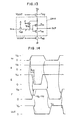
- FIG. 13 shows another embodiment of the invention which is applied to a level conversion circuit for deriving a large output amplitude from an input amplitude. Operation of the level conversion circuit will be described by reference to FIG. 14 .
- the input IN assumes a high level V A in the state where a high potential is applied to the gate E
- potential at a circuit point F assumes a value represented by (V A ⁇ V T ) by way of the N-channel MOS transistor T N3 .
- the amplitude V A of the input IN can be transformed to a large amplitude V H .
- the circuit can be operated at a desired constant speed.
- the circuit configuration shown in FIG. 13 can be effectively and advantageously utilized as a circuit for deriving a high output voltage from an input voltage, as exemplified by a word driver circuit for a dynamic memory.
- FIG. 15 shows another embodiment of the invention for controlling the operation speed of a driver circuit.
- the inverter is implemented so as to receive directly the output from the current control MOS transistor in the circuit shown in FIG. 11 A.
- the P-channel MOS transistors T P1 and T P3 are turned off with N-channel MOS transistors T N1 and T N3 being turned on.
- the control voltage V CONT is applied to the gate of the P-channel MOS transistor T P2 , while the potential at the gate of the N-channel MOS transistor T N2 assumes zero volt.
- the gate of the P-channel MOS transistor T P2 is supplied with the control voltage V CONT , while the gate potential of the N-channel MOS transistor T N2 becomes zero volt. Accordingly, the P-channel transistor T P2 is turned on with the N-channel transistor T N2 being turned off, whereby a current controlled to a desired value by the control voltage V CONT is obtained at the output to charge a load. In contrast, when the level of the input IN becomes low, the P-channel MOS transistor T P2 is turned off while the N-channel MOS transistor T N2 is turned on to thereby initiate the discharge operation, whereupon the output OUT assumes zero volt level.
- the rate of discharge can also be controlled.
- the embodiment shown in FIG. 15 is very suitable for high-speed operation because of the absence of a serial connection of two MOS transistors between the power supply source and the output OUT. Further, the control can be much facilitated when compared with the circuit shown in FIG. 11A where influences of a variation in the characteristics of two serially connected transistors has to be taken into consideration.
- FIG. 16 shows another exemplary embodiment of the invention in which the voltage transformer circuit mentioned above is provided on the chip.
- a reference symbol 5 I denotes a power supply line for supplying a voltage V I to the internal circuit 2 and a circuitry 3 B incorporated in the control circuit from the voltage transformer circuit 3 A.
- a reference symbol ICL denotes current control circuits for controlling the current to the individual circuits DRIV such as MOS transistors T P2 , T N2 shown in FIG. 11 A.
- FIG. 17 shows a further embodiment of the present invention adapted to control the operation speed of a CMOS inverter.
- voltages of substrates SBP 1 and SBP 2 of P-channel MOS transistor T P1 and N-channel MOS transistor T N1 are controlled to thereby control the threshold voltages of these transistors T P1 and T N1 for controlling ultimately the operation characteristics of the inverter.
- the instant embodiment is advantageously suited to compensate for variation in the characteristics brought about by a fluctuation of the threshold voltage.
- FIG. 17 is intended for application to the CMOS inverter, it should be noted that the instant embodiment can be equally applied to other circuits such as a BiCMOS inverter in which MOS transistors are employed. Besides, it is to be added that the control of the substrate voltages may be combined with the other control methods described hereinbefore.
- FIGS. 7 to 17 The foregoing description made by reference to FIGS. 7 to 17 is primarily directed to the methods of controlling the characteristics of the driver circuits such as inverters, non-inverters NAND circuits and others. It is however noted that a differential amplifier in the form of an integrated circuit for producing an output in dependence on a difference between input voltages is also used widely. The following description will be made of the embodiments of the invention applied to the differential amplifiers.
- FIG. 18 shows an embodiment of the invention in which the control method described hereinbefore with reference to FIG. 11A is applied to the control of operation speed of a differential amplifier constituted by MOS transistors.
- reference symbols IN 1 and IN 2 denote differential input terminals
- OUT 1 and OUT 2 denote differential output terminals.
- the operation speed varies in dependence on deviations in the fabrication process condition as well as variations in the operating condition in a manner similar to the case of the device shown in FIG. 11 A. Accordingly, by varying the control voltages V CONT and V CONT , in a similar manner as illustrated in FIG.
- the output voltage of this differential amplifier is determined by a product of the operation current and ON-resistances (i.e. resistance in the conducting state) of the load MOS transistors T PL and T PL ,. Accordingly, by controlling the control voltages V CONT and V CONT , so that the ratio between the ON-resistance of the MOS transistor T NC which determines the operation current and the ON-resistance of the load MOS transistors T PL and T PL , is constant, the operation speed can be controlled while holding constant the output voltage, i.e. the product of the operation current and the ON-resistances of the transistors T PL and T PL ,.
- FIG. 19 shows another embodiment of the invention which differs from that shown in FIG. 18 in that the MOS transistors T NA and T NA , shown in FIG. 18 are replaced by NPN-bipolar transistors Q NA and Q NA , respectively.
- the circuit configuration shown in FIG. 19 substantially the same effects as those of the circuit shown in FIG. 18 can be achieved. Moreover, the amplification factor can be increased.
- FIG. 20 shows a second version of the embodiment shown in FIG. 19 .
- the current control transistor T NC shown in FIG. 19 is replaced by an NPN-bipolar transistor Q NC and a resistor R C .
- the operation speed can be controlled as with the case of the embodiments shown in FIGS. 18 and 19 .
- the amplification factor can be increased because the operation current is made to be more constant.
- a desired voltage can be derived by providing the voltage limiter or transformer circuit 3 A on chip, as in the case of the embodiment shown in FIG. 5 .
- FIG. 21 illustrates a first embodiment of the control circuit 3 .
- a reference symbol T PR denotes a P-channel MOS transistor and CC denotes a constant current power source for supplying a constant current i .
- a gate voltage required for causing a constant current to flow through the P-channel MOS transistor T PR is constantly outputted regardless of deviation in the fabrication process condition, i.e. deviation in the gate length, threshold voltage, gate oxide film thickness and other factor as well as variation in the operating condition.
- this embodiment is advantageously suited for use as the control voltage (V CONT ) generating circuit to be used in combination with the circuits described hereinbefore by reference to FIGS. 11A , 12 and 13 , FIG. 15 and FIGS.
- the P-channel MOS transistor T PR shown in FIG. 21 is connected to the transistor T P2 shown in FIGS. 11A , 12 , and 13 , and FIG. 15 or the transistors T PL and T PL , shown in FIGS. 18 to 20 in the form of a current mirror connection well known in the art. Accordingly, by appropriately selecting the size of the transistor T P2 or T PL and T PL , relative to that of the transistor T PR , the operation current in the concerned circuits can be controlled to a given constant value.
- FIG. 22 shows another embodiment of the control circuit (3) which differs from the one shown in FIG. 21 in that an N-channel MOS transistor is employed.
- the control circuit shown in FIG. 22 is optimal for use as the control voltage (V CONT ,) generating circuit in combination with the circuits shown in FIGS. 11A , 12 , and 13 , FIG. 15 and FIGS. 18 and 19 , respectively.
- V CONT control voltage
- FIG. 23 shows another embodiment of the invention which corresponds to a combination of the circuits shown in FIGS. 21 and 22 .
- the control voltages VC ONT and V CONT for the circuits shown in FIGS. 11A , 12 and 13 , FIG. 15 and FIGS. 18 and 19 , respectively, can be generated simultaneously. Additionally, since these control voltages V CONT and V CONT , are generated on the basis of one and the same constant current power supply source, there can be obtained the control voltages (V CONT and V CONT ,) of extremely high stability and mutual match ability.
- FIG. 24 shows still another concrete example of the control circuit (3) which is realized by a serial connection of a P-channel MOS transistor T PR and an N-channel MOS transistor TNR for generating the control voltage V CONT .
- the value of the control voltage V CONT undergoes influence of deviations in the process conditions in fabrication of the P- and N-channel MOS transistors as well as variations in the operating conditions. Accordingly, this circuit can be advantageously used as the V CONT -generating circuit in the devices shown in FIGS. 7 to 10 , respectively.
- FIG. 25 shows another embodiment of the control circuit (3) according to the invention which differs from that shown in FIG. 24 in that an amplification circuit composed of an amplifier 7 and a feedback circuit having a feedback ratio ⁇ is additionally provided on the output side.
- V CONT V O ⁇ ( 3 )
- V CONT V O ⁇ ( 3 )
- FIG. 26 shows a concrete example of the constant current power source CC.
- the constant current power source C C1 is constituted by resistors R 1 to R 4 and NPN-bipolar transistors Q N1 and Q N2 .
- the base voltage B N1 of the bipolar transistor Q N1 assumes a constant value given by V BE (R 2 +R 3 )/R 3 , provided that the current amplification factor of the bipolar transistor is sufficiently large.
- VBE represents a forward voltage between emitter and base of the bipolar transistor.
- this embodiment is advantageously suited for use as the constant current power source in such circuit as shown in FIG. 21 .
- FIG. 27 shows another embodiment of the constant current power source which is realized by using PNP-bipolar transistors Q P1 and Q P2 . Operation of this constant current circuit is utterly same as that of the circuit shown in FIG. 26 with only a difference in the polarity of voltage and current. Because of the circuit configuration in which the current i flows out from the voltage source V CC , this circuit is very suitable for the constant current source in the circuit such as shown in FIG. 25 .
- FIG. 28 shows still another embodiment of the constant current source of the type in which the current flows out from a voltage supply source as in the case of the circuit shown in FIG. 27 .
- the constant current source shown in FIG. 28 is however realized by using NPN-bipolar transistors Q N1 and Q N2 .
- the operation current flowing through the resistors R 1 , R 2 and R 3 and the NPN-bipolar transistor Q N2 is added to the constant current.
- influence of the above-mentioned operation current may be neglected by setting the current amplification factor of the transistor Q N1 at a sufficiently large value.
- the constant current supply source of the type in which the current flows out from the voltage supply source V CC can be fabricated in a facilitated manner by using NPN-bipolar transistors of high performance.
- the constant current supply source shown in FIG. 29 can be used either in an arrangement in which the current flows into the current source circuit or in an arrangement in which the current flows out from the current source circuit.
- FIG. 29 shows an application of the above-mentioned constant current supply source to the circuit shown in FIG. 23 .
- the control voltages V CONT and V CONT simultaneously.
- FIG. 30 shows a further embodiment of a constant current supply source of the type in which the current flows out from the voltage supply source V CC and which is realized by a current mirror circuit constituted by a current source CC implemented such that the current flows to the ground as in the case of the constant current source shown in FIG. 26 and P-channel MOS transistors T PM and T PM ,.
- a current mirror circuit constituted by a current source CC implemented such that the current flows to the ground as in the case of the constant current source shown in FIG. 26 and P-channel MOS transistors T PM and T PM ,.
- a current having a same value as the output current i of the current source CC can be derived externally from the voltage supply source.
- the control voltage V CONT can be obtained.
- the output can be determined rather arbitrarily for the current value of the current source CC by selecting appropriately the ratio in size between the P-channel MOS transistors T PM and T PM ,.
- FIG. 31 shows a modification of the constant current supply source shown in FIG. 30 .
- the voltage generated through cooperation of the P-channel MOS transistor T PM and the current source CC is utilized as the control voltage V CONT .
- the control voltages V CONT and V CONT simultaneously, wherein the characteristics of both voltages can be controlled with an improved match ability, to further advantage.
- FIG. 32 shows another embodiment of the constant current supply source having a high stability and realized by using MOS transistors.
- T N61 to T N63 designate N-channel MOS transistors, respectively, wherein the MOS transistor T N61 has a negative threshold voltage while the transistor T N62 has a positive threshold voltage.
- the threshold voltage of the MOS transistor T N63 may be positive or negative.
- Symbols R 61 to R 63 designate resistors, and 7 denotes a differential amplifier.
- the gate voltage V I6 of the transistor T N62 has a value equal to a difference between the threshold voltages of the transistors T N61 and T N62 .
- the value of a difference between these threshold voltages is held substantially constant independent of the fabrication process condition and the operating condition.
- the constant current supply source according to the instant embodiment can be used as the current supply source CC in the circuit shown in FIG. 31 as well as other circuits to make possible the characteristic of high stability control.
- the circuit can be implemented even without resorting to the use of the bipolar transistors and thus is suited for the integrated circuit constituted by using MOS transistors.
- FIG. 33 shows a further embodiment of the constant current supply source advantageously suited to use with the circuits shown in FIGS. 21 to 25 and FIGS. 30 and 31 .
- a current generator known per se is made use of as the constant current supply source which can supply a current which is highly stabilized against fluctuations in the source voltage and the ambient temperature among others.
- reference symbols Q 51 to Q 56 designate bipolar transistors and R 51 to R 55 designate resistors, respectively. These elements cooperate to generate a constant current i having desired temperature characteristics. Further, reference symbol i 51 represents a current flowing through the resistor R 51 , i 52 represents a collector current of the bipolar transistor Q 52 and i 53 represents a collector current of the bipolar transistor Q 53 .
- i 51 represents a current flowing through the resistor R 51
- i 52 represents a collector current of the bipolar transistor Q 52
- i 53 represents a collector current of the bipolar transistor Q 53 .
- V I1 V BE ( Q 51 )+ I 52 ⁇ R 52 +V BE ( Q 52 ) ⁇ V BE ( Q 56 ) (6)
- V BE (Q 51 ), V BE (Q 52 ) and V BE (Q 56 ) represent base-emitter forward voltages, respectively.
- V I1 V BE ⁇ ( Q 51 ) + R 52 R 54 ⁇ k ⁇ ⁇ T q ⁇ l n ⁇ n + V BE ⁇ ( Q 52 ) - V BE ⁇ ( Q 56 ) ( 9 )
- V I1 V BE ⁇ ( Q 51 ) + R 52 R 54 ⁇ k ⁇ ⁇ T q ⁇ l n ⁇ n ( 10 )
- the base-emitter voltage of the bipolar transistor exhibits a negative temperature dependency.
- ⁇ V I1 / ⁇ T given by the expression (9) can be set at an arbitrary value.
- the circuit under consideration is generally referred to as a band-gap generator.
- the operation characteristics of the circuit can be controlled in an arbitrary manner by setting the temperature coefficient of the constant current supply source at zero or alternatively at a given positive or negative value.
- the internal voltage V I1 in the circuit according to the instant embodiment can be used as a constant voltage supply of high stability.
- the output terminal may be connected to the external voltage supply source V CC .
- the internal voltage V I1 can be utilized as the control voltage V CONT , for the circuit shown in FIG. 20 . In that case, it becomes possible to control the temperature characteristic of the differential amplifier.
- the circuit characteristic control method according to the present invention has been described in conjunction with several illustrative embodiments. Certainly, these embodiments can be easily realized. However, when fine (small) elements are used for the realization with a view to increasing the integration density (bit density), there may arise such situation in which difficulty is encountered in directly applying the external voltage V CC because of rather small dielectric (dioxide) breakdown strength of the fine elements. Besides, variations in the external voltage may make it difficult to obtain the desired characteristics. Under these circumstances, it is preferred to generate the stable internal voltage V I on chip and use that voltage V I in place of V CC , as with the case of the embodiments shown in FIGS. 4 , 5 and 16 .
- the external voltage V CC may be utilized.
- the burden imposed on the voltage supply source generating the internal voltage V I can be correspondingly reduced, whereby the internal voltage V I can be obtained to be stable.
- FIG. 34 shows an exemplary embodiment for controlling the operation speed of the circuit in which the internal voltage V I is utilized.
- the following description is based on the assumption that the CMOS invertor shown in FIG. 11A is controlled by the circuits shown in FIGS. 21 and 22 , respectively, it should be understood that the embodiment of the invention elucidated below can be applied to other various embodiments described hereinbefore.
- P-channel MOS transistors T P2 and T PR and N-channel MOS transistors T N2 and T NR constitute a current mirror circuit.
- the charge current of the driver circuit DRIV can be set at an arbitrary value.
- the discharge current can be set at an arbitrary value.
- source voltage of the P-channel MOS transistors T PR and T P2 and the voltage V I of the current supply source CC2 are held at a value lower than the voltage level which the small or fine elements can withstand, the latter can of course be used.
- the output amplitude is V I , the voltage which is an input to a succeeding stage can be controlled stably, whereby the stable operation of the succeeding stage can be assured.
- the control voltage (V CONT , V CONT ) generating circuits 31 and 32 can be used in common among a plurality of circuits. In that case, the operation speed of the individual circuits can be controlled as desired by setting the sizes of the associated MOS transistors T P2 and T N2 for every circuit separately.
- FIG. 35 shows a circuit configuration of the voltage transformer (limiter) circuit 35 according to an embodiment of the present invention.
- a reference character A denotes generally a voltage transformer circuit
- F denotes a constant voltage generating circuit
- G denotes an amplifier.
- the constant voltage generating circuit F is adapted to generate a constant voltage V I1 from the external supply voltage V CC .
- the amplifier G amplifies-the voltage V I1 to output a voltage V I of the value required by the internal circuit 2 or by a circuit portion 3 A of the control circuit 3 onto the control line 5 I. It should be mentioned that the voltage V I may be imparted with various characteristics through the constant voltage generating circuit F and the amplifier G.
- the output amplitude of the circuit such as the circuit shown in FIG. 34 can be made constant independent of the temperature, whereby the circuit operation of high stability can be realized.
- the output voltage V I1 of the constant voltage circuit can be amplified to a desired value through the amplifier G.
- the value or level of the voltage V I can be set without being limited to the value of the output voltage V I1 of the constant voltage circuit.
- FIG. 36 shows another embodiment of the voltage transformer circuit which differs from the circuit shown in FIG. 35 in that the amplifier GD and a feedback circuit H are provided.
- the feedback circuit H is so designed that when the voltage V I assumes a desired value, a voltage equal to the constant voltage V I1 is outputted to the output line I 2 .
- fluctuation in the output voltage V I is fed back through the feedback circuit H, whereby the value of the output voltage V I can be maintained constant with high accuracy even when the current supplied by way of the control line 5 I changes at high speed in the course of time lapse.
- FIG. 37 shows a circuit configuration of constant voltage generating circuit for use in the embodiments shown in FIGS. 35 and 36 .
- This constant voltage generating circuit corresponds substantially to the current supply circuit shown in FIG. 33 except that the collector of the bipolar transistor is connected to the external supply voltage V CC .
- the output voltage V I1 and the temperature dependency thereof are given by the aforementioned expressions (8) and (9), respectively.
- the temperature dependency can be established.
- the value of ⁇ VI1/ ⁇ T is so determined as to match with the temperature characteristics of the amplifier G serving as the differential amplifier GD and the feedback circuit H of the succeeding stage, whereby the temperature dependency of the output voltage V I of the voltage transformer circuit can be nullified.
- the voltage V I1 remains substantially constant independent of the external voltage V CC when the latter exceeds a value about twice as high as that of the base-emitter forward voltage of the bipolar transistor, i.e. about 1.8 volt. Accordingly, by applying the instant embodiment to the circuits shown in FIGS. 35 and 36 , the output voltage V I exhibiting neither the temperature dependency nor the external voltage dependency can be obtained in a facilitated and convenient manner.
- the constant voltage circuit F and other circuits are formed simultaneously in one and the same semiconductor substrate, same type of transistors, i.e. either the MOS transistors or the bipolar transistors should preferably be used in view of the simplification of the fabrication process and reduction in the manufacturing cost. For this reason, it may be desirable to use the MOS transistors in implementing the constant voltage circuit F rather than the bipolar transistors as in the case of the embodiment shown in FIG. 37 . In that case, the voltage V I6 , in a circuit corresponding to the one shown in FIG. 32 except that the drain of the MOS transistor T N63 is connected to the external supply voltage V CC , may be used.
- FIG. 38 shows a circuit configuration of the differential amplifier GD constituting a part of the circuit shown in FIG. 36 .
- the output voltage V I1 of the constant voltage circuit F is applied to the terminal I 1 while the output voltage V I2 of the feedback circuit is applied to the terminal I 2 .
- the terminals I 1 and I 2 correspond to the base electrodes of the bipolar transistors, respectively, gain can be increased while fluctuation in the voltage V I can be suppressed to a negligible level.
- the P-channel MOS transistors in the circuit shown in FIG. 38 may be replaced by resistors, as is shown in FIG. 39 . Since the resistor can be constituted by the base diffusion layer of the bipolar transistor, this resistor can be realized within an impurity layer for the collector of the bipolar transistor. Thus, the layout area of the circuit can be decreased.
- the current source for the differential amplifiers shown in FIGS. 38 and 39 there may be conceived various types of circuits. It is however possible to realize the current source circuit with a single MOS transistor, as is illustrated in FIGS. 40 and 41 . More specifically, the gates of the MOS transistors T I61 and T I71 are connected to the terminal I 1 . With this circuit arrangement, the current of the differential amplifier can be held constant independent of the external voltage V CC , since V I1 , assumes a constant value for V CC , as described hereinbefore. Further, when the characteristics of the differential amplifier need to be controlled stably, various controls may be performed with the aid of the circuits shown in FIGS. 18 to 20 .
- FIG. 42 shows a circuit configuration of the feedback circuit shown in FIG. 36 .
- V I2 R 82 R 81 + R 82 ⁇ V I ( 13 )
- V I2 R 82 R 81 + R 82 ⁇ V I ( 13 )
- FIG. 43 shows concretely a circuit configuration of the feedback circuit H shown in FIG. 36 .
- the control line 5 I is not directly connected to the resistor but connected to the base electrode of the bipolar transistor Q 91 Accordingly, owing to the current amplification by the bipolar transistor Q 21 , circuit operation of higher speed can be realized when compared with the circuit shown in FIG. 42 . Further, the load current of the differential amplifier GD can be decreased. In the case of the circuit shown in FIG.
- V I2 R 92 R 91 + R 92 ⁇ ⁇ V I - V BE ⁇ ( Q 91 ) ⁇ ( 15 )
- V I1 R 92 R 91 + R 92 ⁇ ⁇ V I0 - V BE ⁇ ( Q 91 ) ⁇ ( 16 )
- the output voltage can be maintained at a constant value lower than the external voltage V CC even when the latter is increased excessively, whereby the fine elements or devices can be protected against destruction, to a great advantage.
- V CC external voltage
- the integrated circuits usually undergo a so-called aging test after the final fabrication step, wherein a higher voltage than that used in the ordinary operation is intentionally applied to the individual transistors implemented within the integrated circuit for finding out at an earlier stage those transistors inherently susceptible to failure due to defect in the gate oxide film for thereby enhancing the reliability of the products.
- a higher voltage than that used in the ordinary operation is intentionally applied to the individual transistors implemented within the integrated circuit for finding out at an earlier stage those transistors inherently susceptible to failure due to defect in the gate oxide film for thereby enhancing the reliability of the products.
- a voltage which is slightly lower than the voltage at which a normal element or device would be destroyed has to be applied to the individual elements or device.
- the internally generated voltage V I is held at a constant value V I0 when the external power supply voltage lies within a range of V CI to V CE , while the internal voltage V I is increased as the external power supply voltage V CC is increased beyond the level V CE .
- the internal voltage V I can be increased. Accordingly, a voltage higher than the constant internal voltage level V I0 can be applied to the on-chip circuitries by increasing the external power supply voltage V CC beyond the level V EC in the aging test, which test thus can be carried out effectively.
- FIG. 45 shows a circuit arrangement for realizing the voltage characteristics illustrated in FIG. 44 .
- the constant voltage generating circuit F is similar to the circuit shown in FIG. 37 except for the differences mentioned below. Namely, a resistor R 111 is inserted between the collector of the bipolar transistor in the output stage J and the terminal D.
- the differential amplifier GD and the feedback circuit H are interconnected in the same manner as in the case of the circuit shown in FIG. 36 .
- the collector of the bipolar transistor Q 111 is connected to the base of the bipolar transistor Q 112
- the emitter of the latter is connected to the control line 5 I with the collector thereof being coupled to the external power supply voltage V CC .
- the output voltage V I remains constant at the value V I0 until the bipolar transistor Q 112 is turned on after the external power supply voltage V CC has reached the stable point V I0 of the output voltage V I , which is increased as the external voltage V CC increases after the bipolar transistor Q 112 has been turned on.
- V CE V I0 +V BE ( Q 112 )+ R 111 ⁇ i 11 (19)
- V CE V I0 + V BE ⁇ ( Q 112 ) + R 111 R 112 ⁇ V I1 ( 21 )
- the temperature dependency of the voltage V BE is about ⁇ 2 mV/° C. Accordingly, the temperature dependency of the voltage V CE as well as that of V I is extremely small when V CE >V CC .
- ⁇ 3 ⁇ 8.
- the values of ⁇ V CE / ⁇ T and ⁇ VE / ⁇ T when V CC >V CE are about ⁇ 1.25 mV/° C. and about +1.25 mV/° C., respectively. This means that even when the circuit shown in FIG. 43 is employed as the feedback circuit H, the temperature dependency of the voltage level V CE as well as that of V E when V CC >V CE is very small. Further by selecting the value of V CE about twice as large as the value of V I0 when the circuit shown in FIG. 43 is employed, the temperature dependency of V CE and that of V I when V CC >V CE can be simultaneously made approximately zero.
- ⁇ V BE ⁇ ( Q 91 ) ⁇ T ⁇ ⁇ V BE ⁇ ( Q 112 ) ⁇ T ( 35 ) then ⁇ V CE / ⁇ T ⁇ 0 from the expression (23a).
- the voltage characteristics illustrated in FIG. 44 can be realized without undergoing any appreciable influence of fluctuation in the temperature by using the circuit shown in FIG. 42 or the circuit shown in FIG. 43 as the feedback circuit H.
- the voltage V I exhibiting substantially no temperature dependency can be generated not only in the ordinary operation range of V CC ⁇ V CE but also in the aging test range of V CC >V CE , whereby the internal circuits can be operated stably.
- the bipolar transistor Q 112 is employed for raising the internal voltage V I when V CC ⁇ V CE .
- this transistor may be replaced by an N-channel MOS transistor, wherein the gate of that N-channel MOS transistor is connected to the terminal K while the drain thereof is connected to the external power supply V CC with the source of that transistor being connected to the terminal E. Since the terminal K is connected to the gate of the N-channel MOS transistor, there is required no current supply, whereby the design of the constant voltage generating circuit can be facilitated correspondingly.
- a buffer circuit for amplification of current may be provided in the voltage transformer circuit A, wherein the output line 5 I′ of the buffer circuit may be made use of as the control line for preventing fluctuation in the voltage.
- FIG. 46 shows an embodiment of the above-mentioned buffer circuit, wherein C 121 and C 122 designate capacitors for suppressing fluctuation in potential on the control line 5 I′.
- the voltages VI′ and VI are substantially equal to each other in the range given by
- FIG. 47 shows another embodiment of the buffer circuit which differs from the one shown in FIG. 46 in that the bipolar transistor is replaced by the MOS transistor.
- the voltage V I ′ is substantially equal to the internal voltage VI in the range given by V CC ⁇ V I +V TH (Q 132 ) (39) where V TH represents the threshold voltage of the MOS transistor.
- the threshold voltage of the MOS transistor can be easily controlled, it is possible according to this embodiment to stabilize the output voltage V I ′ starting from the state in which the external voltage V CC is still at a low level, by making the output voltage V I ′ equal to the internal voltage V I .
- the range of the external voltage V CC in which the internal voltage V I and the output voltage V I ′ become equal to each other is limited by the forward voltage in the base-emitter path of the bipolar transistor or by the threshold voltage of the MOS transistor. Accordingly, even when the circuit shown in FIG. 46 is designed such that the output voltage V I of the voltage transformer circuit becomes constant at 4 volts with the external voltage V CC being equal to or higher than 4 volts, by way of example, the output voltage V I ′ of the buffer circuit shown in FIG. 46 can not become constant at 4 volts unless the external voltage becomes equal to or higher than about 4.8 volts.
- the buffer circuit of such configuration as shown in FIG. 48 may be employed.
- the control line 5 I′ is connected to a drain electrode of a P-channel MOS transistor M 141 having a source electrode connected to the external power supply voltage V CC , while the gate G 141 of the MOS transistor is connected to the output of a differential amplifier Q so as to be controlled by the output voltage thereof.
- the input terminal of the differential amplifier Q is supplied with the output voltage V I of the voltage transformer (limiter) circuit A and the output voltage V I ′ of the buffer circuit under consideration.
- the capacitor C 141 serves for suppressing fluctuation in the output voltage V I ′.
- the output voltage V I ′ can be held at a value equal to the voltage V I by means of the differential amplifier mentioned above.
- the output voltage V I ′ can be made equal to the internal voltage V I independent of the external voltage V CC in the case of the embodiment shown in FIG. 48 , whereby a stable voltage can be derived over a wide range of the external voltage V CC .
- FIG. 49 shows a concrete example of the circuit configuration for the circuit shown in FIG. 48 .
- terminals P and ⁇ overscore (P) ⁇ are supplied with signals of opposite phases, respectively.
- the signal P is of high level with the signal ⁇ overscore (P) ⁇ being low level, essentially same effect can be obtained even when the level of these signals is reversed.
- the external voltage V CC is assumed to be 5 volts with the internal voltage V I being 4 volts, it goes without saying that other voltage values may also be used within the purview of the invention.
- the base-emitter voltage of the bipolar transistor is assumed to be 0.8 volt.
- the base potential V B153 of the bipolar transistor Q 153 is 1.6 volts.
- the potential V I ′ on the control line 5 I′ assumes the base potential V B154 of the bipolar transistor Q 154 , i.e. 1.6 volts.
- the collector current of the bipolar transistor Q 154 is decreased.
- the collector current of the bipolar transistor Q 153 is increased, which results in that the current flowing through a resistor R 151 is increased.
- the gate potential V GM141 of the MOS transistor T M141 is lowered, whereby the drain current of the MOS transistor T M141 is increased, as the result of which the voltage V I ′ is restored to 4 volts.
- the gate potential V GM141 becomes high, causing the MOS transistor T M141 to be turned off.
- the voltage V I ′ is lowered to restore 4 volts.
- the collector potential of the bipolar transistor Q 153 is prevented from being lowered below 2.6 volts because of a series connection of diodes D 153 to D 155 inserted between the collector of the transistor Q 153 and the external power supply V CC .
- the base potential V B153 is 1.6 volts
- the base potential of the bipolar transistor Q 153 always remains lower than the collector potential.
- the bipolar transistor Q 153 will never become saturated.
- the base potential of the bipolar transistor Q 154 is at (V I ′ ⁇ 2.4) volts with the collector potential thereof being (V CC ⁇ 2.4) volts. Since the internal voltage V I is ordinarily lower than the external voltage V CC , the bipolar transistor Q 154 will never be saturated.
- the current flowing through the control line 5 I′ is substantially constant at a small value in most cases.
- the internal voltage V I can be maintained constant even when the current flowing to the amplifier is decreased, which in turn means that the power consumption can be reduced by decreasing the current flowing through the amplifier.
- the resistance value of the resistor R 152 has to be selected greater than that of the resistor R 151
- the gate widths of the MOS T M153 , T M154 and T M155 have to be selected greater than those of the MOS transistors T M156 , T M157 and T M158 , respectively.
- the potentials at the terminals P and ⁇ overscore (P) ⁇ have to be changed over to low and high levels, respectively, when the circuit connected to the control line 5 I′ is in the standby state.
- the output V I or V I ′ of the voltage transformer (limiter) circuits described above by reference to FIGS. 35 to 49 may also be utilized as the control voltage V CONT for the circuits shown in FIGS. 7 to 10 . Since the fluctuations in the output voltage V I and V I ′ due to the variations in temperature and the external voltage can be controlled with the circuits shown in FIGS. 35 to 49 , the characteristics of the circuits shown in FIGS. 7 to 10 can be maintained constant independent of the external voltage and the temperature. Thus, the circuits shown in FIGS. 35 to 49 are advantageously effective for solving the problem brought about by variations or changes in the external voltage V CC and the temperature in particular.
- FIG. 50A shows a circuit configuration of the basic arrangement schematically shown in FIG. 2 .
- the circuit shown in FIG. 50A is so arranged as to detect a phase difference in time ⁇ t between two predetermined pulses ⁇ 1 and ⁇ 2 in the circuit 2 for thereby controlling the operation of the circuit 2 so that the operating speed is maintained constant.
- F/F designates a set-reset type flip-flop adapted to produce the pulse signal ⁇ 1 having a pulse width (duration) equal to the time difference between the pulse signals ⁇ 1 and ⁇ 2 .
- Reference symbols SW I , SW R and SW S designate switches, respectively, C I and C H designate capacitors and V REF represents a voltage for reference. Operation of the circuit shown in FIG. 50A will be described by reference to FIG. 50 B.
- a pulse signal ⁇ 1 is outputted, whereupon the switch SW 1 is turned on to cause the capacitor C I to be charged with a constant current i , resulting in that the voltage at the terminal 31 of the capacitor C I rises.
- the pulse signal ⁇ 2 is an inputted after time lapse of ⁇ t, the signal ⁇ 1 assumes a low potential level, whereupon the switch SW 1 is turned off. Consequently, a voltage V HL at a circuit point 31 assumes a value proportional to the time or phase difference ⁇ t. This voltage V HL is charged in the capacitor C H when the switch SW S is turned on in response to the inputting of a pulse signal ⁇ S .
- the voltage at the circuit point +32 becomes substantially equal to the voltage V HL .
- the capacitor C I is discharged to zero volt in preparation for the succeeding operation when the switch SW R is turned on in response to a pulse signal ⁇ R
- the voltage V HL stored in the capacitor C H is compared with the reference voltage V REF through an operational amplifier 7 , whereupon a voltage corresponding to the resultant difference is outputted onto the line 5 for controlling the operation characteristics of the circuit 2 which may be implemented in such circuit configuration as shown In FIGS. 7 to 20 so that the operation characteristics thereof are varied in dependence on the voltage on the line 5 until the voltage value V HL ultimately becomes equal to the reference voltage V REF . In this manner, the characteristics of the circuit 2 is maintained to be constant.
- the characteristics of the circuit 2 are controlled by detecting directly the operation characteristics of the circuit 2 . Accordingly, response can be made even to variations in other characteristics than those previously taken into consideration. Thus, the characteristics of the circuit 2 can be controlled with an extremely high accuracy.
- the reference voltage V REF and the current i mainly determine the control accuracy and are thus required to be highly stable.
- the reference voltage V REF can be produced with the aid of the circuits shown in FIGS. 32 and 37 , while the current i of such high stability can be produced with the circuits-shown in FIGS. 26 and 33 , respectively.
- the operation characteristics of the circuit 2 are detected in terms of time (phase) difference between the pulse signals ⁇ 1 and ⁇ 2 , it is equally conceivable to perform the characteristic control on the basis of other detected quantities such as, for example, operation current.
- FIG. 51 shows an embodiment corresponding to the one shown in FIG. 50 applied to the basic arrangement shown in FIG. 3 .
- a dummy circuit 4 is constituted by a part of the internal circuitry 2 ′ constituting the circuit 2 , wherein the operation characteristics are detected with the aid of outputs ⁇ 1 ′ and ⁇ 2 ′ of the dummy circuit 4 and controlled in a manner similar to that described above in conjunction with FIG. 50 .
- the dummy internal circuitry 2 ′ may be implemented in the form of a ring oscillator by using an inverter such as shown in FIG. 7 or any other suitable circuits. This embodiment provides similar advantageous effects as those attained with the circuit shown in FIG. 50 .
- the circuit shown in FIG. 12 is so arranged that the base and collector currents of the bipolar transistor are supplied from the same power supply source.
- the collector potential is temporarily lowered below the base potential due to voltage drop appearing across the collector resistor of the bipolar transistor, whereby the latter may be driven to the saturated state.
- two collector terminals C 1 and C 2 are provided, wherein the terminal C 1 is used as the collector electrode of the bipolar transistor while the terminal C 2 is connected to the MOS transistor supplying the base current, as is shown in FIGS. 52A and 52B .
- the potential at the second collector electrode is lower than the that of the inherent collector CO of the bipolar transistor, as a result of which the potential at the base connected to the second collector electrode by way of the MOS transistor will never become higher than the potential at the collector CO. In this way, the possibility of the bipolar transistor being driven into saturation can be positively excluded. It should be understood that the application of this embodiment is never restricted to the circuit shown in FIG. 12 .
- FIG. 53 shows concretely an arrangement of a dynamic random access memory (DRAM) to which the embodiments of the invention described above may be applied.
- DRAM dynamic random access memory
- a reference symbol MA designates a memory cell array constituted by memory cells arrayed two-dimensionally.
- Reference symbol PC designates a data wire precharge circuit, and SA designates a sense amplifier for amplifying a feeble or low level signal outputted onto the data wire from the memory cell, the sense amplifier being constituted by P-and N-channel MOS transistors.
- Symbol AB designates an address buffer circuit for translating an address input A into an internal signal
- X-Dec & Driv.” and “Y-Dec & Driv.” designate an X-decoder driver and a Y-decoder driver, respectively
- DP designates a generator circuit for generating the data wire precharge voltage when the memory is in the standby state
- SAD and ⁇ overscore (SAD) ⁇ designate driver circuits for the sense amplifier
- WC designates a write control circuit for writing the data input signal D in into memory cell under the command of a write-in signal WE.
- a peripheral circuit serves for generating pulse signals required for operation of the individual circuit in accordance with external inputs.
- a reference symbol M A denotes a main amplifier for amplifying the readout signals on the input/output (I/O) line.
- the circuit shown in FIG. 19 may be employed as the main amplifier.
- a reference numeral 3 designates a circuit for outputting signals 5 in accordance with a deviation or variation in the fabrication process condition and the operating condition onto the lines 5 for controlling operation of the individual circuit so that the characteristics thereof can be stably maintained.
- the individual circuits are implemented in the configurations shown in FIGS. 7 to 20 so as to be controlled by the outputs of the circuit 3 .
- the memory read operation is started.
- the address input signal A in is amplified by the address buffer circuit AB to supply the output signal thereof to the decoders X-Dec and Y-Dec.
- one word wire W is selected by the associated drivers “X-Dec & Driv”, whereupon information charge stored in the capacitors of the memory cell is outputted onto the selected data wire or line, resulting in appearance of a feeble signal on the data line, which signal is then amplified by the sense amplifier SA.
- the selected data wire signal is outputted to the I/O and ⁇ overscore (I/O) ⁇ ports through “Y-Dec & Driv.”.
- This signal is amplified by the main amplifier M A to be outputted externally as the signal D out .
- the write operation is performed through a procedure reverse to the above in response to the data input signal WC.
- controls may be performed for various purposes.
- control circuit 3 can produce the control signals conforming to the individual circuits in accordance with the fabrication process condition and the operating condition, which control signals being outputted to the circuit 5 to be utilized for the intended controls.
- the memory cell array unit is realized by using the finest (smallest) elements and is poor in respect to its dielectric (dioxide) breakdown strength as compared with the other circuitries.
- the control of the memory cell array will be concerned with the enhancement of reliability, while the control for the other circuits will be for operation speed and stabilization.
- the method of controlling the operation speed can be realized in accordance with the embodiments of the invention described hereinbefore.
- Concerning the control of the memory array several methods are conceivable. One of them is a method of maintaining the electric field to be constant in the thickness of insulation film of the capacitor C S constituting the memory cell.
- the dielectric breakdown strength of the capacitor C S is smallest in the whole chip, since there is a general trend for minimizing the thickness t OXS of the insulation film of the capacitor serving as the dielectric thereof with a view to realizing the element C S as a large capacitance in the smallest possible area where the element C S should have a large capacitance for ensuring the stable operation by increasing the amount of information charge Q S .
- the output voltages of the sense amplifier drive circuit SAD, precharge driver DP, write circuit WC and others may have to be controlled to thereby control the voltage V S at which the information is written in the cell element C S .
- Q S C S ⁇ V S (47) where ⁇ represents the dielectric constant, and A OXS represents the area of C S .
- the quantity of information charge Q S can be maintained constant by maintaining constant the electric field E OXS , whereby reliability as well as stability of operation can be enhanced. Further, as the temperature rises, the diffusion layer leakage current in the memory cell MC is decreased. Accordingly, the minimum quantity of the information charge required for the stable operation also has to be increased. To this end, such control may be performed for increasing the information charge Q S and hence the electric field E OXS as the temperature becomes higher, to thereby further enhance the reliability. In this case, since conductance G m of the MOS transistor is lowered as the temperature increases, the control can be accomplished without involving any significant increase in the peak values of the data line charge/discharge currents.
- the MOS transistor is the finest element on the chip, and in most cases, the dielectric breakdown strength and the hot-carrier breakdown strength tend to be smaller when compared with other elements.
- the various strength factors of the MOS transistor are more degraded as the gate length L g is shorter and as the gate insulation film thickness t OXS becomes smaller. Accordingly, it is desirable to lower the voltages applied to the word wire, data wire and others, as the values of the gate length L g and the insulation film thickness t OXS become smaller.
- the control of the applied voltage can be performed by a method similar to those described hereinbefore.
- the hot carrier breakdown strength also becomes lowered as the temperature decreases. Accordingly, the voltages on the data wire and others may have to be lowered as the temperature becomes lower. Through this control, there can be realized highly stable and reliable characteristics. Needless to say, the control method described just above may be combined with the control method concerned with the memory cell capacitance C S .
- operation of the DRAM can be controlled in association with various factors.
- the prevailing trend is to implement the constituent element in a smaller and smaller size in an effort to realize a higher integration bit density.
- an external power supply voltage V CC of 5 volts is used, it is expected in the future that difficulty will be encountered in applying a voltage of 5 volts directly to the fine elements in view of degradation in the voltage withstanding capability thereof as the integration bit density is increased from 4 Mbits and hence to 16 Mbits.
- a smaller value of the voltage V CC than 5 volts is not preferred when taking into consideration the compatibility with the conventional DRAMs, because otherwise a burden is imposed on the user. Accordingly, it is also preferred in the case of DRAM that a lower voltage than V CC is generated by the control circuit such as shown in FIGS. 4 and 5 to thereby protect the fine constituent elements of the DRAM in performing the various controls.
- FIG. 54 shows an embodiment of a control circuit according to the present invention which incorporates therein the power supply circuit mentioned above.
- reference symbol 5 I 1 ′ denotes a control line for supplying a voltage V I ′ lower than V CC to peripheral circuits such as address buffer, decoder, clock driver and the like
- 5 I 2 denotes a control line for supplying voltage V higher than V I ′ to a word driver circuit
- 513 H and 513 L denote control lines for controlling driver circuits SAD and ⁇ overscore (SAD) ⁇ for the sense amplifier SA.
- the control circuit 3 shown in FIG. 54 includes other circuits as required for the control, although they are omitted from illustration. Further, in FIG.
- reference symbol F denotes a constant voltage generating circuit for generating a stable reference voltage suited for the aging test
- Q 112 denotes a bipolar transistor
- GD denotes a comparator
- H denotes a feedback circuit
- Q denotes a comparator for supplying the voltage V I ′ lower than V CC to the address buffer, decoder, the clock drivers and the like on the basis of the reference voltage V I ′T
- M141 denotes MOS transistor
- HOP denotes a high voltage generating circuit for supplying a higher voltage V than V I ′ to the word driver and others for operation
- HST denotes a high voltage generating circuit for generating a high voltage in the standby state
- DRV and DRV′ denote driver circuits for controlling a data wire voltage V o and a data wire current, respectively.
- the voltages V I ′ and V I are equal to each other. Besides, the voltages V and V o are determined on the basis of the voltage V I ′. Accordingly, all the internal voltage within the DRAM can be controlled on the basis of the voltage V I .
- the memory cell array and the peripheral circuits according to the preceding embodiment can be positively protected against variation in their characteristics regardless of fluctuation in the external voltage V CC and temperature, whereby a DRAM enjoying extremely stable operation can be realized.
- the aging test can of course be carried out effectively.
- the circuit shown in FIGS. 37 or 45 is employed as the constant voltage circuit F in the control circuit 3 shown in FIG. 54 , power consumption can be reduced in the manner elucidated below.
- the output voltage V I1 is determined by the resistance ratio, as will be seen from the expression (15).
- the aging voltage characteristics are also determined by the resistance ratio, as can be seen from the expression (20).
- the characteristics undergo no variation independent of change in the absolute value of the resistances, which in turn means that the characteristics are less susceptible to the influence of deviations in the fabrication process condition. Accordingly, it is possible to set only the current at a desired value with the resistance ratio being left unchanged, by multiplying the absolute values of resistors uniformly with a factor Z (Z is greater than zero). In case the current value is decreased, noise generated by another circuit implemented on the same semiconductor substrate may provide an influential factor.
- FIGS. 55 and 56 illustrate embodiments of the circuit designed to this end.
- a P-channel MOS transistor is provided between a positive (plus) voltage supply terminal D of the reference voltage generating circuit F and the external power supply source V CC .
- an N-channel MOS transistor is connected between the grounded terminal of the reference voltage generating circuit F and the ground potential.
- the current value of the reference voltage generating circuit F can be easily controlled.
- the resistance of the P-channel MOS transistor T M200 is decreased, whereby the current flowing to the reference voltage generating circuit F is increased.
- the resistance of the P-channel MOS transistor T M200 is increased, so that the current flowing to the reference voltage generating circuit F is decreased.
- the potential at the terminal 200 is lowered when the semiconductor device including the reference voltage generating circuit F is in the operating state, while it is raised in the standby state, whereby fluctuation in the voltage value due to noise or the like can be prevented in the operating state with the power consumption being reduced in the standby state because of the decreased current.
- similar effects can be attained by raising the potential at the terminal 210 in the operating state while lowering it in the standby state. Since an N-channel MOS transistor is used in the circuit shown in FIG. 56 , the gate width can be decreased more than that of the P-channel MOS transistor used in the circuit shown in FIG. 55 .
- the driver circuits for the address buffer, decoder, clock driver or the like operating with the power supply from the control line 5 I′ in the circuit shown in FIG. 54 can be comprised of one of the circuits shown in FIGS. 9 to 17 replacing V CC by V I ′. If desired, the voltage V I ′ may be utilized as the control voltage in the circuits shown in FIGS. 7 and 8 .
- illustration of logic circuits such as a NAND circuit used for the decoder is omitted in FIGS. 7 to 17 , it will readily occur to those skilled in the art to replace the circuit DRIV shown in FIG. 11A with a NAND circuit, by way of example.
- the current supply from V I ′ can be reduced while assuring the stability of the circuit characteristics because the collector potential scarcely exerts influence to the circuit characteristics so long as the collector potential lies within the range in which the bipolar transistor is not saturated. In this way, the voltage V I ′ can be held more stably. Further, it is noted that in the first stage of the address buffer to which the external signal is directly inputted, there arises a large penetration current when amplitude of the externally inputted signal is inadequate. Accordingly, if V I ′ is used as the power supply for this stage of the address buffer, the current supplied from the voltage source V I ′ is increased, making it difficult to maintain the voltage V I ′ to be constant. To deal with this problem, it is possible to operate only the first stage of the address buffer with the external voltage V CC .
- the DRAM it is practically performed to charge and discharge the paired data wires through a well known sense amplifier composed of P-channel and N-channel MOS transistor in dependence on information read out from a memory cell (constituted by one MOS transistor and one capacitor). At that time, the quantity of electric charge Q c stored in the capacitor of the memory cell is determined by a product of the data line voltage V DL and the capacity C S of the capacitor. In view of the reliability of the DRAM, it is desirable to maintain the above-mentioned charge quantity Q c to be stable. Accordingly, by making the data line voltage V DL independent of the external power supply voltage V CC and temperature, highly stable and reliable operation insusceptible to the influence of external conditions can be ensured.
- the power consumption can be reduced.
- the capacity in total of these data lines amounts to as large a value as on the order of 500 to 1000 pF drive transistor Q D .
- the current inlet of the internal current supply is represented by i/n
- the gate width of the MOS transistor is represented by w/n
- the gate width of the transistor Q D is represented by W
- the ON-current (current in the conducting state) of the output drive transistor Q D is a constant current i .
- the instant embodiment is characterized in that the above-mentioned drive circuit DRV is constituted by a current mirror circuit and a comparator, wherein the current mirror circuit is controlled by a sort of inverter constituted by transistors Q 1 and Q 2 .
- the current mirror circuit is formed through cooperation by a transistor Q 3 , a constant current supply source (i/n) and an output 2 drive transistor Q D .
- the transistor Q 2 is off (non-conducting) with Q 1 being on, the transistor is turned off.
- the current inlet of the internal current supply is represented by i/n
- the gate width of the MOS transistor is represented by w/n
- the gate width of the transistor Q D is by W
- the ON-current (current in the conducting state) of the output drive transistor Q D is a constant current i .
- the comparator serves to compare the output voltage V I ′ (e.g. 4 volts) of the voltage transformer (limiter) circuit and the output voltage V 0 .
- V I ′ e.g. 4 volts
- V 0 the output of the comparator is a voltage of high level.
- V I ′ is lower than V 0 ′ the comparator outputs a voltage of low level.
- the DRAM is implemented as a so-called half-precharge type DRAM in which the paired data lines are set at a voltage value approximately equal to a half of the data line voltage V DL during the precharge period. Accordingly, the common drive line cl or all the paired data lines are precharged to the level of V DL /2 during the precharge period.
- minute differential read-out signals appear on each pair of the data lines, as illustrated typically by D 0 and ⁇ overscore (D 0 ) ⁇ in FIG. 58 .
- the common line cl is driven by application of an input pulse ⁇ .
- the input pulse ⁇ is ON (i.e. high voltage is inputted)
- the output voltage of a control circuit AND assumes a high voltage level, while the gate voltage V G of the transistor Q D assumes the same level as the output voltage V s of the constant current supply source, whereby the load is driven with the constant current i by the drive transistor Q D .
- the load voltage V 0 rises up at a constant rate from the level V I ′/2.
- the comparator operates to cause the output of the control circuit AND to assume a low level, as a result of which the transistor Q 1 is turned on with Q 2 being off.
- the drive transistor Q D is turned off, whereby the output voltage V 0 is clamped at a level substantially equal to V I ′. Consequently, one of the paired data lines is charged approximately to V I ′ from the level V I ′/2.
- the discharge rate is controlled as in the case of the charging operation since the N-channel MOS transistors T M3 , and T N2 form a current mirror circuit in response to application of the input pulse ⁇ .
- the temperature dependency of the data line voltage V DL can be zeroed while the dependency on the external supply voltage V CC can be nullified within a desired range. Furthermore, since the data line can be charged with a substantially constant current, the charging of the data lines can be achieved at a high speed without being accompanied with any appreciable increase in the transient current. Besides, by keeping the current i o to be constant, influence of fluctuation in the source voltage and deviation in the fabrication process conditions can be suppressed to minimum. Additionally, the power consumption can be reduced by virtue of the low data line voltage. Finally, the possibility that the data line charging and discharging can be carried out at the same speed is advantageously effective in noise reduction.
- the voltage on the word line is set at a level higher than that of the data line by about 2 volts.
- the data line voltage is 4 volts, that of the line must be about 6 volts.
- V CC which is typically 5 volts.
- the circuit for driving the word line with a voltage V H higher than the external supply voltage V CC may be realized in such configuration shown in FIG. 59 , by way of example.
- the circuit for generating the voltage V H will be described hereinafter.
- a P-channel MOS transistor t 13 is turned off with an N-channel MOS transistor T 14 being on, while a bipolar transistor T 15 is turned off with an N-channel MOS transistor T 16 being on, whereby the output W is set to zero volt.
- the potential on the line F rises up to V H
- the potential at terminals A and C remains zero with the transistor T 11 being off. Accordingly, lowering of the potential at F due to the current flow from F to C will never take place.
- the transistor T 11 is turned on, resulting in that the same low potential makes appearance at both terminals F and C.
- the word line can be charged to the potential level of V H ⁇ V BE at a high speed by virtue of employment of the bipolar transistor at the output stage.
- the output may be directly led out from the circuit point G without using the bipolar transistor 15 , as shown in FIG. 7 A. In that case, the output voltage rises up to the level V H . Accordingly, the voltage V H equal to the desired word line voltage can be generated.
- the design of the voltage source G can be much facilitated when compared with the design in which the bipolar transistor is used.
- the circuit under consideration can be constituted by the MOS transistors, the fabrication process is correspondingly facilitated.
- a MOS transistor may be inserted in succession to the power supply for the purpose of controlling the operation speed, as described hereinbefore in conjunction with the circuit shown in FIG. 13 .
- FIG. 61 shows an embodiment of a circuit for obtaining a high voltage not lower than the external voltage V CC on the basis of the voltage V I ′
- FIG. 62 is a waveform diagram for illustrating operation of the above-mentioned circuit. In the following, operation of the circuit shown in FIG. 61 will be described by reference to FIG. 62 .
- the circuit shown in FIG. 61 serves to boost the terminal voltage V H in synchronism with a signal ⁇ overscore (RAS) ⁇ in the DRAM.
- a pulse signal ⁇ 1ps transits or shifts to a low level and signals ⁇ 1S and ⁇ 1SA shifts to high levels, respectively, as illustrated in FIG. 62 .
- lines G 1 and G 2 of those G 1 , G 2 , G 3 and G 4 precharged to the same potential as the external power supply voltage V CC are boosted by MOS capacitances TMC 221 and TMC 222 , as a result of which currents flow to G 4 and G 3 from G 1 by way of MOS transistors TM 229 and TM 22A , whereby the potentials at the lines G 3 and G 4 are increased.
- the line G 2 is boosted higher than the external voltage V CC , the potentials at G 3 and G 4 can be increased without being limited to the threshold values of the MOS transistors TM 229 and TM 22A , respectively.
- the signals ⁇ 1S and ⁇ 1SA transit to low level with ⁇ 2S and ⁇ 35 shifting to a high level.
- the potential at G 1 and G 2 transit to a low level while the line G 3 and G 4 are boosted up.
- the potential at G 2 becomes zero volt since the MOS transistor TM 22B is turned on in response to the high level of ⁇ 25 whereby the MOS transistor TM 22A is turned off.
- the potential at G 2 is prevented from being increased under the influence of deviation in the timing of the pulse signal ⁇ 2S or due to coupling noise. Consequently, a current flows from G 3 to the terminal 5 I 2 through the MOS transistor TM 22C , whereby the terminal 5 I 2 is boosted.
- V CL 6V BE .
- V H the voltage at V H is clamped to the level of V I ′+6V BE ⁇ V T22C , where V T22C represents the threshold voltage of the MOS transistor TM 22C .
- V I ′ is set at 4 volts with V BE being set at 0.8 volt while V T22C is set at 0.8 volt, by way of example, then, the voltage at V H is 8 volts.
- six diodes are used.
- the word driver for example, is connected to V H , the word line voltage can be controlled to a desired value.
- the signal ⁇ overscore (RAS) ⁇ of the DRAM assumes a high level, the signals ⁇ 2S and ⁇ 3S are reset to the low level with ⁇ 1SP and ⁇ 2PS being set to high and low levels, respectively.
- the potential at G 5 is boosted up from the MOS capacitance TM C220 ′ as a result of which the gate voltages of the MOS transistor TM 225 , TM 226 , TM 227 and TM 228 are boosted higher than the external power supply voltage V CC by way of the P-channel MOS transistor TM 221 , whereby the potentials at G 1 , G 2 , G 3 and G 4 are set to the potential level of V CC through the above-mentioned MOS transistors to thereby restore the initial state.
- the MOS transistor TM 223 serves to prevent the drain of the MOS transistor TM 224 from being applied with a high voltage to thereby protect that transistor TM 224 .
- the voltage V H is imparted with temperature dependency because the voltage V BE exhibits a temperature dependency.
- the amplitude of the pulse signals ⁇ 1s is to ⁇ 3S may be selected equal to V I ′ rather than V CC with the clamping circuit being spared.
- FIG. 63 there may be employed such a circuit as shown in FIG. 63 .
- V REF a voltage given by V REF ⁇ (R 631 +R 632 )/R 632 is outputted at 5 I 2 .
- the reference voltage V REF there can be utilized the voltage V I ′ or other voltage having a temperature dependency which can cancel out the temperature dependency of the voltage V BE of the bipolar transistor Q 631 .
- V H is boosted up on the operating state in synchronism with the signal ⁇ overscore (RAS) ⁇ without being accompanied with the boosting operation in the standby state in which no current supply from V H is required, whereby the operation can be realized with low power consumption.
- the standby state may possibly continue over an extended period in dependence on the operating condition. In that case, it is conceivable that the potential V I at V H might be lowered for some reason such as leakage. This problem can however be solved by providing separately a circuit for compensating for the leakage in the standby state. To this end, the circuit described above in conjunction with FIGS.
- circuit 61 to 63 in which, however, the capacitance and the size of the transistors are reduced to thereby lower the current driving capability may be additionally and separately provided so as to be operated independent of the signal ⁇ overscore (RAS) ⁇ .
- RAS signal ⁇ overscore
- FIG. 64 such a circuit as shown in FIG. 64 may be provided. In the following, operation of the circuit shown in FIG. 64 will be described by reference to FIG. 65 .
- circuit points G 240 and G 241 as well as V H are precharged to a level approximating to the external voltage V CC by way of MOS transistors TM 240 , TM 241 , and TM 243 .
- V G246 at G 246 becomes high in accordance with the relation of V H ⁇ 6V BE by way of the diodes QD 240 to QD 245 .
- V G246 V I ′ ⁇ V t56
- MOS transistor TM 246 is turned off, resulting in that the potential D 247 is set to zero by the MOS transistor TM 247 .
- the voltage at the output Q 5 of a NAND circuit NA 240 is fixed at a high level, to thereby stop the voltage boosting operation. Thereafter, when the potential at V H is lowered by the current I h flowing out from the control line 5 I 2 below the level given by V I ′ ⁇ V T246 +6V BE , then the MOS transistor TM 246 is again turned on to restart the V H boosting operation. In this way, the potential at V H can be maintained at a level of V I ′ ⁇ V T246 +6V BE which is higher than the external power supply voltage V CC according to the embodiment shown in FIG. 64 .
- V H is at the potential of 8.3 volts.
- the output voltage V H can be maintained at a constant voltage higher than the external power supply voltage V CC .
- the number of the clamping diodes QD 240 to QD 245 may be increased or decreased, as occasion requires.
- the diode QD 245 may preferably be replaced by a bipolar transistor Q 245 ′, wherein the collector thereof is connected to V CC with the base being connected to the output terminal of the diode QD 244 , as is shown in FIG. 66 .
- the above mentioned current can be decreased to 1/h FE .
- the number of the diodes QD an be determined so that difference between the voltages V H and V H ′ is equal to a desired value.
- the MOS transistor TM 248 may be replaced by other element such as a resistor. In case the MOS transistor is employed, a high resistance value can be realized with a relatively small area for occupation by selecting a larger gate length L g when compared with the gate width.
- the pn-junction type diodes are employed.
- a pn-junction type diode can be realized, for example, by connecting together the base and collector of the bipolar transistor.
- the diodes can be formed simultaneously with the bipolar transistors, which in turn means that the fabrication process can be correspondingly simplified.
- Such simplification can further be promoted by realizing the resistor by using the base layer of the bipolar transistor. Since the forward bias voltage V BE of the pn-junction type diode is ordinarily about 0.8 volt, the difference between the voltages V H and V I ′ in the device shown in FIG.
- V H V I / ⁇ V T246 +iV F (56)
- V H V I / ⁇ V T246 +iV F
- V H V I / ⁇ V T246 +iV TMA (57) where V TMA represents the N-channel MOS diode T MA .
- V TMA represents the N-channel MOS diode T MA .
- a circuit shown in FIG. 68 may be used in place of diode for producing the desired potential difference.
- the potential difference making appearance across the terminals 3 A and 3 B is given by V BE (1 +R A /R B ) (58)
- the potential difference can be varied continuously by varying the resistance ratio of R A /R B .
- FIG. 69 shows a version of the level shift circuit shown in FIG. 64 . It will be seen that the level shift circuit shown in FIG. 69 is constituted by using only N-channel MOS elements.
- the clamping diodes are realized as the N-channel MOS diodes, and the bipolar transistor Q 1 and the resistor R are replaced by N-channel MOS transistors TM 51 and TM 52 , respectively.
- the current flowing through the N-channel MOS diodes T MD51 to T MD5i is only the bias current I N flowing through the N-channel MOS transistor T M53 . Accordingly, it is unnecessary to increase the current supply capacity of 5 I 2 beyond the requisite value.
- the circuit shown in FIG. 69 can be constituted only by the MOS transistors without need for the use of bipolar transistor, this embodiment is suited advantageously for application to LSI which is composed only of MOS transistors.
- the gate voltages, gate lengths and the gate widths of the MOS transistors T M51 and T M53 may be so determined that the currents I R and I N can assume desired values, respectively.
- FIG. 70 shows an exemplary embodiment of the SRAM in which the memory cell is constituted by using a N-channel MOS transistor and a resistor.
- Highly stable and reliable operation of the SRAM can be accomplished by performing the control on the drive circuit and the differential amplifier constituting the peripheral circuitry of the SRAM in the manner described hereinbefore.
- the temperature dependency as well as the external voltage dependency of the characteristics of the memory cell can be eliminated, whereby the soft-error withstanding capability can be enhanced.
- the extremely stable memory operation can be realized.
- the current supplied through R C1 and RC 2 i.e. the memory cell hold current
- the current supplied through R C1 and RC 2 is an extremely small DC current which is substantially constant, it is possible to maintain the voltage to be constant with high accuracy.
- the reliability can further be improved by controlling the data line voltages DL and ⁇ overscore (DL) ⁇ (i.e. the write voltages) as well as the word line (W) voltage to be stable.
- the write voltage can be determined on the basis of the voltage V I derived according to the invention as described hereinbefore, whereby the temperature dependency as well as the external-voltage dependency can be essentially nullified with the reliability being further enhanced.
- the present invention can be applied to other logic LSIs than the memory.
- the characteristics of the peripheral circuit are detected at 6. It should however be understood that the detection may be carried out at other various circuit points in dependence on the intended purposes. By way of example, duration required for amplification of the feeble (weak) signal by the sense amplifier may be detected, wherein the result of the detection may be utilized for changing the driving voltage and the driving current of the sense amplifier to thereby control the operation characteristics of the memory cell array. Of course, other control methods may occur to those skilled in the art.
- control may be made such that the operation speed is further increased, by applying correspondingly the teaching of the present invention.
- control may be made such that the operating speed is further decreased.
Abstract
A semiconductor integrated circuit comprises a semiconductor chip, a power supply terminal provided on the semiconductor chip for receiving a voltage from an external power supply source, an internal circuit provided on the semiconductor chip, a power supply circuit provided on the semiconductor chip for transforming an external power supply voltage received from the power supply terminal for supplying a source voltage resulting from the voltage transformation to the internal circuit, and a control circuit provided on the semiconductor chip for controlling the power supply circuit, wherein the control circuit includes external power supply voltage detecting means and/or temperature detecting means and responds to the signal from the external power supply voltage detecting means and/or the temperature detecting means by changing the power supply voltage to the internal circuit to thereby maintain the operating speed of the internal circuit to be constant.
Description
This application is a division of application Ser. No. 10/103,827 filed 25 Mar. 2002 now U.S. Pat. No. 6,608,791, which is a continuation of application Ser. No. 09/506,438 filed on Feb. 18, 2000, now U.S. Pat. No. 6,363,029, which is a continuation of application Ser. No. 08/305,528 filed 13 Sep. 1994, U.S. Pat. No. 5,822,267, which is a continuation of application Ser. No. 07/985,076 filed on 3 Dec. 1992, U.S. Pat. No. 5,377,156, which is a division of application Ser. No. 07/808,878 filed on 18 Dec. 1991, U.S. Pat. No. 5,197,033, which is a division of application Ser. No. 07/608,640 filed on 5 Nov. 1990, U.S. Pat. No. 5,086,238, which is a continuation of application Ser. No. 07/196,743 filed on 20 May 1988, abandoned, which is a continuation-in-part of: a) application Ser. No. 07/126,485 filed on 30 Nov. 1987, U.S. Pat. No. 4,873,673; and b) application Ser. No. 07/130,640 filed on 9 Dec. 1987, U.S. Pat. No. 4,837,462, which in turn is a division of application Ser. No. 06/886,816 filed on 18 Jul. 1986, U.S. Pat. No. 4,730,132.
The present invention relates generally to an improvement of performance of a semiconductor device and more particularly to a semiconductor device of high bit density realized in a structure suited for achieving high stability and enhanced reliability.
The technique for realizing the semiconductor devices in the form of integrated circuits having high bit density has made remarkable progress in recent years. Suppose, by way of example, a MOS dynamic random access memory (hereinafter referred to as a DRAM in abbreviation). The MOS DRAM of 1 Mbits is manufactured on a mass production basis. A test chip of a 4-Mbit DRAM has already been reported. At the present state of the art, a 16-Mbit-DRAM is undergoing development for practical applications. For realizing the semi-conductor device of such high bit density, the size of the devices or elements constituting the semiconductor device as well as the size of wires must be made very small or fine in the range on the order of 0.5 μm to 1 μm. However, a great difficulty is encountered in fabricating such small (fine) devices or elements and wires accurately, giving rise to a problem that remarkable deviations can not be avoided. Taking the MOS DRAM as an example, the gate length and the threshold voltages which mainly determine the characteristics of the MOS transistors constituting the MOS DRAM will vary significantly in dependence on fluctuation in the device size and impurity concentration. Considering the changes in the supply voltage and the ambient temperature in the actual operating condition, the access time of the DRAM will vary in the range from first to third order of magnitude. Further, deviations due to the fabrication process condition exert significant influence to the reliability of the device. More specifically, degradation in the dielectric breakdown strength (dioxide breakdown strength) as well as degradation in the characteristics (due to hot carriers) occur as the result of implementation of the elements in small or minute size. Further, such characteristics concerning reliability of the device depend by and large on the dispersion in the implemented size.
As a hitherto known technique for improving the stability and reliability of the characteristics of the integrated semiconductor device, there is known a method of operating the on-chip elements by lowering the externally supplied voltage with the aid of an on-chip voltage limiter provided on the semiconductor device chip, as is disclosed in U.S. Pat. No. 4,482,985.
However, in the prior known techniques mentioned above, no consideration is paid to the influence of the conditions in the fabrication process condition and the operating condition to the electric characteristics and reliability, and thus it has been difficult to realize a semiconductor device of high stability and improved reliability.
Besides, because no consideration is made concerning the influence of the condition in the fabrication process, yield of products of satisfactory quality in a manufacturing on the mass production basis is low, giving rise to a problem that high manufacturing cost is involved.
It is therefore an object of the present invention to realize a semiconductor device enjoying high stability and improved reliability by protecting the electrical characteristics and the reliability against changes, notwithstanding a deviation or variation in the condition of the fabrication process condition and the operating condition.
In view of the above and other objects which will be more apparent as the description proceeds, it is proposed according to an aspect of the present invention to control the operation voltage and/or operation current of circuits incorporated in the semiconductor device in dependence on deviation or variation in the fabrication process condition and the operating condition.
According to an embodiment of the present invention, the operation voltage and/or operation current of the circuits and/or elements (devices) incorporated in the semiconductor device is controlled in accordance with the electrical characteristics whereby a semiconductor device of high stability and enhanced reliability can be realized.
These and other objects and many of the attendant advantages of the present invention will be readily appreciated as the same becomes better understood by reference to the following detailed description when considered in connection with the accompanying drawings.
According to the illustrated embodiment of the invention, the characteristics of the internal circuit 2 can be maintained in predetermined constant relationship in conformance with the fabrication process condition and the operating condition, whereby a semiconductor device enjoying high stability and improved reliability can be realized.
In the case of the embodiment of the invention shown in FIG. 2 , dynamic characteristics of the circuit 2 are detected straightforwardly for generating the control signal. Thus, the arrangement shown in FIG. 2 allows the control to be performed with a higher accuracy as compared with that of the device shown in FIG. 1 , whereby a semiconductor device can be realized which enjoys further improved stability and reliability. It goes without saying that a plurality of the sensing lines 6 may be provided, if necessary.
With this arrangement, the operation characteristics of the internal circuit can be detected indirectly in terms of the characteristics of the detecting or monitor circuit 4 even in the case where no proper circuitry is provided for detecting the operation characteristics of the circuit 2, whereby the control can be so performed that the characteristics of the circuit 2 bear a predetermined relation.
In the case of the semiconductor device shown in FIG. 3 , the detecting circuit 4 is also under the control of the control circuit 3 which serves to vary the characteristics of the detecting or monitor circuit 4 in a manner similar to the control of internal circuit 2. It is conceivable to operate the detecting circuit 4 independent of the internal circuit 2 in accordance with the envisaged applications of the semiconductor device.
However, there may exist some application in which a part of the control circuit has to be constituted by a fine element of lower breakdown strength in an effort to enhance the bit density or in an attempt to make the characteristics of the control circuit coincide with those of the internal circuit. To this end, a voltage transformer circuit 3A may be provided internally in the control circuit 3, whereby a voltage lower than the level VCC is supplied through an output line 5I to the internal circuit 2 as well as the circuitry 3B of the low breakdown strength incorporated in the control circuit 3, as is shown in FIG. 5. With this arrangement of the semiconductor device, the integration or bit density thereof can be further enhanced because the circuits inclusive of the control circuit can be realized with fine (minute) elements. Besides, since the control circuitry 3B and the internal circuit 2 can be constituted by elements having identical characteristics, variation in the operation characteristics of the internal circuit 2 can be controlled very precisely on the basis of corresponding variations in the characteristics of the control circuitry 3B, to a further advantage.
It should however be mentioned in conjunction with the illustrative embodiments shown in FIGS. 4 and 5 that some of the constituent elements thereof which exhibit a high breakdown strength (voltage withstanding capability) may be operated with the external voltage VCC, as occasion requires. Additionally, it goes without saying that the semiconductor devices shown in FIGS. 2 and 3 may equally be realized with the fine elements having low breakdown strength in the manner similar to the semiconductor devices shown in FIGS. 4 and 5 .
In the exemplary embodiments of the invention as illustrated in FIGS. 1 to 5, it is assumed that a single control circuit is provided on one semiconductor chip. It should however be appreciated that the internal circuit 2 may be divided into several circuits each being provided with the respective control circuitry. To this end, the arrangements shown in FIGS. 1 to 5 may of course be combined appropriately on a case-by-case basis. With the arrangement that the internal circuit 2 is divided into several circuits for accomplishing the control of the operation characteristics thereof, such control can be achieved for realizing the optimum operation characteristics for the individual functions of the divided circuitries.
In the case of an output circuit or the like, by way of example, when charge and discharge of the output load capacitance is performed at a high speed, noise is likely to be generated in the power supply source to exert adverse influence to the operation of the internal circuits or semiconductor devices disposed in the vicinity. In that case, by controlling only the output circuit so that it operates at a low speed, the operating speed can be maintained at a constant value without lowering the speed of the whole circuit system. Although such control that the circuit operation is maintained independent of the fabrication process condition and the operating condition is described, this is only one example of the use of the present invention. The circuit operation speed may be imparted with a desired dependency on a desired factor, as occasion requires. For example, such control can be equally realized that the operating speed of a circuit is increased as a function of increases in the temperature. In that case, control may be made such that a delay involved due to resistance of wiring conductors within a semiconductor device or wiring conductors interconnecting the semiconductor devices can be compensated for by the increased operating speed brought about by a temperature rise, to thereby maintain constant the speed of the semiconductor device or that of the whole system including the semiconductor devices.
As will now be appreciated, according to the embodiments of the present invention shown in FIGS. 1 to 6, circuit characteristics can be protected against variation brought about in the fabrication process, which in turn means that yield of the products of satisfactory quality fabricated on the mass production basis can be improved. Further, since the circuit characteristics can be protected from variations as caused by changes in the operating condition, reliability of a system such as a computer which is realized by using the semiconductor devices according to the invention can be improved significantly.
There exist certain applications where synchronization is required between operations of the two circuits incorporated in the circuit 2. In that case, by adopting the inventive circuit arrangement, the timing margin can be set at a minimum value by virtue of the invariability of the characteristics. This in turn means that the operating speed of the semiconductor device can be correspondingly increased. In the case of DRAM (dynamic random access memory), for example, synchronization has to be established between the memory cell array and peripheral circuitries. In that case, by adopting the teachings of the present invention, the timing margin can be set to a minimum, whereby operating speed of the DRAM can be increased.
The same holds true in the case where synchronization in operation must be established among more than two semiconductor devices. In other words, operating speed of a system such as a computer constituted by a number of semiconductor devices can be increased by applying the present invention to these semiconductor devices.
In the embodiments shown in FIGS. 4 and 5 , a so-called TTL interface with the positive power source of VCC is assumed to be employed. It should however be appreciated that essentially the same effects can be attained even when an ECL interface is employed. The following description will be made on the assumption that the TTL interface is employed. However, this never means that the invention is restricted to the use of TTL interface. The present invention can be equally realized by using the ECL interface.
In the following, exemplary embodiments of the present invention will be described with reference to more concrete circuit configurations. In the first place, description is directed to a method of controlling the characteristics of a driver, circuit constituting a basic circuitry of an integrated circuit device.
According to the instant embodiment of the invention, characteristics of the driver circuitry 2′ and hence that of the whole circuit 2 can be controlled by varying a voltage VCONT supplied from the control circuit 3 by way of the line 5, whereby a semiconductor device enjoying a high stability and an improved reliability can be realized. Value of the control voltage VCONT is determined in dependence on the circuit configuration of the driver circuitries 2′ to be controlled, as is illustrated in FIG. 7B , by way of example. In order to maintain constant the operating speed of the CMOS inverter while enhancing the reliability, the control voltage VCONT may be varied in such a manner as illustrated in FIG. 7B in consideration of various factors. More specifically, the CMOS invertor exhibits a delay time td which bears a certain relation to a gate length Lg, a threshold voltage VT, a thickness tox of gate oxide film, a channel conductance βo, temperature T (absolute temperature) and a load capacity CL, which relation is approximately given by
In the actual circuits, the delay time may be deviate more or less from the value determined by the above expression for various reasons. It is however safe to say that the relation given by the expression (1) is essentially valid for CMOS circuits in general. Accordingly, the control voltage VCONT may be varied according to the relation given by the above expression (1) so that the delay time td can be maintained constant. There exists such qualitative trend that the delay time td can be held substantially constant by increasing the value of the control voltage VCONT as the values of various variable factors (in the case of channel conductance βo, the reciprocal thereof) are increased. In this way, the operating speed can be maintained constant independent of variations in the fabrication process condition and the operating condition. In the case of the instant embodiment, response to the change in temperature is also taken into consideration. Consequently, performance of the circuit can be maintained substantially constant regardless of a variation in the ambient temperature as well as such variation in temperature as caused by differences in the amount of heat generated by the semiconductor device when in the standby state and when in the ordinary operating state, by way of example.
In the actual circuits, the delay time may be deviate more or less from the value determined by the above expression for various reasons. It is however safe to say that the relation given by the expression (1) is essentially valid for CMOS circuits in general. Accordingly, the control voltage VCONT may be varied according to the relation given by the above expression (1) so that the delay time td can be maintained constant. There exists such qualitative trend that the delay time td can be held substantially constant by increasing the value of the control voltage VCONT as the values of various variable factors (in the case of channel conductance βo, the reciprocal thereof) are increased. In this way, the operating speed can be maintained constant independent of variations in the fabrication process condition and the operating condition. In the case of the instant embodiment, response to the change in temperature is also taken into consideration. Consequently, performance of the circuit can be maintained substantially constant regardless of a variation in the ambient temperature as well as such variation in temperature as caused by differences in the amount of heat generated by the semiconductor device when in the standby state and when in the ordinary operating state, by way of example.
In connection with the above-mentioned expression (1), it is assumed that the values of factors Lg. VT, tox and βo, are the same in both P-channel MOS transistor and N-channel MOS transistor. However, in actuality, these values differ from one to another element. However, in both P- and N-MOS transistors, difference is found only in respect to the polarities of voltage and current. Except for this difference, the relation given by the expression (1) is valid without need for any further modification. Accordingly, both MOS transistors are handled without discrimination except for the case where such discrimination is necessary.
As described hereinbefore, it is also contemplated by the invention to establish a desired dependence relation between the circuit speed and desired parameter(s) in place of the control for maintaining the operating speed of the circuit to be constant. By way of example, when it is desired to increase the operating speed of the circuit as a function of temperature rise, control may be made from the expression (1) in accordance with
(V CONT −V T)∝T −n instead of (V CONT −V T)∝T −1.5 where n is selected greater than 1.5. (2)
(V CONT −V T)∝T −n instead of (V CONT −V T)∝T −1.5 where n is selected greater than 1.5. (2)
Next, breakdown voltage will be considered. The dioxide breakdown voltage (dielectric breakdown strength) becomes lowered as the gate length Lg and thickness Tox of the gate oxide film are decreased. In this connection, the control voltage VCONT may also be controlled in the manner illustrated in FIG. 7B. Further, because of the phenomenon discovered recently that the carriers of high energy generated in the vicinity of the drain domain of a MOS transistor are injected into the gate oxide film to thereby cause the threshold voltage to be increased, involving degradation of the characteristics such as lowering of the channel conductance, the breakdown voltage (referred to as the hot carrier breakdown voltage) defining the upper limit of the operation voltage becomes lower as the gate length Lg and the gate oxide film thickness Tox become smaller with the temperature T being lower. To deal with this phenomenon, the voltage VCONT may be controlled in such a manner as illustrated in FIG. 7B. By virtue of such control, the problem of degradation of the characteristics can be avoided, even when the hot carrier breakdown strength is lowered due to deviations ascribable to the fabrication process condition. Besides, even when the threshold voltage is increased and/or when the channel conductance is decreased because of occurrence of the above-mentioned hot carrier phenomenon and other factors after operation for an extended period, the circuit characteristics can be maintained substantially constant through the control illustrated in FIG. 7B.
As pointed out hereinbefore, the embodiment shown in FIG. 7A is not restricted to the use of the CMOS inverter as the circuitry 2′, but various other circuits can be employed. By way of example, a BiCMoS inverter shown in FIG. 8 may be employed. In that case, a higher speed can be realized because the output drive stage is constituted by the bipolar transistors. In the circuit configuration shown in FIG. 8 , the collector of the bipolar transistor QN3 is connected to the external supply voltage VCC. With this arrangement, a major proportion of the output current is supplied by the external power supply source VCC, whereby the driving capability of the control circuit 3 can be decreased with the circuit design being correspondingly simplified. Parenthetically, in case the voltage withstanding capability of the bipolar transistor is low, the driving capability of the control circuit can be increased, wherein the control voltage VCONT is then applied to the collector of the bipolar transistor QN3. Circuits shown in FIGS. 9 and 10 , respectively, may be employed as circuit 2′ of FIG. 7A.
In the case of the embodiments shown in FIGS. 8 to 10, the circuit characteristics can be controlled with the aid of the control voltage VCONT in the manner similar to that of the circuit shown in FIG. 7A.
In the instant embodiment, the operation current is supplied directly from the power supply source, wherein the control voltages VCONT and VCONT′ can drive only the gates of the MOS transistors TP2 and TN2, respectively. Thus, the driving capability of the control circuit 3 can be made smaller, which in turn means that the circuit design can be extremely facilitated. Although the control is performed with both channel MOS transistors TP2 and TN2 in the instant embodiment, it falls within the purview of the invention to provide only one of these MOS transistors in dependence on the envisaged application. In conjunction with the embodiment shown in FIG. 11A , it is to be added that when the ON-resistances (resistance in the conducting state) of the MOS transistors TP1 and TN1 are greater than those of the transistors TP2 and TN2 by increasing the gate widths of the MOS transistors TP1 and TN1 when compared with those of the transistors TP2 and TN2, the output current can be determined by the ON-resistances of the MOS transistors TP2 and TN2, whereby the speed control can be greatly facilitated.
In the embodiment shown in FIG. 11 , a MOS inverter is employed. It should however be understood that the invention is not restricted to a MOS inverter but can equally be applied to various types of logic circuits such as a NAND circuit, NOR circuit or the like. To this end, the circuit portion denoted by DRIV may be replaced by a logic circuit imparted with the driving function.
Consequently, more accurate control can be accomplished when compared with the control only of the base current as with the case of the BiCMOS circuit shown in FIG. 12A. Further, since the capacity of the MOS transistors constituting the circuit portion DRIV can be reduced by the driving capability of the bipolar transistors, there can be achieved an advantage that the input capacity as observed from the side of input IN is small. In other words, high operation speed can be realized because the load in the preceding stage is reduced.
The method of controlling the current by inserting the MOS transistor between the power supply source and the driving circuit DRIV, as is shown in FIG. 11A , can find other applications. FIG. 13 shows another embodiment of the invention which is applied to a level conversion circuit for deriving a large output amplitude from an input amplitude. Operation of the level conversion circuit will be described by reference to FIG. 14. When the input IN assumes a high level VA in the state where a high potential is applied to the gate E, potential at a circuit point F assumes a value represented by (VA−VT) by way of the N-channel MOS transistor TN3. Subsequently, when the potential at E becomes low, the P-channel MOS transistor TP1 is turned off with the N-channel MOS transistor TN1 being on, whereupon the output OUT assumes a level of zero volt. When the potential at F rises up to a level VH, potentials at A and C are at a level VA with the MOS transistor TN3 being off. Accordingly, the potential at the circuit point F is protected against being lowered due to the current flow from the circuit point F toward IN. On the other hand, when the input IN assumes a low potential level in the state in which E is at a high potential, the MOS transistor TN3 is turned on, resulting in that the circuit point F assumes the same low potential level as that at IN. As a consequence, the MOS transistor TP1 is turned on with TN1 being turned off, whereby the output OUT is charged to the high level VH. In connection with this circuit, it is noted that when a period tCE intervening between the time point at which IN assumes the high level VA and the time point at which the potential at E become low is long, as indicated by a broken line in FIG. 14 , the potential at the circuit point F remains at VA−VT. Then, there may arise such a situation in which a penetration current flows through the MOS transistors TP1 and TN1, respectively, giving rise to occurrence of a period during which the output OUT remains at an inadequately low potential level. For this reason, it is desirable to shorten the duration of the period tCE. This can be achieved by changing over the potential at E to a low potential level simultaneously when the input IN assumes the high level. In this way, the problem mentioned above can be solved.
As will now be appreciated, in the case of the circuit arrangement shown in FIG. 13 , the amplitude VA of the input IN can be transformed to a large amplitude VH. At that time, since the current can be controlled by the MOS transistors TP2 and TN2, the circuit can be operated at a desired constant speed. The circuit configuration shown in FIG. 13 can be effectively and advantageously utilized as a circuit for deriving a high output voltage from an input voltage, as exemplified by a word driver circuit for a dynamic memory.
In the foregoing, various methods of controlling the operation speed of the driver circuit have been explained. In this conjunction, it will be noted that the external voltage VCC is utilized in the circuits shown in FIGS. 12 to 15. Under the circumstances, there may possibly arise such problem that difficulty is encountered in compensating for the variation in the external voltage VCC. To cope with this problem, it is possible to incorporate the voltage conversion or transformer circuit 3A in the control circuit 3, as shown in FIG. 5 , for thereby maintaining the output voltage VI to be constant, in order to realize the stabilized operation of the internal circuit notwithstanding of variation in the external voltage VCC. In this case, when the internal voltage VI is set at low level, the small or fine elements having low voltage withstanding capability or breakdown strength can be operated stably. FIG. 16 shows another exemplary embodiment of the invention in which the voltage transformer circuit mentioned above is provided on the chip. In FIG. 16 , a reference symbol 5I denotes a power supply line for supplying a voltage VI to the internal circuit 2 and a circuitry 3B incorporated in the control circuit from the voltage transformer circuit 3A. Further, a reference symbol ICL denotes current control circuits for controlling the current to the individual circuits DRIV such as MOS transistors TP2, TN2 shown in FIG. 11A. With this circuit arrangement, fine elements of small size can be operated stably with the constant voltage VI, independent of the external voltage VCC, at desired speeds corresponding to the functions of the individual circuitries.
Although the embodiment shown in FIG. 17 is intended for application to the CMOS inverter, it should be noted that the instant embodiment can be equally applied to other circuits such as a BiCMOS inverter in which MOS transistors are employed. Besides, it is to be added that the control of the substrate voltages may be combined with the other control methods described hereinbefore.
The foregoing description made by reference to FIGS. 7 to 17 is primarily directed to the methods of controlling the characteristics of the driver circuits such as inverters, non-inverters NAND circuits and others. It is however noted that a differential amplifier in the form of an integrated circuit for producing an output in dependence on a difference between input voltages is also used widely. The following description will be made of the embodiments of the invention applied to the differential amplifiers.
In case application of the external voltage VCC presents a problem in respect to the dielectric breakdown strength or variation in the characteristics brought about by fluctuation in the voltage VCC, a desired voltage can be derived by providing the voltage limiter or transformer circuit 3A on chip, as in the case of the embodiment shown in FIG. 5.
In the foregoing, various preferred embodiments for controlling the elementary circuitries constituting the internal circuit 2 (FIGS. 1 to 5) have been described. Next, description will be turned to exemplary embodiments of the control circuit 3.
Thus, by setting the feedback ratio β at an appropriate value, the control output voltage VCONT of a desired value can be obtained. Accordingly, in addition to reflecting the influence of deviation in the fabrication process condition as well as variation in the operating condition to the value of the voltage V0, it is also possible to take into account the dependency of the fabrication process condition and the operating condition in determining the feedback ratio β. In other words, the influence of deviation in the fabrication process condition and variation in the operating condition to the control voltage VCONT can be properly taken into consideration by selecting appropriately the feedback ratio β.
Accordingly, a constant current i given by the following expression can flow.
Since the base-emitter voltage VBE is substantially insusceptible to the deviation in the fabrication process condition, there can be outputted a stable current.
Since the base-emitter voltage VBE is substantially insusceptible to the deviation in the fabrication process condition, there can be outputted a stable current.
Since the current i flows toward the ground from the external source, this embodiment is advantageously suited for use as the constant current power source in such circuit as shown in FIG. 21.
According to the embodiment of the invention shown in FIG. 29 , the constant current supply source of the type in which the current flows out from the voltage supply source VCC can be fabricated in a facilitated manner by using NPN-bipolar transistors of high performance. Parenthetically, the constant current supply source shown in FIG. 29 can be used either in an arrangement in which the current flows into the current source circuit or in an arrangement in which the current flows out from the current source circuit.
By taking advantage of this feature, FIG. 29 shows an application of the above-mentioned constant current supply source to the circuit shown in FIG. 23. With the circuit configuration shown in FIG. 29 , the control voltages VCONT and VCONT, simultaneously.
In this figure, TN61 to TN63 designate N-channel MOS transistors, respectively, wherein the MOS transistor TN61 has a negative threshold voltage while the transistor TN62 has a positive threshold voltage. The threshold voltage of the MOS transistor TN63 may be positive or negative. Symbols R61 to R63 designate resistors, and 7 denotes a differential amplifier.
By setting the resistors R61 and R62 at a same value while realizing the transistors TN61 and TN62 in the same size, the currents flowing to the TN61 and TN62 become equal to each other. Consequently, the gate voltage VI6 of the transistor TN62 has a value equal to a difference between the threshold voltages of the transistors TN61 and TN62. In this connection, it should be noted that the value of a difference between these threshold voltages is held substantially constant independent of the fabrication process condition and the operating condition.
In the circuit described above, the drain current and the source current of the N-channel MOS transistor TN63 are equal to each other. Accordingly, the output current i is given by
Thus, the output current having the same characteristics as the gate voltage VI6 can be obtained, wherein the value of the output current can be controlled arbitrarily with the aid of the resistor R63.
Thus, the output current having the same characteristics as the gate voltage VI6 can be obtained, wherein the value of the output current can be controlled arbitrarily with the aid of the resistor R63.
The constant current supply source according to the instant embodiment can be used as the current supply source CC in the circuit shown in FIG. 31 as well as other circuits to make possible the characteristic of high stability control.
Further, according to the above-mentioned embodiment, the circuit can be implemented even without resorting to the use of the bipolar transistors and thus is suited for the integrated circuit constituted by using MOS transistors.
Referring to FIG. 33 , reference symbols Q51 to Q56 designate bipolar transistors and R51 to R55 designate resistors, respectively. These elements cooperate to generate a constant current i having desired temperature characteristics. Further, reference symbol i51 represents a current flowing through the resistor R51, i52 represents a collector current of the bipolar transistor Q52 and i53 represents a collector current of the bipolar transistor Q53. Before entering into discussion about the output current i, description of the temperature dependency of the value of internal voltage VI1 will be given. For the sake of simplification, it is assumed in the following description that the value of the base current of the bipolar transistor can be neglected when compared with that of the collector current thereof and that the collector current is approximately equal to the emitter current. The voltage VI1 can be given by the following expression:
V I1 =V BE(Q 51)+I 52 ×R 52 +V BE(Q 52)−V BE(Q 56) (6)
where VBE(Q51), VBE(Q52) and VBE(Q56) represent base-emitter forward voltages, respectively. The current I52 appearing in the expression (4) is given by
I 52 ={V BE(Q 55)−V BE(Q 54)}/R 54 (7)
V I1 =V BE(Q 51)+I 52 ×R 52 +V BE(Q 52)−V BE(Q 56) (6)
where VBE(Q51), VBE(Q52) and VBE(Q56) represent base-emitter forward voltages, respectively. The current I52 appearing in the expression (4) is given by
I 52 ={V BE(Q 55)−V BE(Q 54)}/R 54 (7)
When the current density in the bipolar transistor Q55 is set at a value n times as large as that of the bipolar transistor Q54 by appropriately selecting emitter areas of the bipolar transistors Q55 and Q54, the following relation is valid:
In the above expression (6), k represents Boltzmann's factor, T represents absolute temperature, and q represents electron charge. From expressions (4) to (6), the following relation can be derived:
Accordingly, by designing such that the emitter current densities of the bipolar transistors Q52 and Q56 are equal to each other, the third and fourth terms in the right side of the expression (7) are canceled. Accordingly,
Thus, the temperature dependency of the voltage VII is given by
As is well known, the base-emitter voltage of the bipolar transistor exhibits a negative temperature dependency. Accordingly, by varying the ratio n of the emitter current density between the bipolar transistors Q55 and Q54 or the ratio between the resistance R52 and R54, ∂VI1/∂T given by the expression (9) can be set at an arbitrary value. In view of the fact that the value of VI1 obtained at the temperature coefficient set at zero is around 1.2 volt, which is substantially equal to the band-gap voltage of the silicon semiconductor, the circuit under consideration is generally referred to as a band-gap generator.
As is well known, the base-emitter voltage of the bipolar transistor exhibits a negative temperature dependency. Accordingly, by varying the ratio n of the emitter current density between the bipolar transistors Q55 and Q54 or the ratio between the resistance R52 and R54, ∂VI1/∂T given by the expression (9) can be set at an arbitrary value. In view of the fact that the value of VI1 obtained at the temperature coefficient set at zero is around 1.2 volt, which is substantially equal to the band-gap voltage of the silicon semiconductor, the circuit under consideration is generally referred to as a band-gap generator.
In the circuit described above, the collector current of the bipolar transistor Q56 is substantially equal to the emitter current thereof. Accordingly, the output current i can be expressed as follows:
In this way, there can be obtained the output current which has the characteristics as the internal voltage VI1 and whose value can be controlled arbitrarily with the aid of the resistor R55.
Employment of the instant embodiment as the constant current supply source in the various embodiments described hereinbefore make possible control with extremely high stability. In conjunction with the temperature, among others, the operation characteristics of the circuit can be controlled in an arbitrary manner by setting the temperature coefficient of the constant current supply source at zero or alternatively at a given positive or negative value.
Further, the internal voltage VI1 in the circuit according to the instant embodiment can be used as a constant voltage supply of high stability. In this connection, it is noted that unless the constant current output i is required, the output terminal may be connected to the external voltage supply source VCC.
Further, the internal voltage VI1 can be utilized as the control voltage VCONT, for the circuit shown in FIG. 20. In that case, it becomes possible to control the temperature characteristic of the differential amplifier.
In the foregoing, the circuit characteristic control method according to the present invention has been described in conjunction with several illustrative embodiments. Certainly, these embodiments can be easily realized. However, when fine (small) elements are used for the realization with a view to increasing the integration density (bit density), there may arise such situation in which difficulty is encountered in directly applying the external voltage VCC because of rather small dielectric (dioxide) breakdown strength of the fine elements. Besides, variations in the external voltage may make it difficult to obtain the desired characteristics. Under these circumstances, it is preferred to generate the stable internal voltage VI on chip and use that voltage VI in place of VCC, as with the case of the embodiments shown in FIGS. 4 , 5 and 16. Of course, if application of the external voltage VCC is accompanied with no problems, the external voltage VCC may be utilized. In this case, the burden imposed on the voltage supply source generating the internal voltage VI can be correspondingly reduced, whereby the internal voltage VI can be obtained to be stable.
Next, description will be made of a voltage transformer circuit suited advantageously for generating a voltage lower than the external voltage VCC within the body of chip as in the case of the circuits shown in FIGS. 4 , 5, 34 and others.
By the way, it is noted that when the constant voltage circuit F and other circuits are formed simultaneously in one and the same semiconductor substrate, same type of transistors, i.e. either the MOS transistors or the bipolar transistors should preferably be used in view of the simplification of the fabrication process and reduction in the manufacturing cost. For this reason, it may be desirable to use the MOS transistors in implementing the constant voltage circuit F rather than the bipolar transistors as in the case of the embodiment shown in FIG. 37. In that case, the voltage VI6, in a circuit corresponding to the one shown in FIG. 32 except that the drain of the MOS transistor TN63 is connected to the external supply voltage VCC, may be used. Alternatively, a constant voltage generating circuit described in Oguey's article in “Journal of Solid-State Circuit”, SC-15, June 1980 or Blauschild's article in “Journal of Solid-State Circuit”, SC-13, December 1978 may be used.
Referring to FIG. 38 , the output voltage VI1 of the constant voltage circuit F is applied to the terminal I1 while the output voltage VI2 of the feedback circuit is applied to the terminal I2. In the case of the instant embodiment, since the terminals I1 and I2 correspond to the base electrodes of the bipolar transistors, respectively, gain can be increased while fluctuation in the voltage VI can be suppressed to a negligible level. Parenthetically, the P-channel MOS transistors in the circuit shown in FIG. 38 may be replaced by resistors, as is shown in FIG. 39. Since the resistor can be constituted by the base diffusion layer of the bipolar transistor, this resistor can be realized within an impurity layer for the collector of the bipolar transistor. Thus, the layout area of the circuit can be decreased.
As the current source for the differential amplifiers shown in FIGS. 38 and 39 , there may be conceived various types of circuits. It is however possible to realize the current source circuit with a single MOS transistor, as is illustrated in FIGS. 40 and 41 . More specifically, the gates of the MOS transistors TI61 and TI71 are connected to the terminal I1. With this circuit arrangement, the current of the differential amplifier can be held constant independent of the external voltage VCC, since VI1, assumes a constant value for VCC, as described hereinbefore. Further, when the characteristics of the differential amplifier need to be controlled stably, various controls may be performed with the aid of the circuits shown in FIGS. 18 to 20.
Referring to FIG. 42 , for the voltage VI on the control line 5 I, there is produced at an output terminal I2 a voltage VI2 which can be given by
The above-mentioned voltage VI2 is an input to the differential amplifier shown in FIG. 36. Accordingly, when the resistance values of resistors R81 and R82 are so selected that the following condition is met
(where VI1 represents the output voltage of the constant voltage circuit F and VI0 represents a desired voltage to be outputted onto the control line SI), then, VI1=VI2 provided that VI=VI0, which means that the voltage on the control line SI is stabilized at the desired voltage VI0. By designing the constant voltage circuit F so that the temperature dependency of the output voltage VI1, thereof is nullified, as described hereinbefore, the temperature dependency of the above mentioned voltage VE0 can be substantially nullified.
Needless to say, it is also possible to impart a desired temperature dependency to the output voltage VI0, if required.
The values of the resistors R91 and R92 are so determine that the condition given by the expression (14) can be satisfied. However, since
as is apparent from the expression (14), the temperature dependency of the voltage VI0 is out of coincidence with that of the voltage VI1 because of the second term in the expression (15). In this case, from the expression (11)
Accordingly, the circuit can be designed in accordance with the desired VID and ∂VI0/∂T so that the conditions given by the expressions (15) and (16) are satisfied. Of course, the term ∂VI0/∂T may be nullified.
With the voltage transformer circuits described above, the output voltage can be maintained at a constant value lower than the external voltage VCC even when the latter is increased excessively, whereby the fine elements or devices can be protected against destruction, to a great advantage. However, there may arise such problem that the circuit can not be subjected to the aging test. This will be elucidated below.
Conventionally, the integrated circuits usually undergo a so-called aging test after the final fabrication step, wherein a higher voltage than that used in the ordinary operation is intentionally applied to the individual transistors implemented within the integrated circuit for finding out at an earlier stage those transistors inherently susceptible to failure due to defect in the gate oxide film for thereby enhancing the reliability of the products. In order to increase the possibility of finding out the failed product through the aging test, such a voltage which is slightly lower than the voltage at which a normal element or device would be destroyed has to be applied to the individual elements or device. In this connection, it is noted that in the case of the integrated circuit chip realized such that a predetermined source voltage is supplied by way of the on-chip voltage transformer (limiter) circuit, there may arise such a case in which an adequate aging test voltage can not be applied to the internal circuits. This problem can however be solved by designing the voltage transformer (limiter) circuit such that the voltage VI generated thereby is increased when the external power supply voltage VCC assumes an excessively high level.
More specifically, referring to FIG. 44 , the internally generated voltage VI is held at a constant value VI0 when the external power supply voltage lies within a range of VCI to VCE, while the internal voltage VI is increased as the external power supply voltage VCC is increased beyond the level VCE. In this way, when the external power supply voltage VCC is increased beyond the level VCE, the internal voltage VI can be increased. Accordingly, a voltage higher than the constant internal voltage level VI0 can be applied to the on-chip circuitries by increasing the external power supply voltage VCC beyond the level VEC in the aging test, which test thus can be carried out effectively.
Additionally, the collector of the bipolar transistor Q111 is connected to the base of the bipolar transistor Q112 The emitter of the latter is connected to the control line 5I with the collector thereof being coupled to the external power supply voltage VCC. With this circuit arrangement, the output voltage VI remains constant at the value VI0 until the bipolar transistor Q112 is turned on after the external power supply voltage VCC has reached the stable point VI0 of the output voltage VI, which is increased as the external voltage VCC increases after the bipolar transistor Q112 has been turned on. The point VCE at which the bipolar transistor Q112 is turned on is given by the following expression:
V CE =V I0 +V BE(Q 112)+R 111 ×i 11 (19)
where i11 represents a current flowing through the resistor R111 and satisfies the condition given by the following expression:
i 11 =V I1 /R 112 (20)
Accordingly,
When the external power supply voltage VCC increases beyond the level or point VCE, the internal voltage VI increases, as is given by the following expression:
In this way, since the voltage VI increases as the external voltage VCC is increased after the latter exceeds the level VCE, the aforementioned aging test can be carried out effectively.
Parenthetically, when the temperature dependency of the voltage level VI0 is nullified, then the voltage level VCE is given from the expression (19) as follows:
On the other hand, when VCC>VCE, the temperature dependency of the voltage VI is given by the following expression:
When the circuit shown inFIG. 42 is used as the feedback circuit, ∂VI1/∂T=0 from the expression (12). Accordingly
When VCC>VCE
When the circuit shown in
When VCC>VCE
Usually, the temperature dependency of the voltage VBE is about −2 mV/° C. Accordingly, the temperature dependency of the voltage VCE as well as that of VI is extremely small when VCE>VCC. Further, when the circuit shown in FIG. 43 is employed as the feedback circuit, the following expression applies valid from the expression (14) provided that ∂VI0/∂T=0:
Accordingly, from the expressions (21) and (22)
When VCC>VCE
From the expressions (11) and (1S),
where
Thus, assuming, by way of example, that VCE=6 V and VI0=4 V, then VBE(Q112)=VBE(Qq1)=0.8 V. Thus, η=⅜. From the expressions (23A) and (23B), the values of ∂VCE/∂T and ∂VE/∂T when VCC>VCE are about −1.25 mV/° C. and about +1.25 mV/° C., respectively. This means that even when the circuit shown inFIG. 43 is employed as the feedback circuit H, the temperature dependency of the voltage level VCE as well as that of VE when VCC>VCE is very small. Further by selecting the value of VCE about twice as large as the value of VI0 when the circuit shown in FIG. 43 is employed, the temperature dependency of VCE and that of VI when VCC>VCE can be simultaneously made approximately zero. More specifically, when VBE(Q112)≈VBE(Q91)≈VCE≈2VI0 from the expression (23 C) provided that n=1. Thus, when
then ∂VCE/∂T≈0 from the expression (23a). Similarly, ∂VI/∂T≈0 from the expression (23B) when VCC>VCE.
Accordingly, from the expressions (21) and (22)
When VCC>VCE
From the expressions (11) and (1S),
where
Thus, assuming, by way of example, that VCE=6 V and VI0=4 V, then VBE(Q112)=VBE(Qq1)=0.8 V. Thus, η=⅜. From the expressions (23A) and (23B), the values of ∂VCE/∂T and ∂VE/∂T when VCC>VCE are about −1.25 mV/° C. and about +1.25 mV/° C., respectively. This means that even when the circuit shown in
then ∂VCE/∂T≈0 from the expression (23a). Similarly, ∂VI/∂T≈0 from the expression (23B) when VCC>VCE.
As will now be appreciated from the foregoing, the voltage characteristics illustrated in FIG. 44 can be realized without undergoing any appreciable influence of fluctuation in the temperature by using the circuit shown in FIG. 42 or the circuit shown in FIG. 43 as the feedback circuit H. As a result of this, the voltage VI exhibiting substantially no temperature dependency can be generated not only in the ordinary operation range of VCC≦VCE but also in the aging test range of VCC>VCE, whereby the internal circuits can be operated stably.
Of course, it is possible to impart the temperature dependency to the voltage VI0, if demanded, as described hereinbefore. Further, when it is required to set the temperature dependency in the aging test range independent of the voltage VI0, this can be achieved by connecting the collector of the bipolar transistor Q111 to the external power supply voltage VCC while providing the resistor R111 having a desired temperature dependency for the bias K separately from the feedback circuit F, as is shown in FIG. 45.
In the circuit shown in FIG. 45 , the bipolar transistor Q112 is employed for raising the internal voltage VI when VCC≧VCE. However, this transistor may be replaced by an N-channel MOS transistor, wherein the gate of that N-channel MOS transistor is connected to the terminal K while the drain thereof is connected to the external power supply VCC with the source of that transistor being connected to the terminal E. Since the terminal K is connected to the gate of the N-channel MOS transistor, there is required no current supply, whereby the design of the constant voltage generating circuit can be facilitated correspondingly.
According to the embodiment of the invention described above, it is possible to supply a stable voltage having a desired temperature dependency to the control line 5I within a desired range independent of the external power supply voltage, which in turn means that the circuits implemented on one and the same chip can be operated stably. However, when the current supplied through the control line 5I is especially large, a buffer circuit for amplification of current may be provided in the voltage transformer circuit A, wherein the output line 5I′ of the buffer circuit may be made use of as the control line for preventing fluctuation in the voltage.
V 40 I =V CC −V BE(Q 121) (V CC ≦V I +V BE(Q 121)) (36)
or
V M =V I +V BE(Q 121)−V BE(Q 122) (V CC >V I +V BE(Q 121)) (37)
The voltages VI′ and VI (internal voltage) are substantially equal to each other in the range given by
V CC ≧V I +V BE(Q121) (38)
The temperature dependency of the output voltage VI′ can be controlled by employing the aforementioned embodiment as the circuit for generating the internal voltage VI. In the circuit under consideration, the control line 5I′ is connected to the emitter of the bipolar transistor. Thus, it is possible to supply a large current through the control line 5I′. In other words, the voltage VI′ can be held stably even when a large current is supplied to the on-chip circuit. FIG. 47 shows another embodiment of the buffer circuit which differs from the one shown in FIG. 46 in that the bipolar transistor is replaced by the MOS transistor. With the circuit configuration shown in FIG. 47 , the voltage VI′ is substantially equal to the internal voltage VI in the range given by
V CC ≧V I +V TH(Q132) (39)
where VTH represents the threshold voltage of the MOS transistor.
V CC ≧V I +V TH(Q132) (39)
where VTH represents the threshold voltage of the MOS transistor.
Since the threshold voltage of the MOS transistor can be easily controlled, it is possible according to this embodiment to stabilize the output voltage VI′ starting from the state in which the external voltage VCC is still at a low level, by making the output voltage VI′ equal to the internal voltage VI.
In the case of both embodiments of the buffer circuit described above, the range of the external voltage VCC in which the internal voltage VI and the output voltage VI′ become equal to each other is limited by the forward voltage in the base-emitter path of the bipolar transistor or by the threshold voltage of the MOS transistor. Accordingly, even when the circuit shown in FIG. 46 is designed such that the output voltage VI of the voltage transformer circuit becomes constant at 4 volts with the external voltage VCC being equal to or higher than 4 volts, by way of example, the output voltage VI′ of the buffer circuit shown in FIG. 46 can not become constant at 4 volts unless the external voltage becomes equal to or higher than about 4.8 volts. As a consequence, the operation margin of the internal circuits relative to the external voltage VCC may possibly be narrowed. For coping with this problem, the buffer circuit of such configuration as shown in FIG. 48 may be employed. In the circuit shown in FIG. 48 , the control line 5I′ is connected to a drain electrode of a P-channel MOS transistor M141 having a source electrode connected to the external power supply voltage VCC, while the gate G141 of the MOS transistor is connected to the output of a differential amplifier Q so as to be controlled by the output voltage thereof. The input terminal of the differential amplifier Q is supplied with the output voltage VI of the voltage transformer (limiter) circuit A and the output voltage VI ′ of the buffer circuit under consideration. The capacitor C141 serves for suppressing fluctuation in the output voltage VI′. With this circuit arrangement, the output voltage VI′ can be held at a value equal to the voltage VI by means of the differential amplifier mentioned above. Thus, in contrast to the buffer circuits shown in FIGS. 46 and 47 , the output voltage VI′ can be made equal to the internal voltage VI independent of the external voltage VCC in the case of the embodiment shown in FIG. 48 , whereby a stable voltage can be derived over a wide range of the external voltage VCC.
It should be mentioned here that the output VI or VI′ of the voltage transformer (limiter) circuits described above by reference to FIGS. 35 to 49 may also be utilized as the control voltage VCONT for the circuits shown in FIGS. 7 to 10. Since the fluctuations in the output voltage VI and VI′ due to the variations in temperature and the external voltage can be controlled with the circuits shown in FIGS. 35 to 49, the characteristics of the circuits shown in FIGS. 7 to 10 can be maintained constant independent of the external voltage and the temperature. Thus, the circuits shown in FIGS. 35 to 49 are advantageously effective for solving the problem brought about by variations or changes in the external voltage VCC and the temperature in particular.
In FIG. 50A , F/F designates a set-reset type flip-flop adapted to produce the pulse signal ø1 having a pulse width (duration) equal to the time difference between the pulse signals ø1 and ø2. Reference symbols SWI, SWR and SWS designate switches, respectively, CIand CH designate capacitors and VREF represents a voltage for reference. Operation of the circuit shown in FIG. 50A will be described by reference to FIG. 50B.
In response to the input of the signal ø1, a pulse signal ø1, is outputted, whereupon the switch SW1 is turned on to cause the capacitor CI to be charged with a constant current i, resulting in that the voltage at the terminal 31 of the capacitor CI rises. When the pulse signal ø2 is an inputted after time lapse of Δt, the signal ø1 assumes a low potential level, whereupon the switch SW1 is turned off. Consequently, a voltage VHL at a circuit point 31 assumes a value proportional to the time or phase difference Δt. This voltage VHL is charged in the capacitor CH when the switch SWS is turned on in response to the inputting of a pulse signal øS. By dimensioning the capacitances of the capacitors CI and CH such that CI>>CH, the voltage at the circuit point +32 becomes substantially equal to the voltage VHL. On the other hand, the capacitor CI is discharged to zero volt in preparation for the succeeding operation when the switch SWR is turned on in response to a pulse signal øR The voltage VHL stored in the capacitor CH is compared with the reference voltage VREF through an operational amplifier 7, whereupon a voltage corresponding to the resultant difference is outputted onto the line 5 for controlling the operation characteristics of the circuit 2 which may be implemented in such circuit configuration as shown In FIGS. 7 to 20 so that the operation characteristics thereof are varied in dependence on the voltage on the line 5 until the voltage value VHL ultimately becomes equal to the reference voltage VREF. In this manner, the characteristics of the circuit 2 is maintained to be constant.
With the arrangement according to the instant embodiment, the characteristics of the circuit 2 are controlled by detecting directly the operation characteristics of the circuit 2. Accordingly, response can be made even to variations in other characteristics than those previously taken into consideration. Thus, the characteristics of the circuit 2 can be controlled with an extremely high accuracy. In the case of the instant embodiment, the reference voltage VREF and the current i mainly determine the control accuracy and are thus required to be highly stable. In this connection, the reference voltage VREF can be produced with the aid of the circuits shown in FIGS. 32 and 37 , while the current i of such high stability can be produced with the circuits-shown in FIGS. 26 and 33 , respectively.
Although the operation characteristics of the circuit 2 are detected in terms of time (phase) difference between the pulse signals ø1 and ø2, it is equally conceivable to perform the characteristic control on the basis of other detected quantities such as, for example, operation current.
Of the embodiments described above, the circuit shown in FIG. 12 , for example, is so arranged that the base and collector currents of the bipolar transistor are supplied from the same power supply source. In that case, there may arise such a situation that the collector potential is temporarily lowered below the base potential due to voltage drop appearing across the collector resistor of the bipolar transistor, whereby the latter may be driven to the saturated state. For avoiding such undesirable situation, two collector terminals C1 and C2 are provided, wherein the terminal C1 is used as the collector electrode of the bipolar transistor while the terminal C2 is connected to the MOS transistor supplying the base current, as is shown in FIGS. 52A and 52B . With this arrangement, the potential at the second collector electrode is lower than the that of the inherent collector CO of the bipolar transistor, as a result of which the potential at the base connected to the second collector electrode by way of the MOS transistor will never become higher than the potential at the collector CO. In this way, the possibility of the bipolar transistor being driven into saturation can be positively excluded. It should be understood that the application of this embodiment is never restricted to the circuit shown in FIG. 12.
In this figure, a reference symbol MA designates a memory cell array constituted by memory cells arrayed two-dimensionally. Reference symbol PC designates a data wire precharge circuit, and SA designates a sense amplifier for amplifying a feeble or low level signal outputted onto the data wire from the memory cell, the sense amplifier being constituted by P-and N-channel MOS transistors. Symbol AB designates an address buffer circuit for translating an address input A into an internal signal, “X-Dec & Driv.” and “Y-Dec & Driv.” designate an X-decoder driver and a Y-decoder driver, respectively, DP designates a generator circuit for generating the data wire precharge voltage when the memory is in the standby state, SAD and {overscore (SAD)} designate driver circuits for the sense amplifier, and WC designates a write control circuit for writing the data input signal Din into memory cell under the command of a write-in signal WE. A peripheral circuit serves for generating pulse signals required for operation of the individual circuit in accordance with external inputs. A reference symbol MA denotes a main amplifier for amplifying the readout signals on the input/output (I/O) line. The circuit shown in FIG. 19 may be employed as the main amplifier. A reference numeral 3 designates a circuit for outputting signals 5 in accordance with a deviation or variation in the fabrication process condition and the operating condition onto the lines 5 for controlling operation of the individual circuit so that the characteristics thereof can be stably maintained. The individual circuits are implemented in the configurations shown in FIGS. 7 to 20 so as to be controlled by the outputs of the circuit 3.
In operation, upon inputting of a signal CE, the memory read operation is started. The address input signal Ain is amplified by the address buffer circuit AB to supply the output signal thereof to the decoders X-Dec and Y-Dec. In response thereto, one word wire W is selected by the associated drivers “X-Dec & Driv”, whereupon information charge stored in the capacitors of the memory cell is outputted onto the selected data wire or line, resulting in appearance of a feeble signal on the data line, which signal is then amplified by the sense amplifier SA. The selected data wire signal is outputted to the I/O and {overscore (I/O)} ports through “Y-Dec & Driv.”. This signal is amplified by the main amplifier MA to be outputted externally as the signal Dout. The write operation is performed through a procedure reverse to the above in response to the data input signal WC.
With the arrangement described above, controls may be performed for various purposes.
In the first place, there can be mentioned a control method for maintaining the operation speed or reliability of the whole circuit to be constant. To this end, the control circuit 3 can produce the control signals conforming to the individual circuits in accordance with the fabrication process condition and the operating condition, which control signals being outputted to the circuit 5 to be utilized for the intended controls.
A method of controlling the individual circuits independently in accordance with the functions thereof is described below. In particular, in the case of the DRAM, the memory cell array unit is realized by using the finest (smallest) elements and is poor in respect to its dielectric (dioxide) breakdown strength as compared with the other circuitries. Under the circumstances, the control of the memory cell array will be concerned with the enhancement of reliability, while the control for the other circuits will be for operation speed and stabilization. The method of controlling the operation speed can be realized in accordance with the embodiments of the invention described hereinbefore. Concerning the control of the memory array, several methods are conceivable. One of them is a method of maintaining the electric field to be constant in the thickness of insulation film of the capacitor CS constituting the memory cell. This is because the dielectric breakdown strength of the capacitor CS is smallest in the whole chip, since there is a general trend for minimizing the thickness tOXS of the insulation film of the capacitor serving as the dielectric thereof with a view to realizing the element CS as a large capacitance in the smallest possible area where the element CS should have a large capacitance for ensuring the stable operation by increasing the amount of information charge QS. In order to ensure high reliability by maintaining the electric field EOXS to be constant, the output voltages of the sense amplifier drive circuit SAD, precharge driver DP, write circuit WC and others may have to be controlled to thereby control the voltage VS at which the information is written in the cell element CS. In this connection, the quantity of information charge QS is expressed as follows:
=εOXS ×A OXS ×E OXS (46)
Q S =C S ×V S (47)
where ε represents the dielectric constant, and AOXS represents the area of CS.
Q S =C S ×V S (47)
where ε represents the dielectric constant, and AOXS represents the area of CS.
As will be seen from the above expression, the quantity of information charge QS can be maintained constant by maintaining constant the electric field EOXS, whereby reliability as well as stability of operation can be enhanced. Further, as the temperature rises, the diffusion layer leakage current in the memory cell MC is decreased. Accordingly, the minimum quantity of the information charge required for the stable operation also has to be increased. To this end, such control may be performed for increasing the information charge QS and hence the electric field EOXS as the temperature becomes higher, to thereby further enhance the reliability. In this case, since conductance Gm of the MOS transistor is lowered as the temperature increases, the control can be accomplished without involving any significant increase in the peak values of the data line charge/discharge currents.
Further, there can be mentioned a control method associated with the MOS transistors constituting other parts of the memory cell MA. The MOS transistor is the finest element on the chip, and in most cases, the dielectric breakdown strength and the hot-carrier breakdown strength tend to be smaller when compared with other elements. The various strength factors of the MOS transistor are more degraded as the gate length Lg is shorter and as the gate insulation film thickness tOXS becomes smaller. Accordingly, it is desirable to lower the voltages applied to the word wire, data wire and others, as the values of the gate length Lg and the insulation film thickness tOXS become smaller. To this end, the control of the applied voltage can be performed by a method similar to those described hereinbefore. Besides, the hot carrier breakdown strength also becomes lowered as the temperature decreases. Accordingly, the voltages on the data wire and others may have to be lowered as the temperature becomes lower. Through this control, there can be realized highly stable and reliable characteristics. Needless to say, the control method described just above may be combined with the control method concerned with the memory cell capacitance CS.
As will be appreciated from the above description, operation of the DRAM can be controlled in association with various factors. In the case of the DRAM, the prevailing trend is to implement the constituent element in a smaller and smaller size in an effort to realize a higher integration bit density. At present, an external power supply voltage VCC of 5 volts is used, it is expected in the future that difficulty will be encountered in applying a voltage of 5 volts directly to the fine elements in view of degradation in the voltage withstanding capability thereof as the integration bit density is increased from 4 Mbits and hence to 16 Mbits. However, a smaller value of the voltage VCC than 5 volts is not preferred when taking into consideration the compatibility with the conventional DRAMs, because otherwise a burden is imposed on the user. Accordingly, it is also preferred in the case of DRAM that a lower voltage than VCC is generated by the control circuit such as shown in FIGS. 4 and 5 to thereby protect the fine constituent elements of the DRAM in performing the various controls.
The driver circuits for the address buffer, decoder, clock driver or the like operating with the power supply from the control line 5I′ in the circuit shown in FIG. 54 , can be comprised of one of the circuits shown in FIGS. 9 to 17 replacing VCC by VI′. If desired, the voltage VI′ may be utilized as the control voltage in the circuits shown in FIGS. 7 and 8 . Although illustration of logic circuits such as a NAND circuit used for the decoder is omitted in FIGS. 7 to 17, it will readily occur to those skilled in the art to replace the circuit DRIV shown in FIG. 11A with a NAND circuit, by way of example. By the way, in applications where the load capacitance is large, highspeed operation can be accomplished by using the BiCMOS circuit. In this connection, it is to be noted that when the breakdown strength of the bipolar transistor Q3 in the circuits shown in FIGS. 8 , 12 and so forth is sufficiently great, the collector potential may be left at the level of the external voltage VCC. In that case, since the collector current is supplied from the external power supply VCC, a major proportion of the charging current is derived from VCC, as a result of which the voltage VI′ is sufficient to be capable of supplying only the base voltage. With this circuit arrangement, the current supply from VI′ can be reduced while assuring the stability of the circuit characteristics because the collector potential scarcely exerts influence to the circuit characteristics so long as the collector potential lies within the range in which the bipolar transistor is not saturated. In this way, the voltage VI′ can be held more stably. Further, it is noted that in the first stage of the address buffer to which the external signal is directly inputted, there arises a large penetration current when amplitude of the externally inputted signal is inadequate. Accordingly, if VI′ is used as the power supply for this stage of the address buffer, the current supplied from the voltage source VI′ is increased, making it difficult to maintain the voltage VI′ to be constant. To deal with this problem, it is possible to operate only the first stage of the address buffer with the external voltage VCC.
Next, an embodiment of the invention for controlling the charge/discharge of the data line or wire will be described by referring to FIG. 57.
In the DRAM, it is practically performed to charge and discharge the paired data wires through a well known sense amplifier composed of P-channel and N-channel MOS transistor in dependence on information read out from a memory cell (constituted by one MOS transistor and one capacitor). At that time, the quantity of electric charge Qc stored in the capacitor of the memory cell is determined by a product of the data line voltage VDL and the capacity CS of the capacitor. In view of the reliability of the DRAM, it is desirable to maintain the above-mentioned charge quantity Qc to be stable. Accordingly, by making the data line voltage VDL independent of the external power supply voltage VCC and temperature, highly stable and reliable operation insusceptible to the influence of external conditions can be ensured. Furthermore, by setting the data line voltage VDL at a value lower than the external power supply voltage VCC within the range in which operation is affected by no adverse influence, the power consumption can be reduced. In a modern M-bit DRAM, for example, it is necessary to charge simultaneously 1024 pairs of data lines at a high speed. In that case, the capacity in total of these data lines amounts to as large a value as on the order of 500 to 1000 pF drive transistor QD. When the transistor Q2 is off (non-conduction) with Q1 being on, the transistor is turned off. In the mirror circuit, the current inlet of the internal current supply is represented by i/n, the gate width of the MOS transistor is represented by w/n and the gate width of the transistor QD is represented by W, the ON-current (current in the conducting state) of the output drive transistor QD is a constant current i. By setting the ratio of i/n to be constant, the drive current of the transistor QD can remain substantially constant even when the factor w or gate width and the threshold value of the transistor is changed due to deviation in the fabrication process condition. The reason for selecting i/n and w/n involves the problem concerning the transient current, which of course should preferably be reduced. Further, in order to reduce the occurrence of noise, accompanying the charge and discharge, it is desirable to carry out symmetrically the charge and the discharge of the data line.
According to another embodiment of the invention, it is therefore proposed to make the data line voltage VDL equal to the aforementioned voltage VI′ through the control by the voltage transformer (limiter) circuit described hereinbefore to thereby nullify the external voltage dependency as well as the temperature dependency and at the same time to reduce the power consumption by reducing the voltage VDL below VCC while reducing the transient current and noise mentioned above by controlling the rate of charging and discharging of the data line. Now, this embodiment will be described. Charging of the data line is performed by the driver circuit DRV connected to a common line cl of a flip-flop constituting a part of the sense amplifier composed of a P-channel MOS transistor. The instant embodiment is characterized in that the above-mentioned drive circuit DRV is constituted by a current mirror circuit and a comparator, wherein the current mirror circuit is controlled by a sort of inverter constituted by transistors Q1 and Q2. When the transistor Q2 is turned on with the transistor Q1 being off, the current mirror circuit is formed through cooperation by a transistor Q3, a constant current supply source (i/n) and an output 2 drive transistor QD. When the transistor Q2 is off (non-conducting) with Q1 being on, the transistor is turned off. In the mirror circuit, the current inlet of the internal current supply is represented by i/n, the gate width of the MOS transistor is represented by w/n and the gate width of the transistor QD is by W, the ON-current (current in the conducting state) of the output drive transistor QD is a constant current i. By setting the ratio of i/n to be constant, the drive current of the transistor QD can remain substantially constant even when the factor w or gate width and the threshold value of the transistor is changed due to a deviation in the fabrication process condition. The reason for selecting i/n and w/n for the constant current supply source is for the purpose of diminishing the current consumption as well as the area to be occupied. It is preferred to select n to be greater.
The comparator serves to compare the output voltage VI′ (e.g. 4 volts) of the voltage transformer (limiter) circuit and the output voltage V0. When VI′ is higher than V0, the output of the comparator is a voltage of high level. Reversely, when VI′ is lower than V0′ the comparator outputs a voltage of low level.
Now, the operation will be described.
Ordinarily, the DRAM is implemented as a so-called half-precharge type DRAM in which the paired data lines are set at a voltage value approximately equal to a half of the data line voltage VDL during the precharge period. Accordingly, the common drive line cl or all the paired data lines are precharged to the level of VDL/2 during the precharge period. When a pulse is applied to a selected one of the word lines in this state, minute differential read-out signals appear on each pair of the data lines, as illustrated typically by D0 and {overscore (D0)} in FIG. 58. Subsequently, the low voltage is discharged to 0 volt with the high voltage being charged to VI′ by the sense amplifier constituted by N-channel and P-channel MOS transistors. Discharge is effectuated through the MOS transistor TN2. The following description will be directed only to the charging operation. The common line cl is driven by application of an input pulse ø. When the input pulse ø is ON (i.e. high voltage is inputted), the output voltage of a control circuit AND assumes a high voltage level, while the gate voltage VG of the transistor QD assumes the same level as the output voltage Vs of the constant current supply source, whereby the load is driven with the constant current i by the drive transistor QD. As a result of this, the load voltage V0 rises up at a constant rate from the level VI′/2. However, when the load voltage V0 exceeds VI′, the comparator operates to cause the output of the control circuit AND to assume a low level, as a result of which the transistor Q1 is turned on with Q2 being off. Thus, the drive transistor QD is turned off, whereby the output voltage V0 is clamped at a level substantially equal to VI′. Consequently, one of the paired data lines is charged approximately to VI′ from the level VI′/2.
It will be appreciated that the discharge rate is controlled as in the case of the charging operation since the N-channel MOS transistors TM3, and TN2 form a current mirror circuit in response to application of the input pulse ø.
According to the embodiment described above which allows the data line voltage VDL to be approximately equal to the voltage VI′ the temperature dependency of the data line voltage VDL can be zeroed while the dependency on the external supply voltage VCC can be nullified within a desired range. Furthermore, since the data line can be charged with a substantially constant current, the charging of the data lines can be achieved at a high speed without being accompanied with any appreciable increase in the transient current. Besides, by keeping the current io to be constant, influence of fluctuation in the source voltage and deviation in the fabrication process conditions can be suppressed to minimum. Additionally, the power consumption can be reduced by virtue of the low data line voltage. Finally, the possibility that the data line charging and discharging can be carried out at the same speed is advantageously effective in noise reduction.
Now, an embodiment of the word line drive circuit will be described. In the DRAM, the voltage on the word line is set at a level higher than that of the data line by about 2 volts. By way of example, if the data line voltage is 4 volts, that of the line must be about 6 volts. Thus, there exists a need for a means to increase the word line voltage beyond the external supply voltage VCC which is typically 5 volts. The circuit for driving the word line with a voltage VH higher than the external supply voltage VCC may be realized in such configuration shown in FIG. 59 , by way of example. The circuit for generating the voltage VH will be described hereinafter.
Operation of the circuit shown in FIG. 59 will be explained by reference to a voltage waveform diagram shown in FIG. 60. When a high potential appears at a terminal C in the state in which the potential at a terminal E is high, the potential at the line F is set at a level of VA−VT11n (FIG. 60 ) by an N-channel MOS transistor T11. Subsequently, when the potential at E becomes low, a P-channel MOS transistor T12 is turned on, with the potential at F is VH. As a consequence, a P-channel MOS transistor t13 is turned off with an N-channel MOS transistor T14 being on, while a bipolar transistor T15 is turned off with an N-channel MOS transistor T16 being on, whereby the output W is set to zero volt. Parenthetically, when the potential on the line F rises up to VH, the potential at terminals A and C remains zero with the transistor T11 being off. Accordingly, lowering of the potential at F due to the current flow from F to C will never take place. On the other hand, when the potential at the terminal C becomes low in the state in which the potential at the terminal E is high, the transistor T11 is turned on, resulting in that the same low potential makes appearance at both terminals F and C. As a result of this, the transistor T13 is turned on with the transistors T14 and T16 being both off, resulting in that the potential VH makes appearance at a circuit mode G, whereby the output W assumes rapidly a high potential level of VH−VBE (FIG. 60). In conjunction with this circuit, it is noted that when the period tCE (FIG. 60 ) intervening between a time point at which the terminal C assumes the high potential and a time point when the potential at E becomes low is long, the potential at E remains at the high level of VA−VT11n for a time, a penetration current flows through the transistors T13 and T14, as a result of which there may exist a period during which the potential at W remains at a low level. Accordingly, it is desirable to shorten the period tCE. This can be accomplished by changing over the potential at E to low level simultaneously with appearance of high potential at C. Thus, the above-mentioned problem can be solved.
According to the circuit described above, the word line can be charged to the potential level of VH−VBE at a high speed by virtue of employment of the bipolar transistor at the output stage. It is however to be mentioned that the output may be directly led out from the circuit point G without using the bipolar transistor 15, as shown in FIG. 7A. In that case, the output voltage rises up to the level VH. Accordingly, the voltage VH equal to the desired word line voltage can be generated. This means that the design of the voltage source G can be much facilitated when compared with the design in which the bipolar transistor is used. Further, since the circuit under consideration can be constituted by the MOS transistors, the fabrication process is correspondingly facilitated. It should be added that in the case of the circuit shown in FIG. 59 , a MOS transistor may be inserted in succession to the power supply for the purpose of controlling the operation speed, as described hereinbefore in conjunction with the circuit shown in FIG. 13.
The circuit shown in FIG. 61 serves to boost the terminal voltage VH in synchronism with a signal {overscore (RAS)} in the DRAM. When the DRAM starts operation in response to the signal {overscore (RAS)} of a low level, a pulse signal ø1ps transits or shifts to a low level and signals ø1S and ø1SA shifts to high levels, respectively, as illustrated in FIG. 62. As a result, lines G1 and G2 of those G1, G2, G3 and G4 precharged to the same potential as the external power supply voltage VCC are boosted by MOS capacitances TMC221 and TMC222, as a result of which currents flow to G4 and G3 from G1 by way of MOS transistors TM229 and TM22A, whereby the potentials at the lines G3 and G4 are increased. At this time point, since the line G2 is boosted higher than the external voltage VCC, the potentials at G3 and G4 can be increased without being limited to the threshold values of the MOS transistors TM229 and TM22A, respectively. Next, the signals ø1S and ø1SA transit to low level with ø2S and ø35 shifting to a high level. Then, the potential at G1 and G2 transit to a low level while the line G3 and G4 are boosted up. At that time point, the potential at G2 becomes zero volt since the MOS transistor TM22B is turned on in response to the high level of ø25 whereby the MOS transistor TM22A is turned off. Thus, the potential at G2 is prevented from being increased under the influence of deviation in the timing of the pulse signal ø2S or due to coupling noise. Consequently, a current flows from G3 to the terminal 5I2 through the MOS transistor TM22C, whereby the terminal 5I2 is boosted. Because of the presence of a serial connection of six diodes between the gate of the MOS transistor TM22C and the terminal 5I1′, the potential at G4 is clamped to the level of VCL=6VBE. As a sequence, the voltage at VH is clamped to the level of VI′+6VBE−VT22C, where VT22C represents the threshold voltage of the MOS transistor TM22C. When the VI′ is set at 4 volts with VBE being set at 0.8 volt while VT22C is set at 0.8 volt, by way of example, then, the voltage at VH is 8 volts. In the illustrated embodiment, six diodes are used. By changing the number of these diodes, it is possible to prevent the voltage VH from exceeding the voltage VI′ by a predetermined value. Accordingly, when the word driver, for example, is connected to VH, the word line voltage can be controlled to a desired value. Subsequently, when the signal {overscore (RAS)} of the DRAM assumes a high level, the signals ø2S and ø3S are reset to the low level with ø1SP and ø2PS being set to high and low levels, respectively. As a result, the potential at G5 is boosted up from the MOS capacitance TMC220′ as a result of which the gate voltages of the MOS transistor TM225, TM226, TM227 and TM228 are boosted higher than the external power supply voltage VCC by way of the P-channel MOS transistor TM221, whereby the potentials at G1, G2, G3 and G4 are set to the potential level of VCC through the above-mentioned MOS transistors to thereby restore the initial state. It should be mentioned that the MOS transistor TM223 serves to prevent the drain of the MOS transistor TM224 from being applied with a high voltage to thereby protect that transistor TM224. When the series connection of diodes is employed, the voltage VH is imparted with temperature dependency because the voltage VBE exhibits a temperature dependency. For suppressing the temperature dependency of the voltage VH, the amplitude of the pulse signals ø1s is to ø3S may be selected equal to VI′ rather than VCC with the clamping circuit being spared. In this case for obtaining the desired voltage value at 5I2, there may be employed such a circuit as shown in FIG. 63. By obtaining a high voltage VCH′ by using the circuit shown in FIG. 63 in the circuit of FIG. 61 , a voltage given by VREF×(R631+R632)/R632 is outputted at 5I2. As the reference voltage VREF, there can be utilized the voltage VI′ or other voltage having a temperature dependency which can cancel out the temperature dependency of the voltage VBE of the bipolar transistor Q631.
As will be appreciated from the above description, there can be obtained at 5I2 a voltage higher than VCC. As described above, VH is boosted up on the operating state in synchronism with the signal {overscore (RAS)} without being accompanied with the boosting operation in the standby state in which no current supply from VH is required, whereby the operation can be realized with low power consumption. However, the standby state may possibly continue over an extended period in dependence on the operating condition. In that case, it is conceivable that the potential VI at VH might be lowered for some reason such as leakage. This problem can however be solved by providing separately a circuit for compensating for the leakage in the standby state. To this end, the circuit described above in conjunction with FIGS. 61 to 63 in which, however, the capacitance and the size of the transistors are reduced to thereby lower the current driving capability may be additionally and separately provided so as to be operated independent of the signal {overscore (RAS)}. Alternatively, such a circuit as shown in FIG. 64 may be provided. In the following, operation of the circuit shown in FIG. 64 will be described by reference to FIG. 65. When a signal {overscore (Ø0 )} is at low level, circuit points G240 and G241 as well as VH are precharged to a level approximating to the external voltage VCC by way of MOS transistors TM240, TM241, and TM243. When ø0 subsequently rises up to a high level, the outputs of inverters I241 and I242 assume high and low levels, respectively. As a result, G240 is boosted up beyond VCC, whereby a current flows to G240 to increase the potential threat. When ø0 becomes low, the outputs of the inverters I241 and I242 assume low and high levels, respectively, resulting in that G241 is further boosted up to cause a current to flow toward VH. In this way, by lowering and raising the level of the signal ø0 periodically, the potential at VH is increased. As the potential at VH rises, VG246 at G246 becomes high in accordance with the relation of VH−6VBE by way of the diodes QD240 to QD245. When the voltage value given by VI′VT246+6VBE is exceeded by the potential at Vh upon setting of the threshold value of the MOS transistor TM246 at −VT246, then VG246=VI′−Vt56, MOS transistor TM246 is turned off, resulting in that the potential D247 is set to zero by the MOS transistor TM247. As a consequence, the voltage at the output Q5 of a NAND circuit NA240 is fixed at a high level, to thereby stop the voltage boosting operation. Thereafter, when the potential at VH is lowered by the current Ih flowing out from the control line 5I2 below the level given by VI′−VT246+6VBE, then the MOS transistor TM246 is again turned on to restart the VH boosting operation. In this way, the potential at VH can be maintained at a level of VI′−VT246+6VBE which is higher than the external power supply voltage VCC according to the embodiment shown in FIG. 64. By way of example, when VI′ is set at 4 volts, VT246 is at 0.5 volt and VBE is at 0.8 volt, then VH is at the potential of 8.3 volts. In this manner, according to the instant embodiment which corresponds to a combination of the charge pump circuit and the level shift circuit described hereinbefore, the output voltage VH can be maintained at a constant voltage higher than the external power supply voltage VCC. Needless to say, the number of the clamping diodes QD240 to QD245 may be increased or decreased, as occasion requires. Further, in case the current flowing through the QD240 to QD245 from VH is excessively large, the diode QD245 may preferably be replaced by a bipolar transistor Q245′, wherein the collector thereof is connected to VCC with the base being connected to the output terminal of the diode QD244, as is shown in FIG. 66. With this circuit configuration, the above mentioned current can be decreased to 1/hFE. The number of the diodes QD an be determined so that difference between the voltages VH and VH′ is equal to a desired value. Further, the MOS transistor TM248 may be replaced by other element such as a resistor. In case the MOS transistor is employed, a high resistance value can be realized with a relatively small area for occupation by selecting a larger gate length Lg when compared with the gate width.
In the illustrated embodiment, it is assumed that the pn-junction type diodes are employed. In this connection, it will be readily understood that such a pn-junction type diode can be realized, for example, by connecting together the base and collector of the bipolar transistor. In that case, the diodes can be formed simultaneously with the bipolar transistors, which in turn means that the fabrication process can be correspondingly simplified. Such simplification can further be promoted by realizing the resistor by using the base layer of the bipolar transistor. Since the forward bias voltage VBE of the pn-junction type diode is ordinarily about 0.8 volt, the difference between the voltages VH and VI′ in the device shown in FIG. 64 can assume only a value that is based on the unity voltage of 0.8 volt. There may however arise such a case where it is required that difference between the voltage Vh and VI′ be set at other value than 0.8 n volts (n=1, 2, . . .). In that case, a Schottky diode having the forward voltage VF on the order of 0.4 volt may be used. Then,
V H =V I /−V T246 +iV F (56)
Thus, the value VH can be set on the basis of the unit voltage of 0.4 volt. Of course, a N-channel MOS diode may be used, as is shown in FIG. 67. In this case,
V H =V I /−V T246 +iV TMA (57)
where VTMA represents the N-channel MOS diode TMA. Thus, the potential difference of concern can be varied on the basis of the unity voltage of VTMA.
A circuit shown in FIG. 68 may be used in place of diode for producing the desired potential difference. Referring to FIG. 68 , the potential difference making appearance across the terminals 3A and 3B is given by
V BE(1+R A /R B) (58)
Thus, the potential difference can be varied continuously by varying the resistance ratio of RA/RB. Other versions and modifications are possible within the purview of the present invention.FIG. 69 shows a version of the level shift circuit shown in FIG. 64. It will be seen that the level shift circuit shown in FIG. 69 is constituted by using only N-channel MOS elements. More specifically, the clamping diodes are realized as the N-channel MOS diodes, and the bipolar transistor Q1 and the resistor R are replaced by N-channel MOS transistors TM51 and TM52, respectively. According to the embodiment shown in FIG. 69 , the relation between VH and VI′ is given by
V H =V I /−V T246 +V TM51 +nV TD (59)
where VTM51 represents the threshold voltage of the transistor TM51 and VTD represents the threshold voltage of the MOS diode. It is apparent that the potential difference can be established on the basis of the unity voltage of VTD. In the case of this embodiment, the current flowing through the N-channel MOS diodes TMD51 to TMD5i is only the bias current IN flowing through the N-channel MOS transistor TM53. Accordingly, it is unnecessary to increase the current supply capacity of 5I2 beyond the requisite value. Further, since the circuit shown inFIG. 69 can be constituted only by the MOS transistors without need for the use of bipolar transistor, this embodiment is suited advantageously for application to LSI which is composed only of MOS transistors. The gate voltages, gate lengths and the gate widths of the MOS transistors TM51 and TM53 may be so determined that the currents IR and IN can assume desired values, respectively. By way of example, by setting the current IR at a value ten times as high as that of the current IL, fluctuation in the drain current of the MOS transistor TM51 can be suppressed to about 10%, whereby VL can be maintained to be substantially constant. In case a problem arises in connection with the temperature characteristics of the clamping circuit in the embodiment described above, the voltage supplied to the MOS transistor TM246 may be imparted with such temperature dependency which can compensate for that of the clamping circuit.
V BE(1+R A /R B) (58)
Thus, the potential difference can be varied continuously by varying the resistance ratio of RA/RB. Other versions and modifications are possible within the purview of the present invention.
V H =V I /−V T246 +V TM51 +nV TD (59)
where VTM51 represents the threshold voltage of the transistor TM51 and VTD represents the threshold voltage of the MOS diode. It is apparent that the potential difference can be established on the basis of the unity voltage of VTD. In the case of this embodiment, the current flowing through the N-channel MOS diodes TMD51 to TMD5i is only the bias current IN flowing through the N-channel MOS transistor TM53. Accordingly, it is unnecessary to increase the current supply capacity of 5I2 beyond the requisite value. Further, since the circuit shown in
The present invention can be effectively and advantageously applied to SRAMs in addition to the DRAMs. FIG. 70 shows an exemplary embodiment of the SRAM in which the memory cell is constituted by using a N-channel MOS transistor and a resistor. Highly stable and reliable operation of the SRAM can be accomplished by performing the control on the drive circuit and the differential amplifier constituting the peripheral circuitry of the SRAM in the manner described hereinbefore. Besides, by supplying the voltage applied to load resistors RC1 and RC2 of the memory cell from the voltage transformer circuit according to the invention instead of the external power supply VCC, the temperature dependency as well as the external voltage dependency of the characteristics of the memory cell can be eliminated, whereby the soft-error withstanding capability can be enhanced. Thus, the extremely stable memory operation can be realized. Further, since the current supplied through RC1 and RC2, i.e. the memory cell hold current, is an extremely small DC current which is substantially constant, it is possible to maintain the voltage to be constant with high accuracy. Besides, the reliability can further be improved by controlling the data line voltages DL and {overscore (DL)} (i.e. the write voltages) as well as the word line (W) voltage to be stable. To this end, the write voltage can be determined on the basis of the voltage VI derived according to the invention as described hereinbefore, whereby the temperature dependency as well as the external-voltage dependency can be essentially nullified with the reliability being further enhanced.
Moreover, the present invention can be applied to other logic LSIs than the memory. In the control circuit shown in FIG. 53 , the characteristics of the peripheral circuit are detected at 6. It should however be understood that the detection may be carried out at other various circuit points in dependence on the intended purposes. By way of example, duration required for amplification of the feeble (weak) signal by the sense amplifier may be detected, wherein the result of the detection may be utilized for changing the driving voltage and the driving current of the sense amplifier to thereby control the operation characteristics of the memory cell array. Of course, other control methods may occur to those skilled in the art. Although the invention has been described on the assumption that the MOS transistor and/or bipolar transistor are employed as main constituent elements, it will be appreciated that the principle of this invention can be equally applied without any substantial modification to the circuits constituted by compound semiconductor elements such as GaAs-elements. As the variable factors of the characteristics, element constants of MOS transistor are mainly considered. However, it goes without saying that variations in the current amplification factor, cut-off frequency and the forward bias voltage of the bipolar transistor can be similarly taken into consideration. Further, although the foregoing description of the embodiments has been made primarily with the intention to maintain the various characteristics to be constant. However, when such deviation in the fabrication process condition as the variations in the gate length and the threshold voltage as well as changes in the operating condition such as changes in the temperature and the power supply voltage have tendency to contribute to the increasing in the operation speed of the semiconductor, control may be made such that the operation speed is further increased, by applying correspondingly the teaching of the present invention. Reversely, when the deviation in the fabrication process condition and variation in the operating condition tend to lower the operation speed of the semiconductor device, control may be made such that the operating speed is further decreased.
Although the foregoing description has been mainly directed to the utilization of TTL interface, it is self-explanatory that the invention can equally be carried out with other type of interface such as ECL.
As will now be appreciated from the foregoing description, there can be realized semiconductor devices enjoying high stability and reliability regardless of deviations and variations in the fabrication process condition and the operating condition according to the present invention. Besides, since high yield can be assured even in the fabrication on the mass production basis, the semiconductor devices can be manufactured inexpensively when compared with the hitherto known devices.
It is further understood by those skilled in the art that the foregoing description is a preferred embodiment of the disclosed device and that various changes and modifications may be made in the invention without departing from the spirit and scope thereof.
Claims (3)
1. A semiconductor device, comprising:
an internal circuit including a CMOS circuit and a MOS transistor having a source drain path inserted between an operating power source voltage for the CMOS circuit and the source node of the CMOS circuit;
a detector outputting a first signal indicating an operating parameter of said internal circuit;
a wire supplying a first voltage to said internal circuit and said detector; and
an amplifier generating the first voltage according to a difference between the first signal and a reference value and outputting the first voltage to said wire,
wherein the first voltage is supplied to the gate of the MOS transistor.
2. The semiconductor device according to claim 1 ,
wherein the MOS transistor controls a current of the operating power source voltage to be supplied to the CMOS circuit according to the first voltage.
3. The semiconductor device according to claim 1 ,
wherein said detector outputs a second signal indicating the operating parameter of said internal circuit and the second signal is generated based on the first signal,
wherein said semiconductor device further comprises a circuit detecting a phase difference of the first signal and the second signal and outputting a detection voltage according to the phase difference, and
wherein said amplifier generates the first voltage according to a difference between the detection voltage and the reference value as a reference voltage.
Priority Applications (2)
| Application Number | Priority Date | Filing Date | Title |
|---|---|---|---|
| US10/441,207 US6970391B2 (en) | 1985-07-22 | 2003-05-20 | Semiconductor device incorporating internal power supply for compensating for deviation in operating condition and fabrication process conditions |
| US11/133,232 US7002856B2 (en) | 1986-07-18 | 2005-05-20 | Semiconductor device incorporating internal power supply for compensating for deviation in operating condition and fabrication process conditions |
Applications Claiming Priority (29)
| Application Number | Priority Date | Filing Date | Title |
|---|---|---|---|
| JP60-161467 | 1985-07-22 | ||
| JP60161467A JPH07111825B2 (en) | 1985-07-22 | 1985-07-22 | Semiconductor memory device |
| JP61017929A JP2753218B2 (en) | 1986-01-31 | 1986-01-31 | Semiconductor storage device |
| JP61-17929 | 1986-01-31 | ||
| JP61-30846 | 1986-02-17 | ||
| JP61030846A JPS62189816A (en) | 1986-02-17 | 1986-02-17 | Drive circuit |
| US06/886,816 US4730132A (en) | 1985-07-22 | 1986-07-18 | Semiconductor device having bipolar transistor and insulated gate field effect transistor with two potential power source |
| JP61-286610 | 1986-12-03 | ||
| JP61286610A JPH0810551B2 (en) | 1986-12-03 | 1986-12-03 | Semiconductor device |
| JP62035519A JPS63204588A (en) | 1987-02-20 | 1987-02-20 | Semiconductor device |
| JP62-35519 | 1987-02-20 | ||
| JP12379787 | 1987-05-22 | ||
| JP62-123797 | 1987-05-22 | ||
| JP62168652A JPS6413809A (en) | 1987-07-08 | 1987-07-08 | Semiconductor device |
| JP62-168652 | 1987-07-08 | ||
| JP62-223921 | 1987-09-09 | ||
| JP22392187 | 1987-09-09 | ||
| JP29754687 | 1987-11-27 | ||
| JP62-297546 | 1987-11-27 | ||
| US07/126,485 US4873673A (en) | 1986-12-03 | 1987-11-30 | Driver circuit having a current mirror circuit |
| US07/130,640 US4837462A (en) | 1985-07-22 | 1987-12-09 | Semiconductor decoder circuit having switching means for preventing counterflow |
| US19674388A | 1988-05-20 | 1988-05-20 | |
| US07/608,640 US5086238A (en) | 1985-07-22 | 1990-11-05 | Semiconductor supply incorporating internal power supply for compensating for deviation in operating condition and fabrication process conditions |
| US07/808,878 US5197033A (en) | 1986-07-18 | 1991-12-18 | Semiconductor device incorporating internal power supply for compensating for deviation in operating condition and fabrication process conditions |
| US07/985,076 US5377156A (en) | 1986-07-18 | 1992-12-03 | Semiconductor device incorporating main and stand-by boosted internal power supply for compensating for deviation on operating condition and fabrication process conditions |
| US08/305,528 US5822267A (en) | 1986-07-18 | 1994-09-13 | Semiconductor device incorporating internal power supply for compensating for deviation in operating condition and fabrication process conditions |
| US09/506,438 US6363029B1 (en) | 1985-07-22 | 2000-02-18 | Semiconductor device incorporating internal power supply for compensating for deviation in operating condition and fabrication process conditions |
| US10/103,827 US6608791B2 (en) | 1985-07-22 | 2002-03-25 | Semiconductor device incorporating internal power supply for compensating for deviation in operating condition and fabrication process conditions |
| US10/441,207 US6970391B2 (en) | 1985-07-22 | 2003-05-20 | Semiconductor device incorporating internal power supply for compensating for deviation in operating condition and fabrication process conditions |
Related Parent Applications (1)
| Application Number | Title | Priority Date | Filing Date |
|---|---|---|---|
| US10/103,827 Division US6608791B2 (en) | 1985-07-22 | 2002-03-25 | Semiconductor device incorporating internal power supply for compensating for deviation in operating condition and fabrication process conditions |
Related Child Applications (1)
| Application Number | Title | Priority Date | Filing Date |
|---|---|---|---|
| US11/133,232 Continuation US7002856B2 (en) | 1986-07-18 | 2005-05-20 | Semiconductor device incorporating internal power supply for compensating for deviation in operating condition and fabrication process conditions |
Publications (2)
| Publication Number | Publication Date |
|---|---|
| US20030201817A1 US20030201817A1 (en) | 2003-10-30 |
| US6970391B2 true US6970391B2 (en) | 2005-11-29 |
Family
ID=27577394
Family Applications (9)
| Application Number | Title | Priority Date | Filing Date |
|---|---|---|---|
| US07/808,878 Expired - Lifetime US5197033A (en) | 1985-07-22 | 1991-12-18 | Semiconductor device incorporating internal power supply for compensating for deviation in operating condition and fabrication process conditions |
| US07/984,822 Expired - Lifetime US5396116A (en) | 1986-07-18 | 1992-12-03 | Semiconductor device incorporating internal power supply for compensating for deviation in operating condition and fabrication process conditions |
| US07/985,076 Expired - Lifetime US5377156A (en) | 1985-07-22 | 1992-12-03 | Semiconductor device incorporating main and stand-by boosted internal power supply for compensating for deviation on operating condition and fabrication process conditions |
| US08/305,528 Expired - Lifetime US5822267A (en) | 1985-07-22 | 1994-09-13 | Semiconductor device incorporating internal power supply for compensating for deviation in operating condition and fabrication process conditions |
| US09/168,998 Expired - Fee Related US6125075A (en) | 1985-07-22 | 1998-10-09 | Semiconductor device incorporating internal power supply for compensating for deviation in operating condition and fabrication process conditions |
| US09/506,438 Expired - Fee Related US6363029B1 (en) | 1985-07-22 | 2000-02-18 | Semiconductor device incorporating internal power supply for compensating for deviation in operating condition and fabrication process conditions |
| US10/103,827 Expired - Fee Related US6608791B2 (en) | 1985-07-22 | 2002-03-25 | Semiconductor device incorporating internal power supply for compensating for deviation in operating condition and fabrication process conditions |
| US10/441,207 Expired - Fee Related US6970391B2 (en) | 1985-07-22 | 2003-05-20 | Semiconductor device incorporating internal power supply for compensating for deviation in operating condition and fabrication process conditions |
| US11/133,232 Expired - Fee Related US7002856B2 (en) | 1986-07-18 | 2005-05-20 | Semiconductor device incorporating internal power supply for compensating for deviation in operating condition and fabrication process conditions |
Family Applications Before (7)
| Application Number | Title | Priority Date | Filing Date |
|---|---|---|---|
| US07/808,878 Expired - Lifetime US5197033A (en) | 1985-07-22 | 1991-12-18 | Semiconductor device incorporating internal power supply for compensating for deviation in operating condition and fabrication process conditions |
| US07/984,822 Expired - Lifetime US5396116A (en) | 1986-07-18 | 1992-12-03 | Semiconductor device incorporating internal power supply for compensating for deviation in operating condition and fabrication process conditions |
| US07/985,076 Expired - Lifetime US5377156A (en) | 1985-07-22 | 1992-12-03 | Semiconductor device incorporating main and stand-by boosted internal power supply for compensating for deviation on operating condition and fabrication process conditions |
| US08/305,528 Expired - Lifetime US5822267A (en) | 1985-07-22 | 1994-09-13 | Semiconductor device incorporating internal power supply for compensating for deviation in operating condition and fabrication process conditions |
| US09/168,998 Expired - Fee Related US6125075A (en) | 1985-07-22 | 1998-10-09 | Semiconductor device incorporating internal power supply for compensating for deviation in operating condition and fabrication process conditions |
| US09/506,438 Expired - Fee Related US6363029B1 (en) | 1985-07-22 | 2000-02-18 | Semiconductor device incorporating internal power supply for compensating for deviation in operating condition and fabrication process conditions |
| US10/103,827 Expired - Fee Related US6608791B2 (en) | 1985-07-22 | 2002-03-25 | Semiconductor device incorporating internal power supply for compensating for deviation in operating condition and fabrication process conditions |
Family Applications After (1)
| Application Number | Title | Priority Date | Filing Date |
|---|---|---|---|
| US11/133,232 Expired - Fee Related US7002856B2 (en) | 1986-07-18 | 2005-05-20 | Semiconductor device incorporating internal power supply for compensating for deviation in operating condition and fabrication process conditions |
Country Status (1)
| Country | Link |
|---|---|
| US (9) | US5197033A (en) |
Cited By (4)
| Publication number | Priority date | Publication date | Assignee | Title |
|---|---|---|---|---|
| US20070008779A1 (en) * | 2005-06-29 | 2007-01-11 | Kabushiki Kaisha Toshiba | Semiconductor memory device |
| US20080130177A1 (en) * | 2006-11-30 | 2008-06-05 | Mosaid Technologies, Incorporated | Circuit for clamping current in a charge pump |
| US20110188283A1 (en) * | 2010-02-01 | 2011-08-04 | Unity Semiconductor Corporation | Circuits and techniques to compensate data signals for variations of parameters affecting memory cells in cross-point arrays |
| US11289542B2 (en) | 2011-09-30 | 2022-03-29 | Hefei Reliance Memory Limited | Multi-layered conductive metal oxide structures and methods for facilitating enhanced performance characteristics of two-terminal memory cells |
Families Citing this family (89)
| Publication number | Priority date | Publication date | Assignee | Title |
|---|---|---|---|---|
| US5751643A (en) * | 1990-04-06 | 1998-05-12 | Mosaid Technologies Incorporated | Dynamic memory word line driver |
| GB9007790D0 (en) * | 1990-04-06 | 1990-06-06 | Lines Valerie L | Dynamic memory wordline driver scheme |
| GB9007791D0 (en) | 1990-04-06 | 1990-06-06 | Foss Richard C | High voltage boosted wordline supply charge pump and regulator for dram |
| GB2243233A (en) * | 1990-04-06 | 1991-10-23 | Mosaid Inc | DRAM word line driver |
| JP2697412B2 (en) * | 1991-10-25 | 1998-01-14 | 日本電気株式会社 | Dynamic RAM |
| US5267218A (en) * | 1992-03-31 | 1993-11-30 | Intel Corporation | Nonvolatile memory card with a single power supply input |
| US5408144A (en) | 1993-01-07 | 1995-04-18 | Hitachi, Ltd. | Semiconductor integrated circuits with power reduction mechanism |
| US6384623B1 (en) * | 1993-01-07 | 2002-05-07 | Hitachi, Ltd. | Semiconductor integrated circuits with power reduction mechanism |
| US7388400B2 (en) * | 1993-01-07 | 2008-06-17 | Elpida Memory, Inc. | Semiconductor integrated circuits with power reduction mechanism |
| JP3286869B2 (en) * | 1993-02-15 | 2002-05-27 | 三菱電機株式会社 | Internal power supply potential generation circuit |
| KR100310858B1 (en) * | 1993-04-30 | 2001-12-15 | 이데이 노부유끼 | Communication circuit system |
| US5329491A (en) * | 1993-06-30 | 1994-07-12 | Intel Corporation | Nonvolatile memory card with automatic power supply configuration |
| US7216064B1 (en) | 1993-09-21 | 2007-05-08 | Intel Corporation | Method and apparatus for programmable thermal sensor for an integrated circuit |
| US5418751A (en) * | 1993-09-29 | 1995-05-23 | Texas Instruments Incorporated | Variable frequency oscillator controlled EEPROM charge pump |
| JP2639325B2 (en) * | 1993-11-30 | 1997-08-13 | 日本電気株式会社 | Constant voltage generator |
| US5438549A (en) * | 1994-02-28 | 1995-08-01 | Intel Corporation | Nonvolatile memory with volatile memory buffer and a backup power supply system |
| JP3705842B2 (en) | 1994-08-04 | 2005-10-12 | 株式会社ルネサステクノロジ | Semiconductor device |
| DE4427974C1 (en) * | 1994-08-08 | 1996-01-18 | Siemens Ag | Bipolar cascadable circuit arrangement for signal limitation and field strength detection |
| US5440520A (en) * | 1994-09-16 | 1995-08-08 | Intel Corporation | Integrated circuit device that selects its own supply voltage by controlling a power supply |
| US5650973A (en) * | 1994-09-27 | 1997-07-22 | Micrel, Inc. | PCMCIA power multiplexer integrated circuit with programmable decode |
| US5594373A (en) * | 1994-12-20 | 1997-01-14 | Sgs-Thomson Microelectronics, Inc. | Output driver circuitry with selective limited output high voltage |
| US5731735A (en) * | 1995-08-25 | 1998-03-24 | Advantest Corporation | Power supply circuit for driving an integrated circuit, wherein the power supply is adjusted based on temperature so that a delay variation within the IC according to temperature may be cancelled |
| JP3199987B2 (en) | 1995-08-31 | 2001-08-20 | 株式会社東芝 | Semiconductor integrated circuit device and operation verification method thereof |
| KR100206598B1 (en) * | 1995-12-29 | 1999-07-01 | 김영환 | Word line driving circuit |
| KR0164074B1 (en) * | 1995-12-29 | 1998-12-15 | 김주용 | Power supply device |
| US6000829A (en) | 1996-09-11 | 1999-12-14 | Matsushita Electric Industrial Co., Ltd. | Semiconductor integrated circuit capable of compensating for flucuations in power supply voltage level and method of manufacturing the same |
| US5923676A (en) * | 1996-12-20 | 1999-07-13 | Logic Vision, Inc. | Bist architecture for measurement of integrated circuit delays |
| JP3621542B2 (en) * | 1997-02-27 | 2005-02-16 | 株式会社東芝 | Semiconductor integrated circuit |
| JPH11144465A (en) * | 1997-11-10 | 1999-05-28 | Texas Instr Japan Ltd | Semiconductor memory device |
| JP3853513B2 (en) | 1998-04-09 | 2006-12-06 | エルピーダメモリ株式会社 | Dynamic RAM |
| US6052325A (en) | 1998-05-22 | 2000-04-18 | Micron Technology, Inc. | Method and apparatus for translating signals |
| US6215708B1 (en) * | 1998-09-30 | 2001-04-10 | Integrated Device Technology, Inc. | Charge pump for improving memory cell low VCC performance without increasing gate oxide thickness |
| US6496056B1 (en) * | 1999-03-08 | 2002-12-17 | Agere Systems Inc. | Process-tolerant integrated circuit design |
| JP4264607B2 (en) * | 1999-05-19 | 2009-05-20 | ソニー株式会社 | Comparator, display device using the same in drive system, and method for driving comparator |
| US6122204A (en) * | 1999-05-26 | 2000-09-19 | National Semiconductor Corporation | Sense amplifier having a bias circuit with a reduced size |
| JP2001083217A (en) * | 1999-09-16 | 2001-03-30 | Oki Micro Design Co Ltd | Integrated circuit |
| KR100351931B1 (en) * | 2000-05-30 | 2002-09-12 | 삼성전자 주식회사 | Voltage Detecting Circuit For Semiconductor Memory Device |
| US6628142B1 (en) * | 2000-08-30 | 2003-09-30 | Micron Technology, Inc. | Enhanced protection for input buffers of low-voltage flash memories |
| US6707715B2 (en) | 2001-08-02 | 2004-03-16 | Stmicroelectronics, Inc. | Reference generator circuit and method for nonvolatile memory devices |
| JP3866594B2 (en) * | 2002-03-15 | 2007-01-10 | Necエレクトロニクス株式会社 | Delay circuit, semiconductor memory device, and control method of semiconductor memory device |
| JP4162076B2 (en) * | 2002-05-30 | 2008-10-08 | 株式会社ルネサステクノロジ | Semiconductor memory device |
| US6762624B2 (en) * | 2002-09-03 | 2004-07-13 | Agilent Technologies, Inc. | Current mode logic family with bias current compensation |
| US6996730B2 (en) * | 2002-11-25 | 2006-02-07 | Texas Instruments Incorporated | Adjusting voltage supplied to a processor in response to clock frequency |
| US6925421B2 (en) * | 2003-01-09 | 2005-08-02 | International Business Machines Corporation | Method, system, and computer program product for estimating the number of consumers that place a load on an individual resource in a pool of physically distributed resources |
| US6806695B1 (en) * | 2003-03-31 | 2004-10-19 | National Semiconductor Corporation | Apparatus and method for efficiency optimization of integrated circuits by temperature sensor and servo loop |
| WO2004107547A1 (en) * | 2003-06-03 | 2004-12-09 | Koninklijke Philips Electronics N.V. | Dc-dc-converter |
| JP2007528117A (en) * | 2003-06-10 | 2007-10-04 | コーニンクレッカ フィリップス エレクトロニクス エヌ ヴィ | Real-time adaptive control for best IC performance |
| JP2005108307A (en) * | 2003-09-29 | 2005-04-21 | Nec Electronics Corp | Semiconductor storage device |
| JP2005159111A (en) * | 2003-11-27 | 2005-06-16 | Matsushita Electric Ind Co Ltd | Multi-chip semiconductor device |
| KR100577560B1 (en) * | 2003-12-23 | 2006-05-08 | 삼성전자주식회사 | semiconductor memory device having internal circuit responding to temperature sensing data |
| TWI271032B (en) * | 2004-04-06 | 2007-01-11 | Samsung Electronics Co Ltd | Output drivers having adjustable swing widths during test mode operation |
| KR100688530B1 (en) * | 2005-02-12 | 2007-03-02 | 삼성전자주식회사 | Device and method for detection of operating speed |
| US7839201B2 (en) | 2005-04-01 | 2010-11-23 | Raytheon Company | Integrated smart power switch |
| US7486572B2 (en) * | 2005-06-14 | 2009-02-03 | Brilliance Semiconductor Intl. Inc. | Voltage regulator for memory device |
| KR100630346B1 (en) * | 2005-07-05 | 2006-10-02 | 삼성전자주식회사 | Circuit and method for driving word line by charge sharing on reading mode |
| US7544968B1 (en) | 2005-08-24 | 2009-06-09 | Xilinx, Inc. | Non-volatile memory cell with charge storage element and method of programming |
| US7450431B1 (en) * | 2005-08-24 | 2008-11-11 | Xilinx, Inc. | PMOS three-terminal non-volatile memory element and method of programming |
| US7687797B1 (en) | 2005-08-24 | 2010-03-30 | Xilinx, Inc. | Three-terminal non-volatile memory element with hybrid gate dielectric |
| US7420842B1 (en) | 2005-08-24 | 2008-09-02 | Xilinx, Inc. | Method of programming a three-terminal non-volatile memory element using source-drain bias |
| JP2007059024A (en) * | 2005-08-26 | 2007-03-08 | Micron Technol Inc | Method and device for generating temperature compensated reading/verifying operation in flash memory |
| JP2007058772A (en) * | 2005-08-26 | 2007-03-08 | Micron Technol Inc | Method and device for generating variable output voltage from band gap reference |
| JP2007060544A (en) * | 2005-08-26 | 2007-03-08 | Micron Technol Inc | Method and apparatus for producing power on reset having small temperature coefficient |
| US7515996B2 (en) * | 2005-09-08 | 2009-04-07 | Avago Technologies General Ip (Singapore) Pte. Ltd. | Method and apparatus for monitoring and controlling the thermal environment and operating conditions of an integrated circuit |
| US7489556B2 (en) * | 2006-05-12 | 2009-02-10 | Micron Technology, Inc. | Method and apparatus for generating read and verify operations in non-volatile memories |
| JP4791885B2 (en) * | 2006-05-29 | 2011-10-12 | 株式会社東芝 | Discharge sequence control circuit |
| KR100846387B1 (en) * | 2006-05-31 | 2008-07-15 | 주식회사 하이닉스반도체 | On die thermal sensor of semiconductor memory device |
| US7812661B2 (en) * | 2007-09-24 | 2010-10-12 | Mediatek Inc. | Electronic system capable of compensating process, voltage and temperature effects |
| US20090086554A1 (en) * | 2007-09-28 | 2009-04-02 | Christophe Chanussot | System and Method for Operating a Semiconductor Memory |
| KR100950486B1 (en) | 2008-10-02 | 2010-03-31 | 주식회사 하이닉스반도체 | Internal voltage generation circuit |
| KR101589183B1 (en) * | 2008-11-18 | 2016-01-28 | 삼성디스플레이 주식회사 | Gray voltage supplying apparatus and display using the sameof |
| KR101003153B1 (en) * | 2009-05-15 | 2010-12-21 | 주식회사 하이닉스반도체 | Voltage Stabilization Circuit and a Semiconductor Memory Apparatus using the same |
| US20110025762A1 (en) | 2009-07-31 | 2011-02-03 | Silverbrook Research Pty Ltd | Printing system with pump to prime printheads |
| WO2011031888A1 (en) * | 2009-09-09 | 2011-03-17 | Marvell World Trade Ltd. | Memory with multiple power supplies and/or multiple low power modes |
| US8248839B2 (en) * | 2009-10-14 | 2012-08-21 | Jonathan George | Electrical, control method, system and apparatus |
| KR101869866B1 (en) * | 2011-11-07 | 2018-06-22 | 에스케이하이닉스 주식회사 | Semiconductor memory device |
| EP2608411B1 (en) | 2011-12-22 | 2020-03-11 | Nxp B.V. | Switching circuit |
| JP5890207B2 (en) * | 2012-03-13 | 2016-03-22 | ルネサスエレクトロニクス株式会社 | Semiconductor device |
| KR20130130478A (en) * | 2012-05-22 | 2013-12-02 | 삼성전자주식회사 | Input buffer |
| US9300247B2 (en) * | 2013-05-06 | 2016-03-29 | Texas Instruments Incorporated | RC oscillator with additional inverter in series with capacitor |
| JP2015154658A (en) * | 2014-02-18 | 2015-08-24 | セイコーエプソン株式会社 | circuit device and electronic equipment |
| CN103987137B (en) * | 2014-04-10 | 2016-08-17 | 上海复亚微电子有限公司 | A kind of relevant bidirectional triode thyristor controls circuit and the method for metal ceramic heating body |
| US10868494B2 (en) * | 2017-09-29 | 2020-12-15 | Taiwan Semiconductor Manufacturing Company Ltd. | Device and method of operating the same |
| US11271566B2 (en) * | 2018-12-14 | 2022-03-08 | Integrated Device Technology, Inc. | Digital logic compatible inputs in compound semiconductor circuits |
| US11281249B2 (en) | 2019-09-23 | 2022-03-22 | International Business Machines Corporation | Voltage sensitive current circuit |
| US11204635B2 (en) | 2019-09-23 | 2021-12-21 | International Business Machines Corporation | Droop detection using power supply sensitive delay |
| US11152920B2 (en) | 2019-09-23 | 2021-10-19 | International Business Machines Corporation | Voltage starved passgate with IR drop |
| US10833653B1 (en) * | 2019-09-23 | 2020-11-10 | International Business Machines Corporation | Voltage sensitive delay |
| US20230083084A1 (en) * | 2021-09-03 | 2023-03-16 | Apple Inc. | Low-voltage Power Supply Reference Generator Circuit |
| CN113917972B (en) * | 2021-10-29 | 2023-04-07 | 成都思瑞浦微电子科技有限公司 | Voltage stabilizer and chip for floating negative voltage domain |
Citations (57)
| Publication number | Priority date | Publication date | Assignee | Title |
|---|---|---|---|---|
| US3909606A (en) * | 1973-03-07 | 1975-09-30 | Nippon Denso Co | Digitally controlled-operating system |
| JPS5135244A (en) | 1974-09-20 | 1976-03-25 | Hitachi Ltd | |
| JPS5165345A (en) | 1974-11-30 | 1976-06-05 | Sanken Electric Co Ltd | Fukusuno kaiheiseigyokairo karanaru denryokukyokyusochi |
| US4074148A (en) | 1975-06-04 | 1978-02-14 | Hitachi, Ltd. | Address buffer circuit in semiconductor memory |
| JPS5515537A (en) | 1978-07-18 | 1980-02-02 | Citizen Watch Co Ltd | Voltage control circuit |
| US4195238A (en) | 1975-06-04 | 1980-03-25 | Hitachi, Ltd. | Address buffer circuit in semiconductor memory |
| JPS5559756A (en) | 1978-10-30 | 1980-05-06 | Fujitsu Ltd | Semiconductor device |
| JPS5578313A (en) | 1978-12-06 | 1980-06-12 | Citizen Watch Co Ltd | Voltage control circuit |
| JPS5582319A (en) | 1978-12-15 | 1980-06-21 | Citizen Watch Co Ltd | Voltage control circuit |
| JPS56163582A (en) | 1980-05-19 | 1981-12-16 | Nec Corp | Integrated semiconductor storage device |
| JPS579976A (en) | 1980-06-16 | 1982-01-19 | Misawa Homes Co | Full swing door |
| JPS5798016A (en) | 1980-12-10 | 1982-06-18 | Seiko Epson Corp | Constant low voltage circuit |
| JPS5799766A (en) | 1980-12-11 | 1982-06-21 | Mitsubishi Electric Corp | Semiconductor integrated circuit |
| JPS57172587A (en) | 1981-04-17 | 1982-10-23 | Hitachi Ltd | Voltage boosting circuit of memory circuit |
| US4358728A (en) * | 1979-04-10 | 1982-11-09 | Citizen Watch Company Limited | Voltage control circuit responsive to FET propagation time |
| JPS5837898A (en) | 1981-08-31 | 1983-03-05 | Fujitsu Ltd | Peak holding circuit |
| JPS5839117A (en) | 1982-06-07 | 1983-03-07 | Sharp Corp | Mos transistor driving circuit |
| EP0090116A2 (en) | 1981-11-26 | 1983-10-05 | Fujitsu Limited | CMIS semiconductor device with two power supplies |
| JPS58185091A (en) | 1982-04-24 | 1983-10-28 | Toshiba Corp | Boosted voltage output circuit and address decoding circuit having said boosted voltage output circuit |
| JPS58188388A (en) | 1982-04-28 | 1983-11-02 | Toshiba Corp | Semiconductor storage device |
| US4414503A (en) | 1980-12-10 | 1983-11-08 | Kabushiki Kaisha Suwa Seikosha | Low voltage regulation circuit |
| JPS58207726A (en) | 1982-05-28 | 1983-12-03 | Nec Corp | Semiconductor circuit |
| JPS5925424A (en) | 1982-08-04 | 1984-02-09 | Hitachi Ltd | Gate circuit |
| JPS5938996A (en) | 1982-08-25 | 1984-03-03 | Mitsubishi Electric Corp | Random access memory device |
| JPS59201464A (en) | 1983-04-30 | 1984-11-15 | Toshiba Corp | Semiconductor memory device |
| JPS59213090A (en) | 1983-05-18 | 1984-12-01 | Toshiba Corp | Driving circuit |
| JPS59231917A (en) | 1983-06-15 | 1984-12-26 | Hitachi Ltd | Semiconductor device |
| JPS6045997A (en) | 1983-08-24 | 1985-03-12 | Hitachi Ltd | Semiconductor device |
| JPS6052112A (en) | 1983-08-31 | 1985-03-25 | Toshiba Corp | Logical circuit |
| JPS6059818A (en) | 1983-09-12 | 1985-04-06 | Hitachi Ltd | Semiconductor integrated circuit device |
| JPS6069896A (en) | 1983-09-24 | 1985-04-20 | Toshiba Corp | Dynamic semiconductor storage device |
| JPS6069892A (en) | 1983-09-26 | 1985-04-20 | Toshiba Corp | Decoding circuit of non-voltatile memory |
| JPS6083297A (en) | 1983-10-13 | 1985-05-11 | Mitsubishi Electric Corp | Semiconductor integrated circuit |
| JPS60236322A (en) | 1984-05-09 | 1985-11-25 | Mitsubishi Electric Corp | Mos transistor circuit |
| JPS60252929A (en) | 1984-05-30 | 1985-12-13 | Fujitsu Ltd | Reference voltage generating circuit |
| US4581720A (en) | 1982-09-28 | 1986-04-08 | Fujitsu Limited | Semiconductor memory device |
| JPS61113195A (en) | 1984-11-07 | 1986-05-31 | Hitachi Ltd | Semiconductor storage device |
| JPS61217991A (en) | 1985-03-25 | 1986-09-27 | Hitachi Ltd | Semiconductor memory |
| JPS625422A (en) | 1985-06-29 | 1987-01-12 | Toshiba Corp | Semiconductor integrated circuit device |
| EP0209805A2 (en) | 1985-07-22 | 1987-01-28 | Hitachi, Ltd. | Semiconductor device having bipolar transistor and insulated gate field effect transistor |
| JPS6269306A (en) | 1985-09-19 | 1987-03-30 | プレシジヨン・モノリシツクス・インコ−ポレ−テツド | Temperature compensation cmos voltage reference circuit |
| JPS62109296A (en) | 1985-11-07 | 1987-05-20 | Mitsubishi Electric Corp | Transistor circuit |
| JPS62121990A (en) | 1985-11-22 | 1987-06-03 | Hitachi Ltd | Semiconductor device |
| US4673829A (en) | 1982-02-08 | 1987-06-16 | Seeq Technology, Inc. | Charge pump for providing programming voltage to the word lines in a semiconductor memory array |
| JPS62171315A (en) | 1986-01-16 | 1987-07-28 | タンデム コンピユ−タ−ズ インコ−ポレ−テツド | Delay regulating circuit |
| JPS62189695A (en) | 1986-02-17 | 1987-08-19 | Hitachi Ltd | Semiconductor device |
| JPS62212997A (en) | 1986-03-12 | 1987-09-18 | Hitachi Ltd | Semiconductor integrated circuit device |
| US4716313A (en) | 1983-06-15 | 1987-12-29 | Hitachi, Ltd. | Pulse drive circuit |
| JPS636908A (en) | 1986-06-27 | 1988-01-12 | Hitachi Ltd | Constant current source circuit |
| JPS6363194A (en) | 1986-09-02 | 1988-03-19 | Sony Corp | Driving device for sense amplifier for dynamic ram |
| US4740926A (en) | 1985-04-05 | 1988-04-26 | Fujitsu Limited | Semiconductor memory device |
| JPS63100519A (en) | 1986-10-17 | 1988-05-02 | Hitachi Ltd | Constant current source circuit |
| US4763021A (en) * | 1987-07-06 | 1988-08-09 | Unisys Corporation | CMOS input buffer receiver circuit with ultra stable switchpoint |
| US4870618A (en) | 1985-04-09 | 1989-09-26 | Nec Corporation | Semiconductor memory equipped with test circuit for testing data holding characteristic during data programming period |
| US4879685A (en) | 1984-10-15 | 1989-11-07 | Fujitsu Limited | Semiconductor memory device with internal array transfer capability |
| US4901280A (en) | 1986-07-11 | 1990-02-13 | Texas Instruments Incorporated | Pull-up circuit for high impedance word lines |
| US5023835A (en) | 1986-02-19 | 1991-06-11 | Hitachi, Ltd. | Semiconductor memory system for use in logic LSI's |
Family Cites Families (31)
| Publication number | Priority date | Publication date | Assignee | Title |
|---|---|---|---|---|
| US3631528A (en) * | 1970-08-14 | 1971-12-28 | Robert S Green | Low-power consumption complementary driver and complementary bipolar buffer circuits |
| JPS538528A (en) * | 1976-07-12 | 1978-01-26 | Nec Corp | Memory circuit |
| JPS5463662A (en) * | 1977-10-28 | 1979-05-22 | Nec Corp | Current supply circuit |
| JPS5490941A (en) * | 1977-12-26 | 1979-07-19 | Hitachi Ltd | Driving circuit of tristate type |
| US4301383A (en) * | 1979-10-05 | 1981-11-17 | Harris Corporation | Complementary IGFET buffer with improved bipolar output |
| JPS605085B2 (en) * | 1980-04-14 | 1985-02-08 | 株式会社東芝 | current mirror circuit |
| GB2089612B (en) * | 1980-12-12 | 1984-08-30 | Tokyo Shibaura Electric Co | Nonvolatile semiconductor memory device |
| DE3274039D1 (en) * | 1981-02-25 | 1986-12-04 | Toshiba Kk | Complementary mosfet logic circuit |
| US4503522A (en) * | 1981-03-17 | 1985-03-05 | Hitachi, Ltd. | Dynamic type semiconductor monolithic memory |
| US4469959A (en) * | 1982-03-15 | 1984-09-04 | Motorola, Inc. | Input buffer |
| US4453095A (en) * | 1982-07-16 | 1984-06-05 | Motorola Inc. | ECL MOS Buffer circuits |
| US4472647A (en) * | 1982-08-20 | 1984-09-18 | Motorola, Inc. | Circuit for interfacing with both TTL and CMOS voltage levels |
| JPS5990292A (en) * | 1982-11-12 | 1984-05-24 | Toshiba Corp | Voltage converting circuit |
| DE3342735A1 (en) * | 1982-11-26 | 1984-05-30 | Tokyo Shibaura Denki K.K., Kawasaki, Kanagawa | IMPEDANCE CONVERTER CIRCUIT |
| JPH0693626B2 (en) * | 1983-07-25 | 1994-11-16 | 株式会社日立製作所 | Semiconductor integrated circuit device |
| JPS60136989A (en) * | 1983-12-26 | 1985-07-20 | Hitachi Ltd | Write circuit of semiconductor storage device |
| JPS60182488A (en) * | 1984-02-29 | 1985-09-18 | 日本電気株式会社 | Electronic circuit for driving |
| JPS60253090A (en) * | 1984-05-30 | 1985-12-13 | Hitachi Ltd | Semiconductor device |
| JPS6119226A (en) * | 1984-07-05 | 1986-01-28 | Hitachi Ltd | Level converting circuit |
| US4646124A (en) * | 1984-07-30 | 1987-02-24 | Sprague Electric Company | Level shifting BIMOS integrated circuit |
| US4616146A (en) * | 1984-09-04 | 1986-10-07 | Motorola, Inc. | BI-CMOS driver circuit |
| US4717847A (en) * | 1985-04-29 | 1988-01-05 | Harris Corporation | TTL compatible CMOS input buffer |
| US4689495A (en) * | 1985-06-17 | 1987-08-25 | Advanced Micro Devices, Inc. | CMOS high voltage switch |
| JPS62136919A (en) * | 1985-12-10 | 1987-06-19 | Mitsubishi Electric Corp | Driver circuit |
| US5041747A (en) * | 1986-07-23 | 1991-08-20 | Tandem Computers Incorporated | Delay regulation circuit |
| JPS63104290A (en) * | 1986-10-21 | 1988-05-09 | Nec Corp | Semiconductor memory |
| US4942369A (en) * | 1987-03-20 | 1990-07-17 | Kabushiki Kaisha Toshiba | Controlled current producing differential circuit apparatus |
| US5021682A (en) * | 1989-05-11 | 1991-06-04 | National Semiconductor Corporation | Instantaneous power limiting circuit |
| US4950976A (en) * | 1989-09-29 | 1990-08-21 | Westinghouse Electric Corp. | Current variation reduction for mosfet current sources |
| JP2701506B2 (en) * | 1990-02-08 | 1998-01-21 | 日本電気株式会社 | Semiconductor memory circuit |
| JPH0669896A (en) * | 1992-08-22 | 1994-03-11 | Nec Corp | Signal presence/absence discriminating circuit |
-
1991
- 1991-12-18 US US07/808,878 patent/US5197033A/en not_active Expired - Lifetime
-
1992
- 1992-12-03 US US07/984,822 patent/US5396116A/en not_active Expired - Lifetime
- 1992-12-03 US US07/985,076 patent/US5377156A/en not_active Expired - Lifetime
-
1994
- 1994-09-13 US US08/305,528 patent/US5822267A/en not_active Expired - Lifetime
-
1998
- 1998-10-09 US US09/168,998 patent/US6125075A/en not_active Expired - Fee Related
-
2000
- 2000-02-18 US US09/506,438 patent/US6363029B1/en not_active Expired - Fee Related
-
2002
- 2002-03-25 US US10/103,827 patent/US6608791B2/en not_active Expired - Fee Related
-
2003
- 2003-05-20 US US10/441,207 patent/US6970391B2/en not_active Expired - Fee Related
-
2005
- 2005-05-20 US US11/133,232 patent/US7002856B2/en not_active Expired - Fee Related
Patent Citations (59)
| Publication number | Priority date | Publication date | Assignee | Title |
|---|---|---|---|---|
| US3909606A (en) * | 1973-03-07 | 1975-09-30 | Nippon Denso Co | Digitally controlled-operating system |
| JPS5135244A (en) | 1974-09-20 | 1976-03-25 | Hitachi Ltd | |
| JPS5165345A (en) | 1974-11-30 | 1976-06-05 | Sanken Electric Co Ltd | Fukusuno kaiheiseigyokairo karanaru denryokukyokyusochi |
| US4074148A (en) | 1975-06-04 | 1978-02-14 | Hitachi, Ltd. | Address buffer circuit in semiconductor memory |
| US4195238A (en) | 1975-06-04 | 1980-03-25 | Hitachi, Ltd. | Address buffer circuit in semiconductor memory |
| JPS5515537A (en) | 1978-07-18 | 1980-02-02 | Citizen Watch Co Ltd | Voltage control circuit |
| JPS5559756A (en) | 1978-10-30 | 1980-05-06 | Fujitsu Ltd | Semiconductor device |
| JPS5578313A (en) | 1978-12-06 | 1980-06-12 | Citizen Watch Co Ltd | Voltage control circuit |
| JPS5582319A (en) | 1978-12-15 | 1980-06-21 | Citizen Watch Co Ltd | Voltage control circuit |
| US4358728A (en) * | 1979-04-10 | 1982-11-09 | Citizen Watch Company Limited | Voltage control circuit responsive to FET propagation time |
| JPS56163582A (en) | 1980-05-19 | 1981-12-16 | Nec Corp | Integrated semiconductor storage device |
| JPS579976A (en) | 1980-06-16 | 1982-01-19 | Misawa Homes Co | Full swing door |
| JPS5798016A (en) | 1980-12-10 | 1982-06-18 | Seiko Epson Corp | Constant low voltage circuit |
| US4414503A (en) | 1980-12-10 | 1983-11-08 | Kabushiki Kaisha Suwa Seikosha | Low voltage regulation circuit |
| JPS5799766A (en) | 1980-12-11 | 1982-06-21 | Mitsubishi Electric Corp | Semiconductor integrated circuit |
| JPS57172587A (en) | 1981-04-17 | 1982-10-23 | Hitachi Ltd | Voltage boosting circuit of memory circuit |
| JPS5837898A (en) | 1981-08-31 | 1983-03-05 | Fujitsu Ltd | Peak holding circuit |
| EP0090116A2 (en) | 1981-11-26 | 1983-10-05 | Fujitsu Limited | CMIS semiconductor device with two power supplies |
| US4673829A (en) | 1982-02-08 | 1987-06-16 | Seeq Technology, Inc. | Charge pump for providing programming voltage to the word lines in a semiconductor memory array |
| US4612462A (en) | 1982-04-24 | 1986-09-16 | Tokyo Shibaura Denki Kabushiki Kaisha | Logic circuit having voltage booster |
| JPS58185091A (en) | 1982-04-24 | 1983-10-28 | Toshiba Corp | Boosted voltage output circuit and address decoding circuit having said boosted voltage output circuit |
| JPS58188388A (en) | 1982-04-28 | 1983-11-02 | Toshiba Corp | Semiconductor storage device |
| JPS58207726A (en) | 1982-05-28 | 1983-12-03 | Nec Corp | Semiconductor circuit |
| JPS5839117A (en) | 1982-06-07 | 1983-03-07 | Sharp Corp | Mos transistor driving circuit |
| JPS5925424A (en) | 1982-08-04 | 1984-02-09 | Hitachi Ltd | Gate circuit |
| JPS5938996A (en) | 1982-08-25 | 1984-03-03 | Mitsubishi Electric Corp | Random access memory device |
| US4581720A (en) | 1982-09-28 | 1986-04-08 | Fujitsu Limited | Semiconductor memory device |
| JPS59201464A (en) | 1983-04-30 | 1984-11-15 | Toshiba Corp | Semiconductor memory device |
| JPS59213090A (en) | 1983-05-18 | 1984-12-01 | Toshiba Corp | Driving circuit |
| JPS59231917A (en) | 1983-06-15 | 1984-12-26 | Hitachi Ltd | Semiconductor device |
| US4716313A (en) | 1983-06-15 | 1987-12-29 | Hitachi, Ltd. | Pulse drive circuit |
| JPS6045997A (en) | 1983-08-24 | 1985-03-12 | Hitachi Ltd | Semiconductor device |
| JPS6052112A (en) | 1983-08-31 | 1985-03-25 | Toshiba Corp | Logical circuit |
| JPS6059818A (en) | 1983-09-12 | 1985-04-06 | Hitachi Ltd | Semiconductor integrated circuit device |
| JPS6069896A (en) | 1983-09-24 | 1985-04-20 | Toshiba Corp | Dynamic semiconductor storage device |
| JPS6069892A (en) | 1983-09-26 | 1985-04-20 | Toshiba Corp | Decoding circuit of non-voltatile memory |
| JPS6083297A (en) | 1983-10-13 | 1985-05-11 | Mitsubishi Electric Corp | Semiconductor integrated circuit |
| JPS60236322A (en) | 1984-05-09 | 1985-11-25 | Mitsubishi Electric Corp | Mos transistor circuit |
| JPS60252929A (en) | 1984-05-30 | 1985-12-13 | Fujitsu Ltd | Reference voltage generating circuit |
| US4879685A (en) | 1984-10-15 | 1989-11-07 | Fujitsu Limited | Semiconductor memory device with internal array transfer capability |
| JPS61113195A (en) | 1984-11-07 | 1986-05-31 | Hitachi Ltd | Semiconductor storage device |
| JPS61217991A (en) | 1985-03-25 | 1986-09-27 | Hitachi Ltd | Semiconductor memory |
| US4740926A (en) | 1985-04-05 | 1988-04-26 | Fujitsu Limited | Semiconductor memory device |
| US4870618A (en) | 1985-04-09 | 1989-09-26 | Nec Corporation | Semiconductor memory equipped with test circuit for testing data holding characteristic during data programming period |
| JPS625422A (en) | 1985-06-29 | 1987-01-12 | Toshiba Corp | Semiconductor integrated circuit device |
| EP0209805A2 (en) | 1985-07-22 | 1987-01-28 | Hitachi, Ltd. | Semiconductor device having bipolar transistor and insulated gate field effect transistor |
| JPS6269306A (en) | 1985-09-19 | 1987-03-30 | プレシジヨン・モノリシツクス・インコ−ポレ−テツド | Temperature compensation cmos voltage reference circuit |
| JPS62109296A (en) | 1985-11-07 | 1987-05-20 | Mitsubishi Electric Corp | Transistor circuit |
| JPS62121990A (en) | 1985-11-22 | 1987-06-03 | Hitachi Ltd | Semiconductor device |
| JPS62171315A (en) | 1986-01-16 | 1987-07-28 | タンデム コンピユ−タ−ズ インコ−ポレ−テツド | Delay regulating circuit |
| JPS62189695A (en) | 1986-02-17 | 1987-08-19 | Hitachi Ltd | Semiconductor device |
| US5023835A (en) | 1986-02-19 | 1991-06-11 | Hitachi, Ltd. | Semiconductor memory system for use in logic LSI's |
| US4807190A (en) | 1986-03-12 | 1989-02-21 | Hitachi Ltd. | Semiconductor integrated circuit device |
| JPS62212997A (en) | 1986-03-12 | 1987-09-18 | Hitachi Ltd | Semiconductor integrated circuit device |
| JPS636908A (en) | 1986-06-27 | 1988-01-12 | Hitachi Ltd | Constant current source circuit |
| US4901280A (en) | 1986-07-11 | 1990-02-13 | Texas Instruments Incorporated | Pull-up circuit for high impedance word lines |
| JPS6363194A (en) | 1986-09-02 | 1988-03-19 | Sony Corp | Driving device for sense amplifier for dynamic ram |
| JPS63100519A (en) | 1986-10-17 | 1988-05-02 | Hitachi Ltd | Constant current source circuit |
| US4763021A (en) * | 1987-07-06 | 1988-08-09 | Unisys Corporation | CMOS input buffer receiver circuit with ultra stable switchpoint |
Non-Patent Citations (1)
| Title |
|---|
| Extended Abstracts of the 18th (1986 International) Conference on Solid State Devices and Materials, Tokyo, Japan, 1986, pp. 307-310; Watanabe et al. |
Cited By (20)
| Publication number | Priority date | Publication date | Assignee | Title |
|---|---|---|---|---|
| US9870809B2 (en) | 2005-03-30 | 2018-01-16 | Unity Semiconductor Corporation | Circuits and techniques to compensate memory access signals for variations of parameters in multiple layers of memory |
| US9384806B2 (en) | 2005-03-30 | 2016-07-05 | Unity Semiconductor Corporation | Circuits and techniques to compensate memory access signals for variations of parameters in multiple layers of memory |
| US9129668B2 (en) | 2005-03-30 | 2015-09-08 | Unity Semiconductor Corporation | Circuits and techniques to compensate memory access signals for variations of parameters in multiple layers of memory |
| US7345913B2 (en) * | 2005-06-29 | 2008-03-18 | Kabushiki Kaisha Toshiba | Semiconductor memory device |
| US20070008779A1 (en) * | 2005-06-29 | 2007-01-11 | Kabushiki Kaisha Toshiba | Semiconductor memory device |
| US8860480B2 (en) | 2006-11-30 | 2014-10-14 | Conversant Intellectual Property Management Inc. | Circuit for clamping current in a charge pump |
| US20080130177A1 (en) * | 2006-11-30 | 2008-06-05 | Mosaid Technologies, Incorporated | Circuit for clamping current in a charge pump |
| US7915933B2 (en) * | 2006-11-30 | 2011-03-29 | Mosaid Technologies Incorporated | Circuit for clamping current in a charge pump |
| US20110204939A1 (en) * | 2006-11-30 | 2011-08-25 | Mosaid Technologies Incorporated | Circuit for Clamping Current in a Charge Pump |
| US8149032B2 (en) | 2006-11-30 | 2012-04-03 | Mosaid Technologies Incorporated | Circuit for clamping current in a charge pump |
| US8456208B2 (en) | 2006-11-30 | 2013-06-04 | Mosaid Technologies Incorporated | Circuit for clamping current in a charge pump |
| US8854881B2 (en) | 2010-02-01 | 2014-10-07 | Unity Semiconductor Corporation | Circuits and techniques to compensate memory access signals for variations of parameters in multiple layers of memory |
| US8705260B2 (en) | 2010-02-01 | 2014-04-22 | Unity Semiconductor Corporation | Circuits and techniques to compensate data signals for variations of parameters affecting memory cells in cross point arrays |
| US8363443B2 (en) * | 2010-02-01 | 2013-01-29 | Unity Semiconductor Corporation | Circuits and techniques to compensate data signals for variations of parameters affecting memory cells in cross-point arrays |
| US20110188283A1 (en) * | 2010-02-01 | 2011-08-04 | Unity Semiconductor Corporation | Circuits and techniques to compensate data signals for variations of parameters affecting memory cells in cross-point arrays |
| US10210917B2 (en) | 2010-02-01 | 2019-02-19 | Unity Semiconductor Corporation | Circuits and techniques to compensate memory access signals for variations of parameters in multiple layers of memory |
| US10650870B2 (en) | 2010-02-01 | 2020-05-12 | Unity Semiconductor Corporation | Circuits and techniques to compensate memory access signals for variations of parameters in multiple layers of memory |
| US11069386B2 (en) | 2010-02-01 | 2021-07-20 | Unity Semiconductor Corporation | Circuits and techniques to compensate memory access signals for variations of parameters in multiple layers of memory |
| US11289542B2 (en) | 2011-09-30 | 2022-03-29 | Hefei Reliance Memory Limited | Multi-layered conductive metal oxide structures and methods for facilitating enhanced performance characteristics of two-terminal memory cells |
| US11765914B2 (en) | 2011-09-30 | 2023-09-19 | Hefei Reliance Memory Limited | Multi-layered conductive metal oxide structures and methods for facilitating enhanced performance characteristics of two-terminal memory cells |
Also Published As
| Publication number | Publication date |
|---|---|
| US20050219935A1 (en) | 2005-10-06 |
| US7002856B2 (en) | 2006-02-21 |
| US5822267A (en) | 1998-10-13 |
| US20020131314A1 (en) | 2002-09-19 |
| US20030201817A1 (en) | 2003-10-30 |
| US6125075A (en) | 2000-09-26 |
| US5197033A (en) | 1993-03-23 |
| US5377156A (en) | 1994-12-27 |
| US6608791B2 (en) | 2003-08-19 |
| US5396116A (en) | 1995-03-07 |
| US6363029B1 (en) | 2002-03-26 |
Similar Documents
| Publication | Publication Date | Title |
|---|---|---|
| US6970391B2 (en) | Semiconductor device incorporating internal power supply for compensating for deviation in operating condition and fabrication process conditions | |
| US5086238A (en) | Semiconductor supply incorporating internal power supply for compensating for deviation in operating condition and fabrication process conditions | |
| KR100467918B1 (en) | Semiconductor integrated circuit with valid voltage conversion circuit at low operating voltage | |
| USRE37593E1 (en) | Large scale integrated circuit with sense amplifier circuits for low voltage operation | |
| KR940001491B1 (en) | Substrate voltage generating circuit for semiconductor device equipment with internal step-down power supply voltage | |
| US4961007A (en) | Substrate bias potential generator of a semiconductor integrated circuit device and a generating method therefor | |
| JPS62121990A (en) | Semiconductor device | |
| EP0222472A2 (en) | Complementary semiconductor device with a substrate bias voltage generator | |
| KR0153847B1 (en) | A semiconductor memory device | |
| US5680071A (en) | Tristate voltage boosted integrated circuit | |
| US4742250A (en) | Inner Potential generating circuit | |
| US4890011A (en) | On-chip substrate bias generating circuit having substrate potential clamp and operating method therefor | |
| JP3102428B2 (en) | Semiconductor device | |
| JP2735221B2 (en) | Semiconductor device | |
| KR0156542B1 (en) | Semiconductor apparatus | |
| JP4017250B2 (en) | SRAM for stable data latch operation and driving method thereof | |
| US5297078A (en) | Static semiconductor memory device for stable operation | |
| GB2032211A (en) | High Performance Dynamic MOS Read/Write Memory | |
| USRE40132E1 (en) | Large scale integrated circuit with sense amplifier circuits for low voltage operation | |
| KR100254004B1 (en) | Semiconductor device comprising internal voltage generating circuit | |
| KR100311981B1 (en) | Semiconductor device comprising internal voltage generating circuit | |
| JP3216642B2 (en) | Semiconductor device | |
| JP3225895B2 (en) | Semiconductor device | |
| KR0174818B1 (en) | Large scale integrated circuit for low voltage operation | |
| KR100305036B1 (en) | Semiconductor storage device |
Legal Events
| Date | Code | Title | Description |
|---|---|---|---|
| AS | Assignment |
Owner name: RENESAS TECHNOLOGY CORPORATION, JAPAN Free format text: ASSIGNMENT OF ASSIGNORS INTEREST;ASSIGNOR:HITACHI, LTD.;REEL/FRAME:014547/0428 Effective date: 20030912 |
|
| FEPP | Fee payment procedure |
Free format text: PAYOR NUMBER ASSIGNED (ORIGINAL EVENT CODE: ASPN); ENTITY STATUS OF PATENT OWNER: LARGE ENTITY |
|
| CC | Certificate of correction | ||
| REMI | Maintenance fee reminder mailed | ||
| LAPS | Lapse for failure to pay maintenance fees | ||
| STCH | Information on status: patent discontinuation |
Free format text: PATENT EXPIRED DUE TO NONPAYMENT OF MAINTENANCE FEES UNDER 37 CFR 1.362 |
|
| FP | Lapsed due to failure to pay maintenance fee |
Effective date: 20091129 |