US6965640B2 - Method and apparatus for generating a set of filter coefficients providing adaptive noise reduction - Google Patents
Method and apparatus for generating a set of filter coefficients providing adaptive noise reduction Download PDFInfo
- Publication number
- US6965640B2 US6965640B2 US09/925,247 US92524701A US6965640B2 US 6965640 B2 US6965640 B2 US 6965640B2 US 92524701 A US92524701 A US 92524701A US 6965640 B2 US6965640 B2 US 6965640B2
- Authority
- US
- United States
- Prior art keywords
- signal
- filter
- filter coefficients
- data elements
- indicative
- Prior art date
- Legal status (The legal status is an assumption and is not a legal conclusion. Google has not performed a legal analysis and makes no representation as to the accuracy of the status listed.)
- Expired - Lifetime, expires
Links
- 238000000034 method Methods 0.000 title claims abstract description 61
- 230000003044 adaptive effect Effects 0.000 title claims description 30
- 230000009467 reduction Effects 0.000 title claims description 20
- 238000012937 correction Methods 0.000 claims abstract description 73
- 230000002596 correlated effect Effects 0.000 claims abstract description 13
- 239000011159 matrix material Substances 0.000 claims description 90
- 230000006978 adaptation Effects 0.000 claims description 41
- 238000011156 evaluation Methods 0.000 claims description 16
- 238000012545 processing Methods 0.000 claims description 13
- 238000000354 decomposition reaction Methods 0.000 claims description 12
- 238000001914 filtration Methods 0.000 claims description 8
- 238000001228 spectrum Methods 0.000 description 103
- 239000013598 vector Substances 0.000 description 31
- 230000006870 function Effects 0.000 description 29
- 230000003595 spectral effect Effects 0.000 description 26
- 230000008569 process Effects 0.000 description 14
- 238000010586 diagram Methods 0.000 description 13
- 230000014509 gene expression Effects 0.000 description 7
- 230000006399 behavior Effects 0.000 description 5
- 238000004088 simulation Methods 0.000 description 5
- 239000000872 buffer Substances 0.000 description 4
- 238000004891 communication Methods 0.000 description 4
- 230000000694 effects Effects 0.000 description 4
- 230000004044 response Effects 0.000 description 4
- 230000000875 corresponding effect Effects 0.000 description 3
- 238000003780 insertion Methods 0.000 description 3
- 230000037431 insertion Effects 0.000 description 3
- 238000006467 substitution reaction Methods 0.000 description 3
- 238000004364 calculation method Methods 0.000 description 2
- 238000012512 characterization method Methods 0.000 description 2
- 238000006243 chemical reaction Methods 0.000 description 2
- 230000001143 conditioned effect Effects 0.000 description 2
- 230000007812 deficiency Effects 0.000 description 2
- 230000008030 elimination Effects 0.000 description 2
- 238000003379 elimination reaction Methods 0.000 description 2
- 238000005070 sampling Methods 0.000 description 2
- 230000008901 benefit Effects 0.000 description 1
- 230000005540 biological transmission Effects 0.000 description 1
- 230000008859 change Effects 0.000 description 1
- 230000003111 delayed effect Effects 0.000 description 1
- 230000001419 dependent effect Effects 0.000 description 1
- 238000009795 derivation Methods 0.000 description 1
- 235000019800 disodium phosphate Nutrition 0.000 description 1
- 230000003993 interaction Effects 0.000 description 1
- 238000013178 mathematical model Methods 0.000 description 1
- 238000005259 measurement Methods 0.000 description 1
- 230000003287 optical effect Effects 0.000 description 1
- 238000012552 review Methods 0.000 description 1
- 230000002123 temporal effect Effects 0.000 description 1
Images
Classifications
-
- H—ELECTRICITY
- H03—ELECTRONIC CIRCUITRY
- H03H—IMPEDANCE NETWORKS, e.g. RESONANT CIRCUITS; RESONATORS
- H03H21/00—Adaptive networks
- H03H21/0012—Digital adaptive filters
- H03H21/0025—Particular filtering methods
- H03H21/0027—Particular filtering methods filtering in the frequency domain
-
- H—ELECTRICITY
- H03—ELECTRONIC CIRCUITRY
- H03H—IMPEDANCE NETWORKS, e.g. RESONANT CIRCUITS; RESONATORS
- H03H21/00—Adaptive networks
- H03H21/0012—Digital adaptive filters
Definitions
- the present invention relates generally to time updated adaptive systems and, more particularly, to a method and apparatus for generating time updated filter coefficients providing adaptive noise reduction.
- the method and apparatus are suitable for use in a time updated adaptive filter as can be used in echo cancellation devices, equalizers and, in general, systems requiring time updated adaptive filtering.
- Various adaptive filter structures have been developed for use in time updated adaptive systems to solve acoustical echo cancellation, channel equalization and other problems; examples of such structures include, for example, transversal, multistage lattice, systolic array, and recursive implementations.
- transversal finite-impulse-response (FIR) filters are often used, due to stability considerations, and to their versatility and ease of implementation.
- FIR finite-impulse-response
- Many algorithms have also been developed to adapt these filters, including the least-mean-squares (LMS), recursive least-squares, sequential regression, and least-squares lattice algorithms.
- the method of least squares is sometimes used to derive a set of filter coefficients in an adaptive filter.
- a deficiency of the least squares method is that it sometimes produces a set of filter coefficients whose performance, when used by a filter, is dependent upon the spectral properties of the signal being processed. This may result in an adaptive system where the set of filter coefficients will have a satisfactory performance in a first range of frequencies, and a very unsatisfactory performance in a second range of frequencies.
- the invention provides a method suitable for producing a set of filter coefficients.
- a sequence of samples of a first signal and a sequence of samples of a second signal are received, where the second signal includes a certain component that is correlated to the first signal.
- a first set of filter coefficients is generated at least in part on the basis of the first signal and the second signal.
- the first set of filter coefficients is such that when a filter applies the first set of filter coefficients on the first signal, a first estimate of the certain component in the second signal is generated.
- a set of performance data elements is generated to evaluate the performance of a filter using the first set of coefficients on the first signal.
- the performance is evaluated on a per frequency band basis and each performance data element is associated to a respective frequency band selected from a set of frequency bands.
- a set of correction signals is generated including a correction signal for each frequency band where the associated performance data element is indicative of an unsatisfactory performance.
- a second set of filter coefficients is generated at least in part on the basis of the first signal, the second signals and the set of correction signals. The second set of filter coefficients is such that when a filter applies the second set of filter coefficients on the first signal, a second estimate of the certain component in the second signal is generated.
- a signal indicative of the second set of filter coefficients is released in a format suitable for use by a filter.
- the present inventors have made the unexpected discovery that by adding energy in a given frequency band and generating a second set of filter coefficients, a reduction in the amplitude of the frequency response behavior for the given frequency band could be achieved.
- the energy in a given frequency band is added by generating a correction signal.
- the set of frequency bands comprises one or more frequency bands.
- each correction signal in the set of correction signals is indicative of a signal having signal energy substantially within the frequency band for which it was generated. For example, if the frequency band 1000 Hz ⁇ 8 Hz is associated performance data element indicative of an unsatisfactory to a performance, a correction signal having signal energy substantially within the frequency band 1000 Hz ⁇ 8 Hz is generated.
- the performance data elements are indicative of error signal amplitude estimates for respective frequency bands selected from the set of frequency bands.
- a performance data element is indicative of an unsatisfactory performance if it is indicative of an error amplitude estimate that exceeds a certain threshold.
- error performance data elements provide an indication of the performance of the set of filter coefficients on a per frequency basis. This performance indication may be used for improving the performance of the filter coefficients for selected frequency bands in which the performance is unsatisfactory.
- the method includes generating a first set of contextual information data elements at least in part on the basis of the first and second signals.
- the first set of filter coefficient is generated on the basis of the first set of contextual information data elements.
- the first set of contextual information data elements is then processed on the basis of the set of correction signals to generate a modified set of contextual information data elements.
- the modified set of contextual information data elements is then processed to generate the second set of filter coefficients.
- the first set of contextual information data elements includes a set of auto-correlation data elements for the sequence of samples of the first signal and a set of cross-correlation data elements for the sequence of samples of the first signal and the sequence of samples of the second signal.
- the set of auto-correlation data elements forms a two-dimensional auto-correlation matrix data structure “A 1 ” including a plurality of entries and the cross-correlation data elements form a vector “B”.
- h 1 is a vector including the first set of filter coefficients.
- the entries of the two-dimensional matrix data structure A 1 are modified on the basis of the set of correction signals to generate a modified two-dimensional matrix data structure A 2 .
- h 2 is a vector including the second set of filter coefficients.
- a Cholesky decomposition method is applied to the modified auto-correlation matrix data structure A 2 to derive a lower triangular matrix data structure and an upper triangular matrix data structure.
- the lower triangular matrix data structure and the upper triangular matrix data structure are processed on the basis of the set of cross-correlation data elements to derive the second set of filter coefficients h 2 .
- the invention provides an apparatus for implementing the above-described method.
- the invention provides a computer readable medium including a program element suitable for execution by a computing apparatus for producing a set of filter coefficients in accordance with the above described method.
- the invention provides an adaptive filter including a first input, a second input, a filter adaptation unit and a filter.
- the first input is for receiving a sequence of samples from a first signal and the second input is for receiving a sequence of samples of a second signal.
- the second signal includes a component that is correlated to the first signal.
- the filter adaptation unit receives the samples of the first signal and the second signal from the first and second inputs respectively.
- the filter adaptation unit includes a coefficient generation unit, a performance evaluation unit, a noise reduction unit and an output.
- the coefficient generation unit generates a first set of filter coefficients at least in part on the basis of the first and second signals.
- the first set of filter coefficients is such that when a filter applies the first set of filter coefficients on the first signal, a first estimate of the certain component in the second signal is generated.
- the performance evaluation unit generates a set of performance data elements for a filter using the first set of coefficients. Each performance data element is associated to a respective frequency band selected from a set of frequency bands.
- the noise reduction unit determines for each frequency band in the set of frequency bands if the associated performance data element is indicative of a satisfactory performance or an unsatisfactory performance.
- the noise reduction unit generates a set of correction signals including a correction signal for each frequency band where the associated performance data element is indicative of an unsatisfactory performance.
- the noise reduction unit then generates a second set of filter coefficients on the basis of the first signal, the second signals and the set of correction signals.
- the second set of filter coefficients is such that when a filter applies the second set of filter coefficients on the first signal, a second estimate of the certain component in the second signal is generated.
- a signal indicative of the second set of filter coefficients is released at the output in a format suitable for use by a filter.
- the filter receives the first signal from the first input and the second set of filter coefficients from the filter adaptation unit.
- the filter applies a filtering operation to the first signal on the basis of the second set of filter coefficients to generate an estimate of the component in the second signal, the component being correlated to the first signal.
- the invention provides an echo cancellor comprising the above described adaptive filter.
- the invention provides a filter adaptation unit suitable for producing a set of filter coefficients.
- the filter adaptation unit includes means for receiving a sequence of samples of a first signal and means for receiving a sequence of samples of a second signal.
- the second signal includes a certain component that is correlated to the first signal.
- the filter adaptation unit also includes means for generating a first set of filter coefficients at least in part on the basis of the first and second signals. The first set of filter coefficients is such that when a filter applies the first set of filter coefficients on the first signal, a first estimate of the certain component in the second signal is generated.
- the filter adaptation unit also includes means for generating a set of performance data elements for a filter using the first set of coefficients, each performance data element being associated to a respective frequency band selected from a set of frequency bands.
- the filter adaptation unit also includes means for determining for each frequency band in the set of frequency bands if the associated performance data element is indicative of a satisfactory performance or an unsatisfactory performance.
- the filter adaptation unit also includes means for generating a set of correction signals including a correction signal for each frequency band where the associated performance data element is indicative of an unsatisfactory performance.
- the filter adaptation unit also includes means for generating a second set of filter coefficients at least in part on the basis of the first signal, the second signals and the set of correction signals.
- the second set of filter coefficients is such that when a filter applies the second set of filter coefficients on the first signal, a second estimate of the certain component in the second signal is generated.
- the filter adaptation unit also includes means for releasing a signal indicative of the second set of filter coefficients in a format suitable for use by a filter.
- FIG. 1 is a block diagram of a time adaptive system including a filter adaptation unit in accordance with an embodiment of the present invention
- FIG. 2 is a block diagram of the filter adaptation unit of FIG. 1 in accordance with a specific example of implementation of the invention
- FIG. 3 is a functional block diagram of a coefficient generation unit suitable for use in the filter adaptation unit of FIG. 2 in accordance with a non-limiting example of implementation of the invention
- FIG. 4 is a functional block diagram of a context update module suitable for use in the coefficient generation unit of FIG. 3 in accordance with a non-limiting example of implementation of the invention
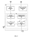
- FIG. 5 is a functional block diagram of a filter coefficient computation unit suitable for use in the coefficient generation unit of FIG. 3 in accordance with a non-limiting example of implementation of the invention
- FIG. 6 is a block diagram of a data structure including a set of cross-correlation data elements in accordance with a non-limiting example of implementation of the invention.
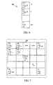
- FIG. 7 shows an auto-correlation matrix data structure in accordance with a non-limiting example of implementation of the invention.
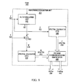
- FIG. 8 is a functional block diagram of a performance evaluation unit suitable for use in the filter adaptation unit of FIG. 2 in accordance with a non-limiting example of implementation of the invention
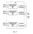
- FIG. 9 is a functional block diagram of a standard deviation computation unit suitable for use in the performance evaluation unit of FIG. 8 in accordance with a non-limiting example of implementation;
- FIG. 10 is a flow diagram showing a process for generating a set of performance data elements in accordance with a specific example of implementation of the invention.
- FIG. 11 is a functional block diagram of a noise reduction unit suitable for use in the filter adaptation unit of FIG. 2 in accordance with a non-limiting example of implementation of the invention
- FIG. 12 is a flow diagram showing a process implemented by the noise reduction unit for generating a new set of filter coefficients in accordance with a specific example of implementation of the invention.
- FIG. 13 is a block diagram of an apparatus for generating a set of filter coefficients in accordance with a specific example of implementation of the invention.
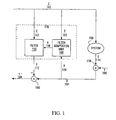
- FIG. 1 shows a time adaptive system 170 in accordance with an embodiment of the present invention.
- the time adaptive system 170 is used to remove unwanted components of a return signal Z 102 from a forward signal Y 106 .
- the return signal Z 102 passes through a system 150 and emerges in the form of a noise signal E 114 which corrupts the forward signal Y 106 , resulting in a corrupted forward signal X 104 .
- this corruption process may be modelled as a sample-by-sample addition performed by a conceptual adder 118 .
- each sample of the corrupted forward signal X 104 is the sum of a component due to the (clean) forward signal Y 106 and another component due to the noise signal E 114 where the noise signal E 114 is correlated to the return signal Z 102 .
- a non-limiting use of the time adaptive system 170 is in the context of acoustical echo cancellation, for example, in a hands-free telephony system that includes a loudspeaker and a microphone.
- the forward signal Y 106 is a locally produced speech signal which is injected into the microphone (represented by conceptual adder 118 )
- the return signal Z 102 is a remotely produced speech signal which is output by the loudspeaker
- the system 150 is a room or car interior
- the noise signal E 114 is a reverberated version of the return signal Z 102 which enters the same microphone used to pick up the forward signal Y 106 .
- the corrupted forward signal X 104 is the sum of the signals input to the microphone, including the clean forward signal Y 106 as well as the reverberation represented by the noise signal E 114 .
- the time adaptive system 170 is in the context of electric echo cancellation, for example, where the echo is caused by an analog/digital conversion on the transmission channel rather than by a signal reverberation in a closed space.
- the forward signal Y 106 is a locally produced speech signal which travels on the forward path of the communication channel
- the return signal Z 102 is a remotely produced speech signal which travels on the return path of the communication channel
- the system 150 is an analog/digital conversion unit
- the noise signal E 114 is a reflected version of the return signal Z 102 which travels on the same forward path of the communication channel as the forward signal Y 106 .
- the corrupted forward signal X 104 is the sum of the clean forward signal Y 106 as well as the noise signal E 114 .
- a filter 110 To cancel the corruptive effect of the noise signal E 114 on the forward signal Y 106 , there is provided a filter 110 , suitably embodied as an adaptive digital filter.
- the filter 110 taps the return signal Z 102 (which feeds the system 150 ) and applies a filtering operation thereto.
- a filtering operation can be performed by a finite impulse response (FIR) filter that produces a filtered signal F 112 .
- FIR finite impulse response
- the filter 110 includes a plurality N of taps at which delayed versions of the return signal Z 102 are multiplied by respective filter coefficients, whose values are denoted h j , 0 ⁇ j ⁇ N ⁇ 1.
- the N products are added together to produce the filter output at time T.
- the filtered signal F 112 at a given instant in time is a weighted sum of the samples of the return signal Z 102 at various past instances.
- the filter coefficients h j are computed by a filter adaptation unit 100 configured to receive the return signal Z 102 and the corrupted forward signal X 104 .
- the manner in which the filter adaptation unit 100 processes these signals to compute the filter coefficients h j is described in greater detail herein below.
- the optimal filter coefficients are obtained by solving an optimisation problem whose object it is to minimise, from among all possible combinations of filter coefficients h j , the mean square difference between instantaneous values of the resultant signal Y* 108 and the clean forward signal Y 106 .
- the actual value of the minimum mean-square error is typically not as important as the value of the optimal filter coefficients that allow such minimum to be reached.
- Equation 9 Equation 9
- Equation 9 Equation 9
- Equation 12 Equation 12
- Equation 15 we can separate the filter function defined by the set of filter coefficients h 1 [j], 0 ⁇ j ⁇ N ⁇ 1 into two components.
- the set of filter coefficients h 1 [j], 0 ⁇ j ⁇ N ⁇ 1 have a different performance depending on the frequency components of signal Z 102 .
- signal Z 102 having energy mainly in the 0 to 2 kHz frequency range and only low energy in the 2 to 4 kHz range
- signal X 104 having the opposite behavior namely low energy in the 0 to 2 kHz range and energy mainly in the 2 to 4 kHz frequency range.
- the energy of the error function resulting from the use of the filter coefficients h 1 [j], 0 ⁇ j ⁇ N ⁇ 1 will be low in the 0 to 2 kHz frequency range, and high in the 2 to 4 kHz frequency range.
- a result of the above is that if signal Z 102 includes at some instance of time components having energy in the 2 to 4 kHz range, the use of the filter coefficients may have some undesirable effects due to the energy of the error signals in that range such as for example to amplify signal Z 102 in those frequency bands.
- the inventors have made the unexpected discovery that by using the error function of the filter, it is possible to provide an new set of filter coefficients which may reduce some undesirable effects described above.
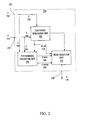
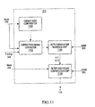
- FIG. 2 depicts the filter adaptation unit 100 in greater detail.
- the filter adaptation unit 100 includes a first input 252 for receiving a sequence of samples of a first signal Z 102 , a second input 254 for receiving a sequence of samples of a second signal X 104 , a coefficient generation unit 200 , a performance evaluation unit 202 , a noise reduction unit 210 and an output 256 for releasing an output signal indicative of a set of filter coefficients H 116 .
- the coefficient generation unit 200 receives the first signal Z 102 and the second signal X 104 from the first input 252 and the second input 254 respectively.
- the coefficient generation unit 200 is operative to generate a set of filter coefficients Hnew 206 at least in part on the basis of the first signal Z 102 and the second signal X 104 .
- the coefficient generation unit 200 applies a least squares method on the first signal 102 and second signal 104 to derive a first set of filter coefficients Hnew 206 .
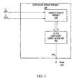
- FIG. 3 shows a specific non-limiting implementation of the coefficient generation unit 200 .
- the coefficient generation unit 200 includes a context update module 300 and a filter coefficient computation unit 302 .
- the context update module 300 receives the sequence of samples of the first signal Z 102 and the sequence of samples of the second signal X 104 .
- the context update module 300 generates and maintains contextual information for the first signal Z 102 and the second signal X 104 .
- the context update module 300 maintains sufficient contextual information about signals Z 102 and X 104 to be able to derive E[ z k z k T ] t and E[x k z k ] t for the current time t.
- This contextual information is then used by the filter coefficient computation unit 302 to generate the set of filter coefficients Hnew 206 .
- the specific realization of the context update module 300 may vary from one implementation to the other without detracting from the spirit of the invention.
- the contextual information comprises a first set of data elements and a second set of data elements, where the first set of data elements is indicative of the auto-correlation of signal Z 102 E[ z k z k T ] t .
- the second set of data elements is a set of cross-correlation data elements E[x k k k ] t of the first signal Z 102 with the second signal X 104 .
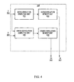
- FIG. 4 depicts the context update module 300 in greater detail.
- the context update module 300 includes an auto-correlation computing unit 400 and a cross-correlation computing unit 404 .
- the auto-correlation computing unit 400 generates a first set of data elements indicative of an auto-correlation data structure for the sequence of samples of the first signal Z 102 and is indicative of E[ z k z k T ] t since time 0.
- the first set of data elements can be represented by an N ⁇ N auto-correlation matrix A 1 700 of the type shown in FIG. 7 including N 2 entries.
- Matrix A 1 700 is also positive definite meaning that the inverse of matrix A 1 exists. Since matrix A 1 is an auto-correlation matrix, it will be positive definite when signal Z 102 is non-trivial.
- the N ⁇ N data elements of the auto-correlation matrix A 2 700 are stored in a data structure in an auto-correlation memory unit 402 . For each received sample of signal Z 102 , the contents of the auto-correlation memory unit 402 are updated.
- the generation of an auto-correlation matrix is well-known in the art to which this invention pertains and as such will not be described further here. There are many ways in which the auto-correlation matrix A 1 may be generated and the invention is not limited to the manner in which the auto-correlation matrix is obtained.
- the cross-correlation computing unit 404 computes a second set of data elements including a set of cross-correlation data elements between the signals Z 102 and X 104 indicative of E[x k z k ] t .
- x t ⁇ 1 is a new sample of the signal X 104 at time T
- z t ⁇ 1 is a new sample of Z 102 at time t
- M is the window size for the cross-correlation computation.
- E[x k z k ] t denotes a computation of the expected value of the cross-correlation between the first signal Z 102 and the second signal X 104 since time 0 (no sample) until the current sample at time t.
- E[x k z k ] t is a set of M cross-correlation data elements.
- the M cross-correlation data elements are stored in a data structure in a cross-correlation memory unit 406 .
- FIG. 6 shows the cross-correlation memory unit 406 storing a data structure in the form of a vector of M elements including the M cross-correlation data elements.
- the context update module 300 includes buffer modules for accumulating samples of signal Z 102 and signal X 104 .
- a plurality of samples of signal Z 102 and a plurality of samples of signal X 104 are accumulated in the buffers and the above described computations are effected for each sample of signal Z 102 and signal X 104 in the buffers.
- the auto-correlation matrix A 1 and the cross-correlation data elements in vector XZ may be computed in the frequency domain using FFT (Fast Fourier transform) techniques.
- the set of auto-correlation and cross-correlation data elements resulting from this computation are in the frequency or spectral domain.
- an Inverse Fourier Transform IFF
- IFF Inverse Fourier Transform
- the filter coefficient computation unit 302 makes use of the contextual information provided by the context update module 300 to generate a set of filter coefficients Hnew 206 .
- the frequency of the computation of the new set of filter coefficients Hnew 206 may vary from one implementation to the other without detracting from the spirit of the invention.
- FIG. 5 shows the filter coefficient computation unit 302 in greater detail in accordance with a non-limiting implementation.
- the filter coefficient computation unit 302 includes a matrix memory unit 500 for storing the N ⁇ N matrix A 1 , cross correlation memory unit 501 for storing cross-correlation vector XZ and a linear solver unit 560 .
- the matrix memory unit 500 of the filter coefficient computation unit 302 and the auto-correlation memory unit 402 of the context update module 300 are shown as separate components, it will be readily appreciated that they may be embodied in a same physical device and may share functional components without detracting from the spirit of the invention.
- the linear solver unit 560 processes the N ⁇ N auto-correlation matrix A 1 in matrix memory unit 500 in combination with cross-correlation vector XZ from the cross-correlation memory unit 501 to solve the following linear system for a set of filter coefficients in vector h 1 :
- a 1 ⁇ h 1 XZ Equation 18
- a 1 is an N ⁇ N positive definite symmetric matrix
- h 1 is an 1 ⁇ N vector
- XZ is an 1 ⁇ M vector.
- M>N then a vector h 1 of dimension 1 ⁇ N can be computed for subsets of N elements of vector “XZ”.
- computing the inverse of an N ⁇ N matrix is complex and requires significant computing resources especially when N is large.
- Several other well known methods have been developed to reduce the complexity of this computation. Examples of such methods include QR substitution, Cholesky decomposition, LU decomposition, Gauss-Jordan elimination, amongst others.
- Any suitable method for solving a set of linear equations may be used by the linear solver unit 560 to derive the vector h 1 including the set of filter coefficients.
- the reader is invited to refer to “Numerical Recipes in C: The Art of Scientific Computing”, William H. Press et al., Cambridge University Press (Chapter 2). The contents of this document are hereby incorporated by reference.
- the linear solver unit 560 makes use of the symmetric and positive definite characteristic of matrix A 1 by using Cholesky decomposition to solve the set of linear equations described by equation 18.
- the linear solver unit 560 includes a Cholesky decomposition unit 502 , a triangular matrix inverter 504 , a triangular matrix transpose inverter 505 and a matrix multiplier and solver 506 .
- the triangular matrix inverter 504 and the triangular matrix transpose inverter 505 process the lower triangular matrix W and its transpose respectively to generate the inverse of matrix W, namely W ⁇ 1 , and the inverse of the transpose, namely W Transpose ⁇ 1 .
- the linear solver unit 560 depicted in FIG. 5 includes a triangular matrix inverter 504 and triangular matrix transpose inverter 505 , these may be implemented by the same physical module without detracting from the spirit of the invention.
- the inverse of lower triangular matrix W requires fewer computations to compute than that of matrix A 1 .
- the matrix multiplier and solver unit 506 then solves the set of linear equations by substitution to obtain the set of filter coefficients in vector h 1 .
- Vector h 1 is then released at the output forming a signal including a set of N filter coefficients Hnew 206 .
- the generated set of filter coefficients Hnew 206 is then released at the output 356 of the coefficient generation unit 200 .
- the performance evaluation unit 202 characterizes the error function associated with adaptive filter 170 on the basis of the knowledge of the amplitude of the first signal Z 102 and of an estimate of the amplitude of the forward signal Y 106 .
- Equation 26 In order to characterize the error function of the adaptive filter 170 , a single tap filter is considered.
- error k z k ⁇ y k z k ⁇ z k Equation 28
- z k and y k are the kth samples of signals Z 102 and Y 106 respectively and error k is the kth component of the error function due to the kth samples of signals Z 102 and Y 106 .
- the error function can be considered as the sum of the errors added by the samples.
- the above described error function can be considered to be a random variable. In order to characterize this random variable, the mean and the variance (or alternatively the standard deviation) can be computed.
- the standard deviation of the error function can be expressed as the division of two terms namely the average error over time and the number of samples conditioned by the weight.
- an unbiased estimator of the variance (or standard deviation) of a set of sample is to be obtained, the sample number is reduced by “1” to obtain an unbiased effective sample set.
- equation 41 is used to characterize the standard deviation of the error function.
- signals Z 102 and Y 106 are divided spectrally into a set of frequency bands, where signal Z 102 and Y 106 can be considered to generally be substantially white within a given frequency band.
- the signals Z 102 and Y 106 (assuming a sampling rate of 8000 samples/sec and therefore a frequency spectrum from 0-4000 Hz) are divided into 257 frequency bands of 15.625 Hz each. Using heuristics measurements, this width has been found to be narrow enough that voice is approximately a white signal across each of the 15.625 Hz bands.
- the width of the bands may vary from one application to another without detracting from the spirit of the invention.
- the “whiteness” of the signal is a subjective quality and depends on the nature of the signals being processed.
- the error function is then characterized for each frequency band independently using the above described computation to estimate the mean (which is 0) and the standard deviation.
- the filter 110 in combination with adder 180 will generally eliminate most of signal Yc. Therefore, the energy of signal Y* 108 will be essentially equal to the energy of Yu which is less than or equal to the energy of signal Y 106 . Therefore, since signal Y 106 is not available, the energy of signal Y* 108 is used as an approximation of the energy of signal Y 106 .
- the performance evaluation unit 202 receives the first signal Z 102 , the second signal X 104 and the new set of filter coefficients Hnew 206 from the coefficient generation unit 200 .
- the performance evaluation unit 202 is operative to generate at least in part on the basis of the first signal Z 102 and the second signal X 104 a set of performance data elements Herror 208 associated to the new set of filter coefficients Hnew 206 .
- the performance evaluation unit 202 characterizes the error on a per-frequency band basis. Each performance data element in Herror 208 is a statistical estimate of the error function standard deviation for a respective frequency band.
- FIG. 8 shows a specific example of implementation of the performance evaluation unit 202 including a filter simulation unit 800 , an adder unit 802 , a first spectral calculator 806 , a second spectral calculator 804 and a per-band standard deviation computation unit 808 .
- the filter simulation unit 800 is suitably embodied as an adaptive digital filter and simulates the processing of filter 110 shown in FIG. 1 .
- the filter simulation unit 800 taps the return signal Z 102 , and receives the new set of filter coefficients Hnew 206 from the coefficient generation unit 200 .
- the filter simulation unit 800 applies a filtering operation corresponding to the filter coefficients Hnew 206 to the return signal Z 102 to produce filtered signal R 801 .
- the manner in which the filtering operative is applied was described with regard to filter 110 in FIG. 1 and therefore will not be repeated here.
- the output of the filter simulation unit 800 namely the filtered signal R 801 , is subtracted by adder unit 802 on a sample-by-sample basis from the corrupted forward signal X 104 to yield a signal denoted W 870 .
- Signal W 870 is an estimate of signal Y 106 ( FIG. 1 ) generated on the basis of the set of filter coefficients Hnew 206 .
- First spectral calculator 806 taps first signal Z 102 and divides the signal into a set of frequency bands.
- the first spectral calculator 806 applies a set of Fast Fourier Transform (FFT) of length (K ⁇ 1)*2, each Fast Fourier Transform (FFT) being applied to N of the samples of signal Z 102 , where N is the number of taps of the adaptive filter 170 .
- FFT Fast Fourier Transform
- Z SPECTRA is a data structure of t/N vectors each of size K, each vector being indicative of a spectral representation of N samples of signal z(t) and Z SPECTRA (j) is the spectral value of signal Z 102 associated to frequency band j.
- Z SPECTRA 810 is released by the second spectral calculator 804 .
- Second spectral calculator 804 taps the signal W 870 and divides the signal into a set of K frequency bands.
- the first spectral calculator 806 applies a set of Fast Fourier Transform (FFT) of length (K ⁇ 1)*2, each Fast Fourier Transform (FFT) being applied to N of the samples of signal W 870 where N is the number of taps of the adaptive filter 170 .
- FFT Fast Fourier Transform
- first spectral calculator 806 and second spectral calculator 804 are depicted as separate components in FIG. 8 , it will be readily appreciated that they may be embodied in a same physical device and may share functional components without detracting from the spirit of the invention.
- Herror[j] is the standard deviation of error function for frequency band j.
- the per-band standard deviation computation unit 808 also generates a per-band energy estimate for signal Z 102 , identified as Zenergy 240 in FIG. 8 .
- FIG. 9 shows a conceptual block diagram of the per-band standard deviation computation unit 808 .
- Each unit 900 also releases a data element Zenergy[j] indicative of the energy of signal Z 102 in frequency band j and Zenergy 240 is a set of K energy data elements.
- FIG. 8 is for the purpose of example only as many other implementations are possible.
- FIG. 10 shows an alternative non-limiting implementation of the performance evaluation unit 202 including a ZZ and WW auto-correlation generator 950 and a per-band standard deviation computation unit 952 .
- the auto-correlation of signal W 870 can be obtained from the auto-correlation of signal X 104 , the auto-correlation of signal Z 102 and the cross-correlation of signal Z 102 with signal X 104 .
- the ZZ and WW auto-correlation generator 950 is operative to generate a sequence of W t,SPECTRA [j] ⁇ W t,SPECTRA [j] auto-correlation data elements, shown as WW 956 in FIG. 10 , on the basis of the relationship described in equation 38 above and a sequence of Z t,SPECTRA [j] ⁇ Z t,SPECTRA [j] auto-correlation data elements, shown as ZZ 954 in FIG. 10 .
- the ZZ and WW auto-correlation generator 950 may be implemented in a number of ways and the specific implementation is not a limiting element of the invention and will not be described in further detail herein as it will be readily apparent to the person skilled in the art.
- Herror 208 and Zenergy 240 are released by the performance evaluation unit 202 and provided to the noise reduction unit 210 depicted in greater detail in FIG. 11 .
- Noise Reduction Unit 210 Noise Reduction Unit 210
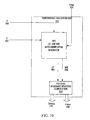
- FIG. 11 shows a specific example of implementation of the noise reduction unit 210 including an energy band comparator 1100 , a correction signal generator 1102 , an auto-correlation insertion unit 1104 and a filter coefficient computation unit 1106 .
- the energy band comparator 1100 determines for each frequency band in the set of K frequency bands whether the performance of the first set of filter coefficients Hnew 206 is satisfactory or unsatisfactory for that frequency band.
- the amplitude threshold may vary from one application to the other. In a non-limiting example of implementation, the threshold is selected based on the maximum amount of correlation that can be expected between the Z 102 and X 104 signals. If the error standard deviation value exceeds this amount then it can be deduced that the filter 110 may be added more correlation to signal X 104 than was initially present which is an undesirable behavior.
- a maximum value of 0.5 ( ⁇ 6 dB) is used as the threshold value for all frequencies.
- the correction signal generator 1102 receives the performance indicators from the energy band comparator 1100 , the Herror 208 from the performance evaluation unit 202 and the Z energy value 240 and generates a correction signal for each frequency band associated to a performance indicator indicative of an unsatisfactory performance.
- the energy of the correction signal is a function of the standard deviation of the error function and of the energy of signal Z 102 within the same frequency band.
- each correction signal is a signal of energy correction_signal[j] and having its energy substantially within the frequency band for which it was generated.
- corrections signal including a single frequency are generated by the correction signal generator, where the frequency is within the corresponding frequency band.
- the functionality implemented by the energy band comparator 1100 and the correction signal generator 1102 may be combined into a single operation implemented by a single functional module.
- the use of a Performance[j] data structure is omitted.
- the auto-correlation insertion unit 1104 receives the set of correction signals from the correction signal generator 1102 as well as the auto-correlation matrix from the auto-correlation memory unit 500 (shown in FIG. 5 ), referred to as the initial auto-correlation matrix.
- the auto-correlation insertion unit 1104 is operative to modify the initial auto-correlation matrix on the basis of the set of correction signals received.
- an auto-correlation is performed over N samples of the correction signal in order to generate an N ⁇ N auto-correlation matrix.
- This generates a set of auto-correlation matrices, one matrix for each correction signal in the set of the correction signals.
- a matrix addition is performed between the set of correlation matrices associated to the set of correction signals and the initial auto-correlation matrix A 1 obtained from the auto-correlation of signal Z 102 .
- a modified auto-correlation matrix A 2 1110 is generated.
- Matrix A 2 as matrix A 1 , is symmetric and positive definite.
- the filter computation unit 1106 makes use of the modified correlation matrix A 2 1110 and the cross-correlation data elements from the cross-correlation memory unit 501 ( FIG. 5 ) and generates a second set of filter represented by a vector h 2 .
- Any suitable method for solving a set of linear equations may be used to derive vector h 2 , where vector h 2 includes the second set of filter coefficients.
- the reader is invited to refer to “Numerical Recipes in C: The Art of Scientific Computing”, William H. Press et al., Cambridge University Press (Chapter 2). The contents of this document are hereby incorporated by reference.
- the new set of filter coefficients h 2 is released as signal H 116 at the output 356 of the coefficient adaptation unit 100 for use by filter 110 .
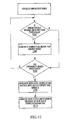
- step 1202 for each frequency band in the set of K frequency bands, the error amplitude received in Herror 208 is compared to a threshold value for that frequency band. If the error amplitude for that frequency band exceeds the threshold value, at step 1206 , a correction signal within that frequency band is generated. Following step 1206 , or alternatively if condition 1202 is answered in the negative, the system verifies at condition 1204 whether all the frequency bands have been processed. If there are remaining unprocessed frequency bands, the system returns to step 1202 .
- a modified auto-correlation matrix A 2 is generated on the basis of auto-correlation matrix A 1 and the set of correction signals generated at step 1206 .
- a new set of filter coefficients H 116 is computed on the basis of the modified auto-correlation matrix A 2 .
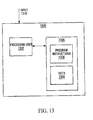
- the above-described process for producing a set of filter coefficients can be implemented on a general purpose digital computer of the type depicted in FIG. 13 , including a processing unit 1302 and a memory 1304 connected by a communication bus.
- the memory includes data 1308 and program instructions 1306 .
- the processing unit 1302 is adapted to process the data 1308 and the program instructions 1306 in order to implement the functional blocks described in the specification and depicted in the drawings.
- the digital computer 1300 may also comprise an I/O interface for receiving or sending data elements to external devices.
- the I/O interface may be used for receiving the first signal Z 102 and the second signal X 104 .
- the above-described process for producing a set of filter coefficients can be implemented on a dedicated hardware platform where electrical/optical components implement the functional blocks described in the specification and depicted in the drawings. Specific implementations may be realized using ICs, ASICs, DSPs, FPGA or other suitable hardware platform. It will be readily appreciated that the hardware platform is not a limiting component of the invention.
Landscapes
- Filters That Use Time-Delay Elements (AREA)
Abstract
Description
- 1. United States Patent Application entitled, “Method and Apparatus for Generating a Set of Filter Coefficients for a Time Updated Adaptive Filter”, filed on the same date as the instant application by Awad T. et al.
- 2. United States Patent Application entitled, “Method and Apparatus for Providing an Error Characterization Estimate of an Impulse Response Derived using Least Squares”, filed on the same date as the instant application by Awad T. et al.
- 3. United States Patent Application entitled, “Method and Apparatus for Generating a Set of Filter Coefficients”, filed on the same date as the instant application by Awad T. et al.
The contents of the above noted documents are hereby incorporated by reference.
A 1 ·h 1 =
A 2 ·h 2 =
where
-
- t is the current sample time;
- ft is the value of the filtered
signal F 112 at time t; - hj is the value of the jth filter coefficient;
- zk is a sample of the
return signal Z 102 at time k; and - N is the length (i.e., the number of taps) of the
filter 110.
For convenience,equation 1 may be represented in matrix form as follows:
where the underscore indicates a vector or matrix, where the superscript “T” denotes the transpose (not to be confused with the sample time “t” used as a subscript) and where:
The output of thefilter 110, namely the filteredsignal F 112, is subtracted on a sample-by-sample basis from the corruptedforward signal X 104 to yield an estimate, denoted Y* 108, of the cleanforward signal Y 106. In a desirable situation, the filter coefficients hj will be selected so as to cause the resultant signal Y* 108 to be “closer” to the cleanforward signal Y 106 than corruptedforward signal X 104. For at least one optimal combination of filter coefficients, the resultant signal Y* 108 will be at its “closest” to the cleanforward signal Y 106.
where E[∘], denotes the expectation of the quantity “◯” over a subset of time up until the current sample time t. For the purpose of this specific example, the expression E[∘], will denote the summation of the quantity “◯” over a subset of time up until the current sample time t. Another commonly used notation is Σ[∘]t. Therefore, for the purpose of this example the expressions E[∘]t and Σ[∘]t are used interchangeably.
Now, from
y* k =x k −f k =x k −h k T z k Equation 7
and
x k =y k +e k. Equation 8
Therefore, the problem stated in Equation 4 becomes:
Expanding the term in square brackets, one obtains:
(x k −h T z k)2 =x k 2−2x k h T z k+( h T z k)2. Equation 10
Taking the expected value of both side of equation 8, one obtains:
E[(x k −h T z k)2]t =E[x k 2]t−2E[x k h T z k]t +E[h T z k z k T h], Equation 11
Minimizing the above quantity leads to a solution for which the resultant signal Y* 108 will be at its minimum and likely at its “closest” to the clean
Thus, an “optimal” set of filter coefficients h1 solves the set of equations defined by:
E[z kz k T]th 1=E[xkz k]t. Equation 13
E[z k z k T]t h 1 =E[(y k +e 1) z k]t.
E[z k z k T]t h 1 =E[e k z k]t .+E[y k z k]t Equation 14
E[z k z k T]t error_function*=E=[y k z k]t. Equation 15
E[z k z k T]t h 1=E[xk z k]t. Equation 13
The
A1=A1 T
XZ[j] t =XZ[j] t−1 +z t−1−j x t−1 for j=0 . . . M−1 Equation 17
where t≧M.
A 1 ·h 1 =XZ Equation 18
h=A 1 −1 ·XZ
where
A 1 ·A 1 −1 =I Equation 19
where I is an N×N identity matrix.
A1h1=XZ Equation 20
A=W·W Transpose Equation 21
solving for y
y=W−1XZ Equation 22
The matrix multiplier and
solving for h
h1=WTranspose−1y Equation 23
Wy=AZ Equation 24
and
WTranposeh1=y Equation 25
can be done as well to derive vector h1.
E[z k z k T]t error_function*=E[yk z k]t. Equation 15
where
-
- t is the current sample time;
- zk is a sample of the
return signal Z 102 at time k; and - yk is a sample of the
return signal Y 106 at time k;
where zk and yk are the kth samples of
If the error components inserted at each pair of samples are equal to one another an are assigned equal weight, standard deviation of the error function after t samples can be expressed by the following expression:
where wi is a weight value associated to a given error component. The square root of the number of samples conditioned by the weight, which corresponds to √t of Equation 31, can be given by:
Therefore the standard deviation computation can be reduced to the following expression:
In a least squares context, the weight wk of the error for each sample k is zkzk. Therefore, in the current specific example, the standard deviation of the error function can be expressed as follows:
which can be reduced to the following:
In statistics, it is well known that when an unbiased estimator of the variance (or standard deviation) of a set of sample is to be obtained, the sample number is reduced by “1” to obtain an unbiased effective sample set. The effective sample set can be expressed by:
Therefore the standard deviation computation can be reduced as follows:
In a least square context, the weight wk of the error for each sample k is zkzk. Therefore, in this second specific example, the standard deviation of the error function can be expressed as follows:
For the purpose of a specific implementation, equation 41 is used to characterize the standard deviation of the error function.
where z[j] and y[j] is the amplitude of the component of
Yenergy=Yc energy+Yu energy Equation 43
where WSPECTRA is a data structure of t/N vectors each of size K, each vector being indicative of a spectral representation of N samples signal
where Herror[j] is the performance data element for frequency band j and
Note that Wt,SPECTRA[j]×Wt,SPECTRA[j] is the ith component of the auto-correlation of signal W 470 in frequency band j. Note that:
where {circle around (x)} denotes a convolution operation. As can be seen from the above equation, the auto-correlation of
if Herror[j]>Ethreshold[j]
Performance[j]=unsatisfactory
else Performance[j]=satisfactory Equation 54
where Ethreshold[j] is indicative of an amplitude threshold value for frequency band j and Performance[j] is a performance indicator for frequency band j. The amplitude threshold may vary from one application to the other. In a non-limiting example of implementation, the threshold is selected based on the maximum amount of correlation that can be expected between the
where a correction signal for band j has an energy correction_signal[j] computed by the above equation and energy in frequency band j. The term correction_signal[j], for j=0 . . . K−1, in the above equation is indicative of a set of K correction signals, where each correction signal is associated to a respective frequency band. In a specific example of implementation, each correction signal is a signal of energy correction_signal[j] and having its energy substantially within the frequency band for which it was generated. For the purpose of simplicity, corrections signal including a single frequency, are generated by the correction signal generator, where the frequency is within the corresponding frequency band.
A2 h 2=B Equation 57
There are many known methods that can be used to solve linear systems of the type described by the above equations. Examples of such methods include direct matrix inversion, QR substitution, Cholesky decomposition, LU decomposition, Gauss-Jordan elimination, amongst others. Any suitable method for solving a set of linear equations may be used to derive vector h2, where vector h2 includes the second set of filter coefficients. For more information regarding methods for solving sets of linear equations, the reader is invited to refer to “Numerical Recipes in C: The Art of Scientific Computing”, William H. Press et al., Cambridge University Press (Chapter 2). The contents of this document are hereby incorporated by reference.
Claims (33)
Priority Applications (2)
| Application Number | Priority Date | Filing Date | Title |
|---|---|---|---|
| US09/925,247 US6965640B2 (en) | 2001-08-08 | 2001-08-08 | Method and apparatus for generating a set of filter coefficients providing adaptive noise reduction |
| PCT/CA2002/001143 WO2003015274A1 (en) | 2001-08-08 | 2002-07-24 | Method and apparatus for generating a set of filter coefficients providing adaptive noise reduction |
Applications Claiming Priority (1)
| Application Number | Priority Date | Filing Date | Title |
|---|---|---|---|
| US09/925,247 US6965640B2 (en) | 2001-08-08 | 2001-08-08 | Method and apparatus for generating a set of filter coefficients providing adaptive noise reduction |
Publications (2)
| Publication Number | Publication Date |
|---|---|
| US20030072362A1 US20030072362A1 (en) | 2003-04-17 |
| US6965640B2 true US6965640B2 (en) | 2005-11-15 |
Family
ID=25451444
Family Applications (1)
| Application Number | Title | Priority Date | Filing Date |
|---|---|---|---|
| US09/925,247 Expired - Lifetime US6965640B2 (en) | 2001-08-08 | 2001-08-08 | Method and apparatus for generating a set of filter coefficients providing adaptive noise reduction |
Country Status (2)
| Country | Link |
|---|---|
| US (1) | US6965640B2 (en) |
| WO (1) | WO2003015274A1 (en) |
Cited By (3)
| Publication number | Priority date | Publication date | Assignee | Title |
|---|---|---|---|---|
| WO2003015272A1 (en) | 2001-08-08 | 2003-02-20 | Octasic Inc. | Method and apparatus for providing an error characterization estimate of an impulse response derived using least squares |
| US20070263714A1 (en) * | 2006-05-09 | 2007-11-15 | Bois Karl J | Determination of filter weights |
| US20080198914A1 (en) * | 2007-02-15 | 2008-08-21 | Massachusetts Institute Of Technology | Architecture for Systolic Nonlinear Filter Processors |
Families Citing this family (5)
| Publication number | Priority date | Publication date | Assignee | Title |
|---|---|---|---|---|
| US6999509B2 (en) * | 2001-08-08 | 2006-02-14 | Octasic Inc. | Method and apparatus for generating a set of filter coefficients for a time updated adaptive filter |
| US6970896B2 (en) | 2001-08-08 | 2005-11-29 | Octasic Inc. | Method and apparatus for generating a set of filter coefficients |
| JP4916394B2 (en) * | 2007-07-03 | 2012-04-11 | 富士通株式会社 | Echo suppression device, echo suppression method, and computer program |
| JP6215527B2 (en) * | 2012-02-02 | 2017-10-18 | 旭化成エレクトロニクス株式会社 | Physical quantity measuring apparatus and physical quantity measuring method |
| US10939205B2 (en) * | 2018-04-19 | 2021-03-02 | Utah State University | Echo cancelation using convolutive blind source separation |
Citations (30)
| Publication number | Priority date | Publication date | Assignee | Title |
|---|---|---|---|---|
| GB2164828A (en) | 1984-09-21 | 1986-03-26 | Int Standard Electric Corp | A method of reducing echo in a digital switching system and a digital hybrid therefor |
| US5062102A (en) | 1988-12-01 | 1991-10-29 | Nec Corporation | Echo canceller with means for determining filter coefficients from autocorrelation and cross-correlation coefficients |
| US5117418A (en) | 1990-11-09 | 1992-05-26 | Intelligent Modem Corporation | Frequency domain adaptive echo canceller for full-duplex data transmission |
| US5200915A (en) | 1990-06-12 | 1993-04-06 | Nec Corporation | Device for rapidly solving a symmetric linear system on a supercomputer |
| US5329587A (en) | 1993-03-12 | 1994-07-12 | At&T Bell Laboratories | Low-delay subband adaptive filter |
| US5375147A (en) | 1991-08-21 | 1994-12-20 | Fujitsu Limited | Jitter compensating device |
| US5442569A (en) | 1993-06-23 | 1995-08-15 | Oceanautes Inc. | Method and apparatus for system characterization and analysis using finite element methods |
| EP0709958A1 (en) | 1994-10-31 | 1996-05-01 | AT&T Corp. | Adaptive finite impulse response filtering method and apparatus |
| US5526426A (en) | 1994-11-08 | 1996-06-11 | Signalworks | System and method for an efficiently constrained frequency-domain adaptive filter |
| US5630154A (en) | 1994-10-11 | 1997-05-13 | Hughes Aircraft Company | Programmable systolic array system arranged in a found arrangement for passing data through programmable number of cells in a time interleaved manner |
| US5790598A (en) | 1996-03-01 | 1998-08-04 | Her Majesty The Queen In Right Of Canada | Block decision feedback equalizer |
| EP0872962A2 (en) | 1997-04-18 | 1998-10-21 | Nokia Mobile Phones Ltd. | Echo cancelling using foreground and background filters |
| US5889857A (en) | 1994-12-30 | 1999-03-30 | Matra Communication | Acoustical echo canceller with sub-band filtering |
| US5912966A (en) * | 1996-08-01 | 1999-06-15 | Northern Telecom Limited | Enhanced echo canceller for digital cellular application |
| US5974377A (en) | 1995-01-06 | 1999-10-26 | Matra Communication | Analysis-by-synthesis speech coding method with open-loop and closed-loop search of a long-term prediction delay |
| EP0982861A2 (en) | 1998-08-25 | 2000-03-01 | STMicroelectronics, Inc. | Method and apparatus for reducing convergence time |
| US6035312A (en) | 1997-02-13 | 2000-03-07 | Nec Corporation | Adaptive filter |
| US6151358A (en) | 1999-08-11 | 2000-11-21 | Motorola, Inc. | Method and apparatus, and computer program for producing filter coefficients for equalizers |
| US6246773B1 (en) * | 1997-10-02 | 2001-06-12 | Sony United Kingdom Limited | Audio signal processors |
| US6396872B1 (en) | 1998-06-11 | 2002-05-28 | Nec Corporation | Unknown system identification method by subband adaptive filters and device thereof |
| US6437932B1 (en) | 1996-05-16 | 2002-08-20 | Lsi Logic Corporation | Decision based time-varying equalizers |
| US20020114445A1 (en) * | 2000-12-05 | 2002-08-22 | Jacob Benesty | Method and apparatus for network echo cancellation using a proportionate normalized least mean squares algorithm |
| US20030031242A1 (en) | 2001-08-08 | 2003-02-13 | Awad Thomas Jefferson | Method and apparatus for generating a set of filter coefficients for a time updated adaptive filter |
| US20030074381A1 (en) * | 2001-08-08 | 2003-04-17 | Awad Thomas Jefferson | Method and apparatus for generating a set of filter coefficients |
| US20030084079A1 (en) * | 2001-08-08 | 2003-05-01 | Awad Thomas Jefferson | Method and apparatus for providing an error characterization estimate of an impulse response derived using least squares |
| US6622118B1 (en) * | 2001-03-13 | 2003-09-16 | Alphatech, Inc. | System and method for comparing signals |
| US6735304B2 (en) * | 2000-03-03 | 2004-05-11 | Nec Corporation | Adaptive filter and echo canceller using the same |
| US6744886B1 (en) | 1999-01-06 | 2004-06-01 | Lucent Technologies Inc. | Adaptive filter utilizing proportional affine projection algorithm |
| US6757384B1 (en) * | 2000-11-28 | 2004-06-29 | Lucent Technologies Inc. | Robust double-talk detection and recovery in a system for echo cancelation |
| US6768796B2 (en) | 2001-02-05 | 2004-07-27 | 3Com Corporation | System and method for echo cancellation |
-
2001
- 2001-08-08 US US09/925,247 patent/US6965640B2/en not_active Expired - Lifetime
-
2002
- 2002-07-24 WO PCT/CA2002/001143 patent/WO2003015274A1/en not_active Ceased
Patent Citations (31)
| Publication number | Priority date | Publication date | Assignee | Title |
|---|---|---|---|---|
| GB2164828A (en) | 1984-09-21 | 1986-03-26 | Int Standard Electric Corp | A method of reducing echo in a digital switching system and a digital hybrid therefor |
| US5062102A (en) | 1988-12-01 | 1991-10-29 | Nec Corporation | Echo canceller with means for determining filter coefficients from autocorrelation and cross-correlation coefficients |
| US5200915A (en) | 1990-06-12 | 1993-04-06 | Nec Corporation | Device for rapidly solving a symmetric linear system on a supercomputer |
| US5117418A (en) | 1990-11-09 | 1992-05-26 | Intelligent Modem Corporation | Frequency domain adaptive echo canceller for full-duplex data transmission |
| US5375147A (en) | 1991-08-21 | 1994-12-20 | Fujitsu Limited | Jitter compensating device |
| US5329587A (en) | 1993-03-12 | 1994-07-12 | At&T Bell Laboratories | Low-delay subband adaptive filter |
| US5442569A (en) | 1993-06-23 | 1995-08-15 | Oceanautes Inc. | Method and apparatus for system characterization and analysis using finite element methods |
| US5630154A (en) | 1994-10-11 | 1997-05-13 | Hughes Aircraft Company | Programmable systolic array system arranged in a found arrangement for passing data through programmable number of cells in a time interleaved manner |
| EP0709958A1 (en) | 1994-10-31 | 1996-05-01 | AT&T Corp. | Adaptive finite impulse response filtering method and apparatus |
| US5526426A (en) | 1994-11-08 | 1996-06-11 | Signalworks | System and method for an efficiently constrained frequency-domain adaptive filter |
| US5889857A (en) | 1994-12-30 | 1999-03-30 | Matra Communication | Acoustical echo canceller with sub-band filtering |
| US5974377A (en) | 1995-01-06 | 1999-10-26 | Matra Communication | Analysis-by-synthesis speech coding method with open-loop and closed-loop search of a long-term prediction delay |
| US5790598A (en) | 1996-03-01 | 1998-08-04 | Her Majesty The Queen In Right Of Canada | Block decision feedback equalizer |
| US6437932B1 (en) | 1996-05-16 | 2002-08-20 | Lsi Logic Corporation | Decision based time-varying equalizers |
| US5912966A (en) * | 1996-08-01 | 1999-06-15 | Northern Telecom Limited | Enhanced echo canceller for digital cellular application |
| US6035312A (en) | 1997-02-13 | 2000-03-07 | Nec Corporation | Adaptive filter |
| EP0872962A2 (en) | 1997-04-18 | 1998-10-21 | Nokia Mobile Phones Ltd. | Echo cancelling using foreground and background filters |
| US6246773B1 (en) * | 1997-10-02 | 2001-06-12 | Sony United Kingdom Limited | Audio signal processors |
| US6396872B1 (en) | 1998-06-11 | 2002-05-28 | Nec Corporation | Unknown system identification method by subband adaptive filters and device thereof |
| US6483872B2 (en) | 1998-08-25 | 2002-11-19 | Stmicroelectronics, Inc. | Method and apparatus for reducing convergence time |
| EP0982861A2 (en) | 1998-08-25 | 2000-03-01 | STMicroelectronics, Inc. | Method and apparatus for reducing convergence time |
| US6744886B1 (en) | 1999-01-06 | 2004-06-01 | Lucent Technologies Inc. | Adaptive filter utilizing proportional affine projection algorithm |
| US6151358A (en) | 1999-08-11 | 2000-11-21 | Motorola, Inc. | Method and apparatus, and computer program for producing filter coefficients for equalizers |
| US6735304B2 (en) * | 2000-03-03 | 2004-05-11 | Nec Corporation | Adaptive filter and echo canceller using the same |
| US6757384B1 (en) * | 2000-11-28 | 2004-06-29 | Lucent Technologies Inc. | Robust double-talk detection and recovery in a system for echo cancelation |
| US20020114445A1 (en) * | 2000-12-05 | 2002-08-22 | Jacob Benesty | Method and apparatus for network echo cancellation using a proportionate normalized least mean squares algorithm |
| US6768796B2 (en) | 2001-02-05 | 2004-07-27 | 3Com Corporation | System and method for echo cancellation |
| US6622118B1 (en) * | 2001-03-13 | 2003-09-16 | Alphatech, Inc. | System and method for comparing signals |
| US20030031242A1 (en) | 2001-08-08 | 2003-02-13 | Awad Thomas Jefferson | Method and apparatus for generating a set of filter coefficients for a time updated adaptive filter |
| US20030074381A1 (en) * | 2001-08-08 | 2003-04-17 | Awad Thomas Jefferson | Method and apparatus for generating a set of filter coefficients |
| US20030084079A1 (en) * | 2001-08-08 | 2003-05-01 | Awad Thomas Jefferson | Method and apparatus for providing an error characterization estimate of an impulse response derived using least squares |
Non-Patent Citations (4)
| Title |
|---|
| Adaptive filters; Theory and Applications/B. Farhang-Boroujeny. John Wiley & Sons Ltd. (chapter 12, pp. 413-437). |
| Deisher, M.E. et al., "Practical Considerations in the Implementation of a Frequency-Domain Adaptive Noise Canceller", IEEE Transactions on Circuits and Systems, II; Analog and Digital Signal Processing, IEEE Inc. New York, US, vol. 41, No. 2, Feb. 1, 1994, pp. 164-168, XP000443037. |
| Linear Predictive Spectral Shaping for Acoustical Echo Cancellation. Sanro Zlobec. Department of Electrical Engineering, McGill University, Montreal, Nov. 1995. |
| Numerical recipes in C: the art of scientific computing/William H. Press. Cambridge University Press (chapters 1-2, pp. 1-99). |
Cited By (5)
| Publication number | Priority date | Publication date | Assignee | Title |
|---|---|---|---|---|
| WO2003015272A1 (en) | 2001-08-08 | 2003-02-20 | Octasic Inc. | Method and apparatus for providing an error characterization estimate of an impulse response derived using least squares |
| US20070263714A1 (en) * | 2006-05-09 | 2007-11-15 | Bois Karl J | Determination of filter weights |
| US7746924B2 (en) * | 2006-05-09 | 2010-06-29 | Hewlett-Packard Development Company, L.P. | Determination of filter weights |
| US20080198914A1 (en) * | 2007-02-15 | 2008-08-21 | Massachusetts Institute Of Technology | Architecture for Systolic Nonlinear Filter Processors |
| US8005176B2 (en) * | 2007-02-15 | 2011-08-23 | Massachusetts Institute Of Technology | Architecture for systolic nonlinear filter processors |
Also Published As
| Publication number | Publication date |
|---|---|
| WO2003015274A1 (en) | 2003-02-20 |
| US20030072362A1 (en) | 2003-04-17 |
Similar Documents
| Publication | Publication Date | Title |
|---|---|---|
| US6970896B2 (en) | Method and apparatus for generating a set of filter coefficients | |
| US7171436B2 (en) | Partitioned block frequency domain adaptive filter | |
| CN109727604B (en) | Frequency domain echo cancellation method and computer storage medium for speech recognition front-end | |
| US7058185B1 (en) | Acoustic echo and noise cancellation | |
| CN107749304B (en) | Method and device for continuously updating coefficient vector of finite impulse response filter | |
| US8594320B2 (en) | Hybrid echo and noise suppression method and device in a multi-channel audio signal | |
| US5568558A (en) | Adaptive noise cancellation device | |
| US7684559B2 (en) | Acoustic echo suppressor for hands-free speech communication | |
| EP1715669A1 (en) | A method for removing echo in an audio signal | |
| US20060002546A1 (en) | Multi-input channel and multi-output channel echo cancellation | |
| US6957240B2 (en) | Method and apparatus for providing an error characterization estimate of an impulse response derived using least squares | |
| JPH08288890A (en) | Method and device for adaptive type filtering | |
| US6999509B2 (en) | Method and apparatus for generating a set of filter coefficients for a time updated adaptive filter | |
| US6965640B2 (en) | Method and apparatus for generating a set of filter coefficients providing adaptive noise reduction | |
| Shin et al. | Adaptive interference canceler for narrowband and wideband interferences using higher order statistics | |
| EP1314247B1 (en) | Partitioned block frequency domain adaptive filter | |
| Derkx et al. | New constraining method for partitioned block frequency-domain adaptive filters | |
| US7231234B2 (en) | Method and apparatus for reducing echo in a communication system | |
| Valero et al. | A state-space partitioned-block adaptive filter for echo cancellation using inter-band correlations in the Kalman gain computation | |
| Liu et al. | A variable step-size pre-filter-bank adaptive algorithm | |
| Avargel et al. | Identification of linear systems with adaptive control of the cross-multiplicative transfer function approximation | |
| Morales et al. | Adaptive Filtering Techniques for Forensic Audio | |
| Fan | A multi-band acoustic echo canceller for vehicular handsfree telephone | |
| Chennamsetti et al. | Speech enhancement using Fast Hartley Transform |
Legal Events
| Date | Code | Title | Description |
|---|---|---|---|
| AS | Assignment |
Owner name: OCTASIC, INC., CANADA Free format text: ASSIGNMENT OF ASSIGNORS INTEREST;ASSIGNORS:AWAD, THOMAS JEFFERSON;GERVAIS, PASCAL MARCEL;LAURENCE, MARTIN;REEL/FRAME:012081/0559 Effective date: 20010808 |
|
| STCF | Information on status: patent grant |
Free format text: PATENTED CASE |
|
| FEPP | Fee payment procedure |
Free format text: PAYOR NUMBER ASSIGNED (ORIGINAL EVENT CODE: ASPN); ENTITY STATUS OF PATENT OWNER: LARGE ENTITY |
|
| FPAY | Fee payment |
Year of fee payment: 4 |
|
| FEPP | Fee payment procedure |
Free format text: PAT HOLDER NO LONGER CLAIMS SMALL ENTITY STATUS, ENTITY STATUS SET TO UNDISCOUNTED (ORIGINAL EVENT CODE: STOL); ENTITY STATUS OF PATENT OWNER: LARGE ENTITY |
|
| FPAY | Fee payment |
Year of fee payment: 8 |
|
| FPAY | Fee payment |
Year of fee payment: 12 |