US6946614B2 - Circuit breakers - Google Patents
Circuit breakers Download PDFInfo
- Publication number
- US6946614B2 US6946614B2 US10/380,292 US38029203A US6946614B2 US 6946614 B2 US6946614 B2 US 6946614B2 US 38029203 A US38029203 A US 38029203A US 6946614 B2 US6946614 B2 US 6946614B2
- Authority
- US
- United States
- Prior art keywords
- interrupter
- actuator
- dielectric material
- solid dielectric
- earthed
- Prior art date
- Legal status (The legal status is an assumption and is not a legal conclusion. Google has not performed a legal analysis and makes no representation as to the accuracy of the status listed.)
- Expired - Fee Related
Links
- 239000003989 dielectric material Substances 0.000 claims abstract description 16
- 239000007787 solid Substances 0.000 claims abstract description 13
- 239000004020 conductor Substances 0.000 claims abstract description 11
- 239000002184 metal Substances 0.000 claims description 8
- 238000009421 internal insulation Methods 0.000 claims description 5
- 230000008878 coupling Effects 0.000 abstract description 2
- 238000010168 coupling process Methods 0.000 abstract description 2
- 238000005859 coupling reaction Methods 0.000 abstract description 2
- 238000001514 detection method Methods 0.000 abstract description 2
- 238000009413 insulation Methods 0.000 description 6
- IJGRMHOSHXDMSA-UHFFFAOYSA-N Atomic nitrogen Chemical compound N#N IJGRMHOSHXDMSA-UHFFFAOYSA-N 0.000 description 4
- 239000007789 gas Substances 0.000 description 3
- 238000012544 monitoring process Methods 0.000 description 3
- 238000009833 condensation Methods 0.000 description 2
- 230000005494 condensation Effects 0.000 description 2
- 238000011109 contamination Methods 0.000 description 2
- 239000007788 liquid Substances 0.000 description 2
- 238000012423 maintenance Methods 0.000 description 2
- 229910052757 nitrogen Inorganic materials 0.000 description 2
- 230000015556 catabolic process Effects 0.000 description 1
- 238000006731 degradation reaction Methods 0.000 description 1
- 230000000694 effects Effects 0.000 description 1
- 239000012777 electrically insulating material Substances 0.000 description 1
- 230000007613 environmental effect Effects 0.000 description 1
- 239000003822 epoxy resin Substances 0.000 description 1
- 239000011810 insulating material Substances 0.000 description 1
- 239000012774 insulation material Substances 0.000 description 1
- 229920000647 polyepoxide Polymers 0.000 description 1
- 239000002986 polymer concrete Substances 0.000 description 1
- 238000004804 winding Methods 0.000 description 1
Images


Classifications
-
- H—ELECTRICITY
- H01—ELECTRIC ELEMENTS
- H01H—ELECTRIC SWITCHES; RELAYS; SELECTORS; EMERGENCY PROTECTIVE DEVICES
- H01H33/00—High-tension or heavy-current switches with arc-extinguishing or arc-preventing means
- H01H33/02—Details
- H01H33/027—Integrated apparatus for measuring current or voltage
-
- H—ELECTRICITY
- H01—ELECTRIC ELEMENTS
- H01H—ELECTRIC SWITCHES; RELAYS; SELECTORS; EMERGENCY PROTECTIVE DEVICES
- H01H33/00—High-tension or heavy-current switches with arc-extinguishing or arc-preventing means
- H01H33/60—Switches wherein the means for extinguishing or preventing the arc do not include separate means for obtaining or increasing flow of arc-extinguishing fluid
- H01H33/66—Vacuum switches
- H01H33/662—Housings or protective screens
- H01H33/66207—Specific housing details, e.g. sealing, soldering or brazing
- H01H2033/6623—Details relating to the encasing or the outside layers of the vacuum switch housings
-
- H—ELECTRICITY
- H01—ELECTRIC ELEMENTS
- H01H—ELECTRIC SWITCHES; RELAYS; SELECTORS; EMERGENCY PROTECTIVE DEVICES
- H01H33/00—High-tension or heavy-current switches with arc-extinguishing or arc-preventing means
- H01H33/60—Switches wherein the means for extinguishing or preventing the arc do not include separate means for obtaining or increasing flow of arc-extinguishing fluid
- H01H33/66—Vacuum switches
- H01H33/666—Operating arrangements
Definitions
- the present invention is concerned with circuit breakers, particularly of the type comprising current sensing devices or current transformers to detect primary current overloads or short-circuits for monitoring and protection.
- Circuit breakers at medium voltages usually need to employ current sensing devices or transformers to detect primary current overloads and short-circuits for monitoring and protection. In indoor applications, these may be incorporated in the equipment of which the circuit breaker is a component part On the other hand, in outdoor applications, particularly in rural electrification schemes, where the circuit breaker is often used in overhead line applications, the current sensor or transformer is preferably incorporated as an integral part of the circuit breaker.
- a current sensor such as a ring-type current sensor or transformer
- Typical examples of conventional use are shown in FIGS. 1 and 2 .
- the interrupting device could be typically a vacuum or gas switch.
- FIG. 1 usually requires some form of additional liquid or gaseous insulation, such as oil or SF6, to keep the size of the circuit breaker to acceptable levels and also to ensure that the internal components are maintained free of moisture and contamination.
- additional liquid or gaseous insulation such as oil or SF6
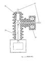
- FIG. 2 A more recent design is depicted generally in FIG. 2 .
- the current transformer or sensor is mounted at the side of the switch and electrically in series with it. This example uses a vacuum switch and current transformer encapsulated in solid insulation.
- the current flowing through the device is carried by conductors 1 , encapsulated in suitable electrically insulating material 2 , such as epoxy resin or polymer concrete.
- suitable electrically insulating material 2 such as epoxy resin or polymer concrete.
- Connection 9 , flexible connection 4 and switch 7 provide the internal conducting path. Operation to open or close the switch 7 is performed by actuator 8 and lever 5 .
- the integrity of the internal insulation surfaces is maintained by using SF6 gas or oil.
- the current flowing through the device is similarly carried by conductors 21 and switch 22 through current transformer 23 .
- some form of controlled environment is required, such as SF6 gas or dry nitrogen.
- SF6 gas or dry nitrogen it is necessary to protect the internal insulation surfaces by using a controlled environment, leading to additional costs and also risks of degradation and failure if the controlled environment is dissipated due to failure of seals and leakage.
- the invention aims to provide a circuit breaker that does not suffer from the above disadvantages.
- the invention provides a circuit breaker comprising an assembly consisting of a circuit interrupter mounted coaxially within a current sensor or transformer, said assembly being encapsulated within solid dielectric material and supported at one end of an earthed electrically conductive tube whose other end is mounted on an earthed metal housing.
- the circuit breaker is preferably a vacuum interrupter.
- the circuit breaker is conveniently operated by means of a mechanical linkage of insulating material extending between said interrupter and an actuator, said linkage being mounted externally of the metal tube and said solid dielectric material.
- the operating mechanism for the circuit interrupter may be selected from any of the group consisting of a permanent magnet actuator, a spring-type actuator, a hydraulic actuator, a pneumatic actuator or a solenoid actuator.
- the mechanical linkage preferably comprises a rod of solid dielectric material.
- the ends of the rod preferably pass through flexible bellows, at one end into a space within the dielectric material encapsulating the circuit interrupter/current sensor or transformer assembly, and at the other end into the said earthed housing.
- FIG. 1 is a typical prior art circuit breaker
- FIG. 2 is a later development of a prior art circuit breaker
- FIG. 3 is an example of a circuit breaker in accordance with the present invention.
- circuit interrupter 31 is mounted coaxially within the current sensor or transformer 32 .
- the combination is encapsulated within the main electrically insulating body 33 , as shown in FIG. 3 .
- the interrupter and current sensor or transformer in this way, the secondary winding can be supported by an earthed metal tube 41 .
- earthed metal tube 41 There is then no internal insulation exposed to high voltage stress, either between parts at high voltage and earth or across the terminals of the circuit breaker. This removes completely the need for additional protection and regular maintenance.
- an interrupter 31 is connected between conductors 36 , 37 constituting the main current path. Coaxially located around the interrupter 32 is a current sensor or transformer 32 .
- the interrupter 31 has an armature 31 ′ connected via a flexible coupling 44 to one of the main current path conductors 36 .
- Both the interrupter 31 and the current sensor or transformer are encapsulated in a housing 33 of dielectric material.
- the sensor or transformer 32 is supported at one end of an electrically conductive tubular body 41 , eg of metal, whose other end is electrically and mechanically connected to an electrically conductive housing 44 .
- Secondary wires 43 from the current sensor or transformer 32 can be fed through the metal tube 41 to a suitable terminal board (not shown) mounted in the housing 44 .
- the housing 44 and the metal tube 44 are connected to an earth terminal (not shown).
- An actuator 42 is located within the housing 44 and is coupled to a linkage 40 , preferably comprising a dielectric rod.
- a linkage 40 preferably comprising a dielectric rod.
- One end of the rod 40 is coupled to the actuator, for example via a spiral spring, and the other end is coupled to a bell crank mechanism 35 .
- the bell crank mechanism 35 is also coupled to the armature 31 ′ of the interrupter 31 .
- circuitry on the terminal board senses the overload condition and activates the actuator 42 in the housing 44 so as to tend to pull the linkage 40 in direction A.
- the pull on the link 40 is translated into movement of the bell crank 35 so as to tend to pull the armature 31 ′ of the interrupter 31 in a rightwards direction (in FIG. 3 ), whereby to open the interrupter 31 .
- the circuit breaker opens the main current path through conductors 36 , 37 in response to detection of the overload current.
- the interrupter 31 is restored by the action of the actuator 42 pushing the linkage 40 in direction B to close the interrupter 31 via the bell crank lever 35 , whereby to close the circuit breaker and restore it to its dormant position.
- the linkage 40 is preferably terminated mechanically by flexible bellows 38 and 39 to provide weather protection where the linkage or drive rod 40 enters the housings 33 and 44 .
- the push-pull motion can be achieved by using a suitable operating mechanism, such as a permanent magnet actuator as described in UK Patent No 2297429 or any other form of suitable actuator 42 , such as spring, hydraulic, pneumatic or solenoid types.
- a suitable operating mechanism such as a permanent magnet actuator as described in UK Patent No 2297429 or any other form of suitable actuator 42 , such as spring, hydraulic, pneumatic or solenoid types.
Landscapes
- Gas-Insulated Switchgears (AREA)
- Breakers (AREA)
- Driving Mechanisms And Operating Circuits Of Arc-Extinguishing High-Tension Switches (AREA)
- Emergency Protection Circuit Devices (AREA)
- Recrystallisation Techniques (AREA)
- Ignition Installations For Internal Combustion Engines (AREA)
- Valve Device For Special Equipments (AREA)
- Control Of Vending Devices And Auxiliary Devices For Vending Devices (AREA)
- Percussive Tools And Related Accessories (AREA)
- Organic Insulating Materials (AREA)
Abstract
Description
Claims (4)
Applications Claiming Priority (3)
| Application Number | Priority Date | Filing Date | Title |
|---|---|---|---|
| WOPCT/GB00/03516 | 2000-09-13 | ||
| PCT/GB2000/003516 WO2002023570A1 (en) | 2000-09-13 | 2000-09-13 | Circuit breaker with coaxial current sensor |
| PCT/GB2001/004103 WO2002023687A1 (en) | 2000-09-13 | 2001-09-13 | Circuit breakers |
Publications (2)
| Publication Number | Publication Date |
|---|---|
| US20040050820A1 US20040050820A1 (en) | 2004-03-18 |
| US6946614B2 true US6946614B2 (en) | 2005-09-20 |
Family
ID=9885677
Family Applications (1)
| Application Number | Title | Priority Date | Filing Date |
|---|---|---|---|
| US10/380,292 Expired - Fee Related US6946614B2 (en) | 2000-09-13 | 2001-09-13 | Circuit breakers |
Country Status (11)
| Country | Link |
|---|---|
| US (1) | US6946614B2 (en) |
| EP (1) | EP1317787B1 (en) |
| CN (1) | CN1217463C (en) |
| AT (1) | ATE284575T1 (en) |
| AU (2) | AU2000270305A1 (en) |
| BR (1) | BR0113846A (en) |
| DE (1) | DE60107699D1 (en) |
| ES (1) | ES2237596T3 (en) |
| MX (1) | MXPA03002137A (en) |
| PT (1) | PT1317787E (en) |
| WO (2) | WO2002023570A1 (en) |
Cited By (4)
| Publication number | Priority date | Publication date | Assignee | Title |
|---|---|---|---|---|
| US20070091970A1 (en) * | 2002-09-30 | 2007-04-26 | Mcgraw-Edison Company | Solid Dielectric Encapsulated Interrupter with Reduced Corona Levels and Improved BIL |
| US8497446B1 (en) | 2011-01-24 | 2013-07-30 | Michael David Glaser | Encapsulated vacuum interrupter with grounded end cup and drive rod |
| US20150235790A1 (en) * | 2014-02-20 | 2015-08-20 | Cooper Technologies Company | Modular Switchgear Insulation System |
| USD800667S1 (en) | 2015-02-20 | 2017-10-24 | Cooper Technologies Company | Modular switchgear insulation device |
Families Citing this family (8)
| Publication number | Priority date | Publication date | Assignee | Title |
|---|---|---|---|---|
| US7215228B2 (en) * | 2001-06-01 | 2007-05-08 | Hubbell Incorporated | Circuit interrupting device with a turnbuckle and weld break assembly |
| BRPI0617804B1 (en) * | 2005-10-28 | 2018-07-31 | S & C Electric Co. | CIRCUIT SWITCH ASSEMBLY |
| DE102007003131A1 (en) | 2007-01-17 | 2008-07-24 | Siemens Ag | Circuit breaker and method for its manufacture |
| US8054606B2 (en) | 2008-06-10 | 2011-11-08 | Eaton Corporation | Remote operation of a motor control center subunit disconnect |
| CN103681093A (en) * | 2013-12-03 | 2014-03-26 | 沈阳昊诚电气股份有限公司 | Outdoor solid insulation switch |
| CN104091719A (en) * | 2014-06-09 | 2014-10-08 | 沈阳昊诚电气股份有限公司 | Outdoor insulation switch pole |
| US9852851B2 (en) | 2014-10-21 | 2017-12-26 | General Electric Company | Molded case circuit breaker with current sensing unit |
| US20250336627A1 (en) * | 2024-04-26 | 2025-10-30 | EMA Electromechanics, Inc. | Vacuum high voltage live tank circuit breaker free of fluid |
Citations (5)
| Publication number | Priority date | Publication date | Assignee | Title |
|---|---|---|---|---|
| US3562457A (en) | 1967-11-14 | 1971-02-09 | Allis Chalmers Mfg Co | Combined vacuum circuit breaker and current transformer device |
| US5191180A (en) * | 1990-07-19 | 1993-03-02 | Fuji Electric Co., Ltd. | Gas-insulated switchgear including a vacuum switch, operating mechanism and plural bellows |
| US5350892A (en) * | 1991-11-20 | 1994-09-27 | Gec Alsthom Sa | Medium tension circuit-breaker for indoor or outdoor use |
| US5585611A (en) | 1994-03-31 | 1996-12-17 | Abb Power T&D Company Inc. | Interrupter assembly |
| US5729888A (en) | 1993-04-29 | 1998-03-24 | Lindsey Manufacturing Company | Method of making an integrated electrical system |
-
2000
- 2000-09-13 WO PCT/GB2000/003516 patent/WO2002023570A1/en not_active Ceased
- 2000-09-13 AU AU2000270305A patent/AU2000270305A1/en not_active Abandoned
-
2001
- 2001-09-13 US US10/380,292 patent/US6946614B2/en not_active Expired - Fee Related
- 2001-09-13 ES ES01967483T patent/ES2237596T3/en not_active Expired - Lifetime
- 2001-09-13 AT AT01967483T patent/ATE284575T1/en not_active IP Right Cessation
- 2001-09-13 AU AU2001287858A patent/AU2001287858A1/en not_active Abandoned
- 2001-09-13 MX MXPA03002137A patent/MXPA03002137A/en active IP Right Grant
- 2001-09-13 PT PT01967483T patent/PT1317787E/en unknown
- 2001-09-13 EP EP01967483A patent/EP1317787B1/en not_active Expired - Lifetime
- 2001-09-13 CN CN018155723A patent/CN1217463C/en not_active Expired - Fee Related
- 2001-09-13 BR BR0113846-4A patent/BR0113846A/en not_active IP Right Cessation
- 2001-09-13 DE DE2001607699 patent/DE60107699D1/en not_active Expired - Lifetime
- 2001-09-13 WO PCT/GB2001/004103 patent/WO2002023687A1/en not_active Ceased
Patent Citations (5)
| Publication number | Priority date | Publication date | Assignee | Title |
|---|---|---|---|---|
| US3562457A (en) | 1967-11-14 | 1971-02-09 | Allis Chalmers Mfg Co | Combined vacuum circuit breaker and current transformer device |
| US5191180A (en) * | 1990-07-19 | 1993-03-02 | Fuji Electric Co., Ltd. | Gas-insulated switchgear including a vacuum switch, operating mechanism and plural bellows |
| US5350892A (en) * | 1991-11-20 | 1994-09-27 | Gec Alsthom Sa | Medium tension circuit-breaker for indoor or outdoor use |
| US5729888A (en) | 1993-04-29 | 1998-03-24 | Lindsey Manufacturing Company | Method of making an integrated electrical system |
| US5585611A (en) | 1994-03-31 | 1996-12-17 | Abb Power T&D Company Inc. | Interrupter assembly |
Cited By (6)
| Publication number | Priority date | Publication date | Assignee | Title |
|---|---|---|---|---|
| US20070091970A1 (en) * | 2002-09-30 | 2007-04-26 | Mcgraw-Edison Company | Solid Dielectric Encapsulated Interrupter with Reduced Corona Levels and Improved BIL |
| US7887732B2 (en) * | 2002-09-30 | 2011-02-15 | Cooper Technologies Company | Method of reducing electrical discharge in a structure |
| US8497446B1 (en) | 2011-01-24 | 2013-07-30 | Michael David Glaser | Encapsulated vacuum interrupter with grounded end cup and drive rod |
| US20150235790A1 (en) * | 2014-02-20 | 2015-08-20 | Cooper Technologies Company | Modular Switchgear Insulation System |
| US9640350B2 (en) * | 2014-02-20 | 2017-05-02 | Cooper Technologies Company | Modular switchgear insulation system |
| USD800667S1 (en) | 2015-02-20 | 2017-10-24 | Cooper Technologies Company | Modular switchgear insulation device |
Also Published As
| Publication number | Publication date |
|---|---|
| AU2001287858A1 (en) | 2002-03-26 |
| WO2002023687A1 (en) | 2002-03-21 |
| BR0113846A (en) | 2003-06-03 |
| ES2237596T3 (en) | 2005-08-01 |
| WO2002023570A1 (en) | 2002-03-21 |
| EP1317787A1 (en) | 2003-06-11 |
| US20040050820A1 (en) | 2004-03-18 |
| AU2000270305A1 (en) | 2002-03-26 |
| PT1317787E (en) | 2005-05-31 |
| MXPA03002137A (en) | 2005-04-19 |
| ATE284575T1 (en) | 2004-12-15 |
| CN1455976A (en) | 2003-11-12 |
| CN1217463C (en) | 2005-08-31 |
| DE60107699D1 (en) | 2005-01-13 |
| EP1317787B1 (en) | 2004-12-08 |
Similar Documents
| Publication | Publication Date | Title |
|---|---|---|
| US5585611A (en) | Interrupter assembly | |
| CN100530465C (en) | Vacuum interrupter and system and method for mitigating electric field distortions therein | |
| US7239490B2 (en) | Medium voltage vacuum circuit interrupter | |
| US6946614B2 (en) | Circuit breakers | |
| US7724489B2 (en) | Circuit breaker with high speed mechanically-interlocked grounding switch | |
| US3522404A (en) | Totally enclosed component | |
| US6927356B2 (en) | Enclosed switchgear | |
| KR102313514B1 (en) | Reduced size fault breakers | |
| US3025375A (en) | Electric circuit breaker having a sealed interrupting unit | |
| US6723940B1 (en) | Encapsulated magnetically actuated vacuum interrupter with integral bushing connector | |
| CA2180587C (en) | Bushing assembly with interrupter for electrical equipment | |
| US11348747B2 (en) | Switch assembly with energy harvesting | |
| EP1050059A1 (en) | Instantaneous trip power transformer | |
| CN214590159U (en) | Pole-mounted combined electrical apparatus | |
| CN207381850U (en) | A kind of on-pole switch equipment built in disconnecting switch | |
| CN114600213A (en) | Voltage sensor for electrical switchgear and electrical switchgear including the same | |
| CA2410703A1 (en) | Combination of a vacuum interruption device and oil-filled transformer | |
| EP1192631B1 (en) | Encapsulated magnetically actuated vacuum interrupter with integral bushing connector | |
| JP4266094B2 (en) | Gas insulated instrument transformer | |
| CN112615294A (en) | Pole-mounted combined electrical apparatus | |
| JPS6261220A (en) | Gas breaker with arrestor |
Legal Events
| Date | Code | Title | Description |
|---|---|---|---|
| AS | Assignment |
Owner name: BRIAN MCKEAN ASSOCIATES, LTD., UNITED KINGDOM Free format text: ASSIGNMENT OF ASSIGNORS INTEREST;ASSIGNORS:MCKEAN, BRIAN;MCKEAN, NIGEL T.;MCKEAN, BRIAN A.R.;REEL/FRAME:013987/0144 Effective date: 20030902 |
|
| FPAY | Fee payment |
Year of fee payment: 4 |
|
| FPAY | Fee payment |
Year of fee payment: 8 |
|
| REMI | Maintenance fee reminder mailed | ||
| LAPS | Lapse for failure to pay maintenance fees |
Free format text: PATENT EXPIRED FOR FAILURE TO PAY MAINTENANCE FEES (ORIGINAL EVENT CODE: EXP.) |
|
| STCH | Information on status: patent discontinuation |
Free format text: PATENT EXPIRED DUE TO NONPAYMENT OF MAINTENANCE FEES UNDER 37 CFR 1.362 |
|
| FP | Lapsed due to failure to pay maintenance fee |
Effective date: 20170920 |