US691981A - Fuel-feeding attachment for furnaces. - Google Patents
Fuel-feeding attachment for furnaces. Download PDFInfo
- Publication number
- US691981A US691981A US4796001A US1901047960A US691981A US 691981 A US691981 A US 691981A US 4796001 A US4796001 A US 4796001A US 1901047960 A US1901047960 A US 1901047960A US 691981 A US691981 A US 691981A
- Authority
- US
- United States
- Prior art keywords
- fuel
- furnace
- furnaces
- plate
- jets
- Prior art date
- Legal status (The legal status is an assumption and is not a legal conclusion. Google has not performed a legal analysis and makes no representation as to the accuracy of the status listed.)
- Expired - Lifetime
Links
Images
Classifications
-
- F—MECHANICAL ENGINEERING; LIGHTING; HEATING; WEAPONS; BLASTING
- F23—COMBUSTION APPARATUS; COMBUSTION PROCESSES
- F23K—FEEDING FUEL TO COMBUSTION APPARATUS
- F23K3/00—Feeding or distributing of lump or pulverulent fuel to combustion apparatus
- F23K3/10—Under-feed arrangements
- F23K3/12—Under-feed arrangements feeding by piston
Definitions
- This invention relates to the mechanical feeding of fuel to steam-boiler and like furnaces, and refers more particularly to the type of stoking or fuel-feeding apparatus described in my former patent, No. 680,818, dated August 20, 1901.
- the jet apparatus is preferably in the form of a perforated pipe or pipes situated immediately over the furnacedoor, with the perforations pointing downward, and the guide-vane is preferably in the -form of a metal or other suitable plate adjustably mounted at an angle upon the back of the furnace-door.
- E E are the adjustable feed-distributing plates, and F the furnace.
- G is the defiector or guide-vane, adjustably mounted, by studs H, regulating-nut I, and screw J, upon the rear of the furnace-door K.
- the said plate may be provided with a centralprojectin g part nearits lower edge, after the style of a cow-catcher and as shown by dotted lines in Figs. l and 3.
- the angle of the plate G is readily altered to suit requirements.
- the plate may be in halves and the respective halves be hinged to the opposite edges of the doorway, as shown in Fig. 4; but I prefer the arrangement aforesaid.
Description
im. s9|,9a|. Pafented 1an. 28,1902..
W. G. STONES. FUEL FEE'DING ATTACHMENT FOB FUHNACES.
(Application led Feb. 19, 1901.) (No Model.)
UNITE STATES y ATENT OFFICE.
VILL'IAM GRIMSIIA\V STONES, OF BLACKBURN, ENGLAND.
FUEL-FEEDING ATTACHMENT FOR FURNACES.
SPECIFICATION forming part of Letters PatentNo. 691,981, dated January 28, 1902. Application iiled February 19, 1901. Serial No. 47,96%. (No model.)
To all whom, if may concern:
Be it known that I, WILLIAM GRIMSHAW STONES, asubject of the King of Great Britain and Ireland, and a resident of Blackburn, near Manchester, England, have invented certain new and useful Improvements in Fuel- Feeding Attachments for Furnaces, of which the following -is a specification.
This invention'relates to the mechanical feeding of fuel to steam-boiler and like furnaces, and refers more particularly to the type of stoking or fuel-feeding apparatus described in my former patent, No. 680,818, dated August 20, 1901.
Its object is to provide means supplementary to the said stoking apparatus for insuring of the complete distribution and combustion of the finer portions of the fuel fed into the furnace by the stoker. To this end I employ at the front part of the furnace an arrangement of steam, air, or like blowing-jets supplied With air, steam, or both, from any suitable source and a deflector or guide-vane so disposed relatively to the jets and the area or Zonein which the fine fuel f alls within the furnace that when in operation the blowing-jets play against the guide-vane, and the guidevane in turn deflects or guides the currents against the falling fuel, which they carry forward and distribute over the furnace-grate, the range of distribution being variable by varying the force of the jets or by varying the angle or form of the guide-vane. The jet apparatus is preferably in the form of a perforated pipe or pipes situated immediately over the furnacedoor, with the perforations pointing downward, and the guide-vane is preferably in the -form of a metal or other suitable plate adjustably mounted at an angle upon the back of the furnace-door.
On the accompanying drawings I illustrate the preferred application of my invention, and with the aid of the reference characters marked thereon I will further describe my invention in relation thereto.
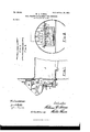
Figure l is a vertical section of a part of the mechanical stoking apparatus described in my said former application, the front end of one of the boiler-furnaces, and my present invention as applied hereto. Fig. 2 is an elevation of the said apparatus from a point feed boxes, and C one of the rotary feed-fans mounted on a rotating shaft D.
E E are the adjustable feed-distributing plates, and F the furnace.
According to my present invention G is the defiector or guide-vane, adjustably mounted, by studs H, regulating-nut I, and screw J, upon the rear of the furnace-door K.
L is the perforated air or steam pipe eX- tending across the front of the furnace above the plate G, closed at one end, supported by brackets M, and passing out at the opposite end to the outside, where it is supplied with steam or air under pressure. The holes N in the pipe L point downward toward the face of the plate, and the plate is of such a shape and lies at such an angle to the plane of the furnace-grate that with steam turned en and the jets playing against or upon the face of plate G they are deiected, as indicated by dotted lines in Fig. l, toward and over the furnace-grate. Therefore with the said pipe and plate situated immediately below the outlet-openings of the fan-boxes O and fuel being fed into the furnace the presence of the jets of steam and their force serve to carry or impel forward the liner particles of fuel and distribute the same over the furnace-grate in lieu of such fuel falling directly upon the dead-plate and accumulating thereon, as is likely to be the case without the jets. The
plate G maybe slightly arched or curved, as
shown in Fig. 3, so as to deflect the jets radially and the fuel radially or (and) the said plate may be provided with a centralprojectin g part nearits lower edge, after the style of a cow-catcher and as shown by dotted lines in Figs. l and 3. By the adjustment of nut I the angle of the plate G is readily altered to suit requirements.
While preferring the plateG to be attached to the furnace-door, so as to be moved out of the Way when the door is opened, I may hinge it to one edge of the furnace-doorwayand cause it to retire inwardly out vof the way,
either with the opening of the door or by hand.
In such connection the plate may be in halves and the respective halves be hinged to the opposite edges of the doorway, as shown in Fig. 4; but I prefer the arrangement aforesaid.
While illy-invention is advantageous in effecting the distribution of the ner particles of fuel, it will be seen that it is also useful by injecting steam or air into the furnace in promoting the combustion of the fuel and in preventing smoke, and although I have described my invention as applied to the construction of Stoker covered by my said previous application I wish it to be understood that I may apply it to other and like constructions of stokers.
What I claim is-
Priority Applications (1)
| Application Number | Priority Date | Filing Date | Title |
|---|---|---|---|
| US4796001A US691981A (en) | 1901-02-19 | 1901-02-19 | Fuel-feeding attachment for furnaces. |
Applications Claiming Priority (1)
| Application Number | Priority Date | Filing Date | Title |
|---|---|---|---|
| US4796001A US691981A (en) | 1901-02-19 | 1901-02-19 | Fuel-feeding attachment for furnaces. |
Publications (1)
| Publication Number | Publication Date |
|---|---|
| US691981A true US691981A (en) | 1902-01-28 |
Family
ID=2760520
Family Applications (1)
| Application Number | Title | Priority Date | Filing Date |
|---|---|---|---|
| US4796001A Expired - Lifetime US691981A (en) | 1901-02-19 | 1901-02-19 | Fuel-feeding attachment for furnaces. |
Country Status (1)
| Country | Link |
|---|---|
| US (1) | US691981A (en) |
-
1901
- 1901-02-19 US US4796001A patent/US691981A/en not_active Expired - Lifetime
Similar Documents
| Publication | Publication Date | Title |
|---|---|---|
| US749206A (en) | Fuel-feeding device | |
| US691981A (en) | Fuel-feeding attachment for furnaces. | |
| US5794548A (en) | Pneumatic bark distributor for continuous ash discharge stokers | |
| US1664082A (en) | Underfeed furnace | |
| US2158673A (en) | Overfeed stoker | |
| US1204631A (en) | Feeding and burning fine fuel. | |
| US1641470A (en) | Pulverized-coal system | |
| US717935A (en) | Fuel-feeding device. | |
| US730884A (en) | Fuel-feeding apparatus. | |
| US725090A (en) | Smoke-consuming furnace. | |
| US649211A (en) | Smokeless furnace. | |
| US753673A (en) | Apparatus for feeding fine fuel and air to furnaces. | |
| US524579A (en) | Fuel-feeding device | |
| US1924123A (en) | Means for feeding pulverized fuel to furnaces | |
| US880966A (en) | Consuming smoke in boiler-furnaces and the like. | |
| US690671A (en) | Smoke-consuming device. | |
| US2044308A (en) | Stoker mechanism | |
| US626981A (en) | Feeding device for steam-boiler furnaces | |
| US2271237A (en) | Distributor for stokers | |
| US1457339A (en) | Kiln and burner therefor | |
| US2131995A (en) | Stoker fuel distributor | |
| US967375A (en) | Automatic force-draft smoke-consumer. | |
| US729909A (en) | Forced-draft appliance for furnaces. | |
| US1437678A (en) | Comminuted-fuel carburetor | |
| US522059A (en) | Tucky |