US6906280B2 - Fast pulse nonthermal plasma reactor - Google Patents
Fast pulse nonthermal plasma reactor Download PDFInfo
- Publication number
- US6906280B2 US6906280B2 US10/395,047 US39504703A US6906280B2 US 6906280 B2 US6906280 B2 US 6906280B2 US 39504703 A US39504703 A US 39504703A US 6906280 B2 US6906280 B2 US 6906280B2
- Authority
- US
- United States
- Prior art keywords
- high voltage
- plasma reactor
- recited
- discharge cell
- discharge
- Prior art date
- Legal status (The legal status is an assumption and is not a legal conclusion. Google has not performed a legal analysis and makes no representation as to the accuracy of the status listed.)
- Expired - Fee Related
Links
Images


Classifications
-
- H—ELECTRICITY
- H05—ELECTRIC TECHNIQUES NOT OTHERWISE PROVIDED FOR
- H05H—PLASMA TECHNIQUE; PRODUCTION OF ACCELERATED ELECTRICALLY-CHARGED PARTICLES OR OF NEUTRONS; PRODUCTION OR ACCELERATION OF NEUTRAL MOLECULAR OR ATOMIC BEAMS
- H05H1/00—Generating plasma; Handling plasma
- H05H1/24—Generating plasma
- H05H1/2406—Generating plasma using dielectric barrier discharges, i.e. with a dielectric interposed between the electrodes
-
- H—ELECTRICITY
- H05—ELECTRIC TECHNIQUES NOT OTHERWISE PROVIDED FOR
- H05H—PLASMA TECHNIQUE; PRODUCTION OF ACCELERATED ELECTRICALLY-CHARGED PARTICLES OR OF NEUTRONS; PRODUCTION OR ACCELERATION OF NEUTRAL MOLECULAR OR ATOMIC BEAMS
- H05H2245/00—Applications of plasma devices
- H05H2245/10—Treatment of gases
- H05H2245/17—Exhaust gases
Definitions
- This invention pertains generally to for processing pollutant containing gases, and more particularly to nonthermal plasma reactors.
- VOCs volatile organic compounds
- RCRA U.S. Conservation and Recovery Act
- NPDES National Pollutant Discharge Elimination System
- NESHAPS National Emissions Standards for Hazardous Air Pollution regulations
- the present invention has recognized the prior art drawbacks, and has provided the below-disclosed solutions to one or more of the prior art deficiencies.
- the present invention can be used to effectively treat VOCs while meeting regulations in a timely and economical fashion.
- the present invention can be used to treat other air pollutants and hazardous/toxic chemicals in gases (e.g., acid rain precursors NOx and SOx, odor causing chemicals, chemical/biological warfare agents, and industrial emissions).
- gases e.g., acid rain precursors NOx and SOx, odor causing chemicals, chemical/biological warfare agents, and industrial emissions.
- NTP nonthermal plasma
- the present invention is a device that employs electrical discharges/nonthermal plasmas in a gaseous medium to destroy air pollutants or undesirable chemicals/chemical or biological agents, to process chemicals, or to synthesize chemical compounds.
- nonthermal plasmas the electrons are “hot”, while the ions and neutral species are “cold” which results in little waste enthalpy being deposited in a process gas stream. This is in contrast to thermal plasmas, where the electron, ion, and neutral-species energies are in thermal equilibrium (or “hot”) and considerable waste heat is deposited in the process gas.
- the NTP reactor is applied to gas streams containing hazardous/toxic, or other undesirable pollutants or contaminants and to gas streams that are to be processed (i.e., changed in chemical form or transformed into other useful products).
- a nonthermal plasma reactor includes a discharge cell and a charging assembly.
- the charging assembly provides plural high voltage pulses to the discharge cell.
- Each high voltage pulse has a rise time between one and ten nanoseconds and a duration between three and twenty nanoseconds.
- a nonthermal plasma reactor in another aspect of the present invention, includes a discharge cell and a first charging assembly and a second charging assembly that are electrically connected to the discharge cell.
- the charging assemblies alternatingly provide opposite polarity high voltage pulses to the reactor.
- a nonthermal plasma reactor in yet another aspect of the present invention, includes a first capacitor plate and a second capacitor plate. A dielectric layer is disposed between the first capacitor plate and the second capacitor plate. Further, a spark gap switch is electrically connected to the first capacitor plate and a first electrode is electrically connected to the second capacitor plate. A second electrode is slightly spaced from the first electrode and a dielectric layer is disposed adjacent to the first electrode. Moreover, a gas discharge gap is established between the dielectric layer and the second electrode. In this aspect of the present invention, the first capacitor plate and the second capacitor plate provide plural high voltage pulses to the discharge cell.
- a nonthermal plasma reactor in yet still another aspect of the present invention, includes a first capacitor plate, a second capacitor plate, and a first dielectric layer that is disposed therebetween.
- a first spark gap switch is electrically connected to the first capacitor plate.
- the reactor further includes a third capacitor plate, a fourth capacitor plate, and a second dielectric layer that is disposed therebetween. Further, a second spark gap switch is electrically connected to the third capacitor plate.
- a first electrode is electrically connected to the second capacitor plate and the fourth capacitor plate and a second electrode is slightly spaced from the first electrode.
- a dielectric layer is disposed adjacent to the first electrode and a gas discharge gap is established between the dielectric layer and the second electrode. The first capacitor plate, the second capacitor plate, the third capacitor plate, and the fourth capacitor plate alternatingly provide opposite polarity high voltage pulses to the reactor.
- a nonthermal plasma reactor in still yet another aspect of the present invention, includes a discharge cell and means for providing plural high voltage pulses to the discharge cell. Each high voltage pulse has a rise time of not more than ten nanoseconds.
- a method for treating pollutant containing gases includes providing a discharge cell. Plural high voltage pulses are provided to the discharge cell. Each high voltage pulse has a rise time of not more than ten nanoseconds.
- a method for treating pollutant containing gases comprises providing a discharge cell.
- Plural opposite polarity high voltage pulses are alternatingly provided to the discharge cell.
- Each opposite polarity high voltage pulse has a rise time of not more than ten nanoseconds.
- An object of the invention is to provide a relatively high degree of contaminant removal.
- Another object of the invention is to reduce contaminant removal costs.
- Another object of the invention is to provide more efficient chemical processing/synthesis.
- Another object of the invention is to provide for nonthermal treatment of pollutant containing gases.
- Another object of the invention is to provide for simultaneous destruction and removal of multiple pollutants.
- Another object of the invention is to eliminate the need for fuels or catalysts.
- Another object of the invention is to provide a broad dynamic range for treatment of both rich and lean streams.
- Another object of the invention is to provide for higher active species production efficiency with extremely short, high E/N pulses, where E/N is the reduced electric field strength when the process gas experiences electrical breakdown.
- FIG. 1 is a schematic diagram of electrical discharge streamers in a gas discharge gap between two electrodes.
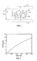
- FIG. 2 is a graph of average electron energy versus reduced electric field (E/N).
- FIG. 3 is a side view of a first embodiment of a nonthermal plasma reactor with the housing cut away for clarity.
- FIG. 4 is a schematic diagram of an electric circuit diagram representing the device shown in FIG. 3 .
- FIG. 5 is a schematic diagram of a resonant-charging circuit for the nonthermal plasma reactor shown in FIG. 3 .
- FIG. 6 is a graph of reduced electric field versus time.
- FIG. 7 is a graph of reactor power versus time.
- FIG. 8 is a side view of a second embodiment of a nonthermal plasma reactor with the housing cut away for clarity.
- FIG. 9 is a schematic diagram of a circuit utilizing capacitive transfer circuits.
- FIG. 1 through FIG. 9 the apparatus generally shown in FIG. 1 through FIG. 9 . It will be appreciated that the apparatus may vary as to configuration and as to details of the parts, and that the method may vary as to the specific steps and sequence, without departing from the basic concepts as disclosed herein.
- a positive electrode and a negative electrode are shown and designated 10 and 12 , respectively.
- a gas discharge gap 14 is established between the electrodes 10 , 12 .
- the gas discharge gap 14 has a width 16 .
- three non-limiting, exemplary discharge streamers 18 are shown between the electrodes 10 , 12 within the gas discharge gap 14 .
- Each discharge streamer 18 shown has a head 20 and a tail 22 .
- a voltage pulse can be applied across the electrodes 10 , 12 . If the applied voltage pulse rise time and pulse duration are comparable to the streamer transit time across the gap 14 , the drive circuit, described below, can influence the development of the discharge across the gap 14 . If the applied electric field rises fast enough, each discharge streamer head 20 can coalesce to create quasi-homogenous discharges. It is to be understood that quasi-homogenous discharges can have very favorable consequences. For example, the discharge operates for a larger fraction of its duration at a higher, and more favorable, reduced electric field, i.e., electric field divided by gas density (E/N). Further, the discharge operates at a higher average electron energy. FIG. 2 , for example, shows that the average electron energy increases with increasing reduced electric field for oxygen gas.
- E/N gas density
- FIG. 3 shows a non-limiting, exemplary embodiment of a nonthermal plasma (NTP) reactor, generally designated 50 .
- the reactor 50 includes a generally rectangular, box-shaped housing 52 in which a charging assembly 54 and a discharge cell 56 are disposed.
- the charging assembly 54 includes a first capacitor plate 58 and a second capacitor plate 60 .
- the first capacitor plate 58 rests on a first dielectric layer 62 (e.g., Mylar) which insulates it from the housing 52 .
- a second dielectric layer 64 is installed between the capacitor plates 58 , 60 .
- a spark gap switch 66 is connected to the first capacitor plate 58 .
- the discharge cell 56 includes a first electrode 68 and a second electrode 70 that are separated by a dielectric layer 72 .
- the dielectric layer 72 is made from a material such as glass.
- a gas discharge gap 74 is established between the electrodes 68 , 70 . It is to be understood that after the capacitor plates 58 , 60 are charged, the spark gap switch 66 can be used to control the electric pulse delivered across the electrodes 68 , 70 . It is to be understood that pollutant containing gas can be supplied to the gas discharge gap 74 where it can be treated as described in detail below.
- FIG. 4 an electric circuit representing the device shown in FIG. 3 is shown and is generally designated 100 .
- FIG. 4 shows that the circuit 100 includes a first electrode 102 and a second electrode 104 that are separated by a discharge gap 106 .
- FIG. 4 also shows that a first dielectric layer 108 and second dielectric layer 110 can be disposed between the electrodes 102 , 104 and that the discharge gap 106 can be established between the dielectric layers 108 , 110 .
- a first inductor 112 is connected parallel to the electrodes 102 , 104 .
- a first capacitor 114 and a second capacitor 116 are also installed in the circuit 100 such that they are connected in series to each other and the combination thereof is connected parallel to the first inductor 112 and the electrodes 102 , 104 .
- FIG. 4 also shows a second inductor 118 that is connected to the circuit 100 adjacent to the second capacitor 116 the second inductor 118 represents the inherent inductance of the spark gap switch 126 .
- the circuit 100 is connected to a power source 120 such as a direct current (DC) power source.
- a resistor 122 is connected between the power source 120 and the circuit 100 .
- the circuit 100 is also connected to ground 124 , e.g., at the second electrode 104 .
- the circuit 100 also includes a switch 126 , e.g. a spark gap switch as described above. It is to be understood that the above described circuit 100 can be used to create a fast-pulse nonthermal discharge between the electrodes 102 , 104 .
- FIG. 5 a resonant-charging circuit is shown and is generally designated 150 .
- FIG. 5 shows that the circuit 150 includes a discharge cell 152 having a first electrode 154 and a second electrode 156 separated by a discharge gap 158 .
- a first inductor 160 is installed in the circuit so that it is parallel to the electrodes 154 , 156 .
- a first capacitor 162 and a second capacitor 164 are connected in series to each other and the combination thereof is connected parallel to the first inductor 160 and the electrodes 154 , 156 .
- FIG. 5 further shows a transformer 166 installed in the circuit 150 .
- the transformer 166 includes a low voltage (input) side 168 and a high voltage (output) side 170 .
- the high voltage side 170 of the transformer 166 is installed in the circuit 150 so that it provides a high voltage signal to the capacitors 162 , 164 .
- FIG. 5 also shows a spark gap switch 172 is installed in the circuit parallel to the second capacitor 164 .
- the spark gap switch 172 is connected to ground 174 and can be used to control the electric pulses that are delivered to the discharge cell 152 between the electrodes 154 , 156 .
- a first diode 176 is installed in the circuit 150 between the spark gap switch 172 and the transformer 166 .
- the low voltage side 168 of the transformer 166 is connected to a power source 178 such as an AC power source.
- a second diode 180 and a resistor 182 are connected parallel to each other and the combination thereof is installed in series within the circuit 150 between the low voltage side 168 of the transformer 166 and the power source 178 .
- a second inductor 184 is connected in series with the second diode 180 and resistor 182 combination between the power source 178 and the second diode 180 and resistor 182 combination. It is to be understood that the above described circuit 150 can be used to create a fast-pulse nonthermal discharge between the electrodes 154 , 156 within the discharge cell 152 .
- FIG. 6 shows a reduced electric field waveform generated, e.g., by the reactor 50 shown in FIG. 3 with oxygen in the discharge cell 56 , i.e. within the gas discharge gap 74 .
- the waveform peaks at approximately one and eight-tenths of a nanosecond (1.8 ns). This is a direct result of a high voltage pulse having an extremely fast rise time and short duration.
- FIG. 7 shows an exemplary, non-limiting graph of the short-pulse electrical discharge power versus time, e.g., for the reactor 50 shown in FIG. 3 .
- the power peaks initially at approximately two and eight-tenths nanoseconds (2.8 ns) and as time elapses the amplitude of the power spikes decrease. Accordingly, very little power is wasted at times when electron temperature is low.
- the reactor 200 includes a generally rectangular, box-shaped housing 202 in which a first charging assembly 204 and a second charging assembly 206 are disposed. Each charging assembly 204 , 206 is connected to a discharge cell 208 that is disposed in the housing 202 between the charging assemblies 204 , 206 .
- FIG. 8 shows that the first charging assembly 204 includes a first capacitor plate 210 and a second capacitor plate 212 . The first capacitor plate 210 rests on a first dielectric layer 214 which insulates it from the housing 202 . Also, a second dielectric layer 216 is installed between the capacitor plates 210 , 212 . A spark gap switch 218 is connected to the first capacitor plate 210 .
- the second charging assembly 206 includes a first capacitor plate 220 and a second capacitor plate 222 .
- the first capacitor plate 220 rests on a first dielectric layer 224 which insulates it from the housing 202 .
- a second dielectric layer 226 is installed between the capacitor plates 220 , 222 .
- a spark gap switch 228 is connected to the first capacitor plate 220 .
- the discharge cell 208 includes a first electrode 230 and a second electrode 232 that are separated by a dielectric layer 234 .
- the dielectric layer 234 is made, e.g., from glass.
- a gas discharge gap 236 is established between the electrodes 230 , 232 . It is to be understood that the capacitor plates 210 , 212 of the first charging assembly 204 and the capacitor plates 220 , 222 of the second charging assembly 206 can be oppositely charged.
- the spark gap switches 218 , 228 can be alternatingly fired in order to alternatingly deliver opposite polarity pulses to the discharge cell 208 .
- FIG. 9 a circuit diagram utilizing capacitive transfer circuits is shown and is generally designated 250 .
- the circuit 250 includes a first electrode 252 and a second electrode 254 that are separated by a discharge gap 256 .
- FIG. 9 also shows that a first dielectric layer 258 and second dielectric layer 260 can be disposed between the electrodes 252 , 254 and that the discharge gap 256 can be established between the dielectric layers 258 , 260 .
- the circuit 250 includes a first capacitive-transfer circuit 262 and a second capacitive-transfer circuit 264 that provide pulses across the electrodes 252 , 254 within the discharge gap 256 .
- the first capacitive-transfer circuit 262 includes a storage capacitor 266 and a peaking capacitor 268 that are connected to the circuit 250 in series to each other and in parallel to the electrodes 252 , 254 .
- FIG. 9 also shows that the first capacitive-transfer circuit 262 is connected to a negative power source 270 .
- a first inductor 272 is installed between the power source 270 and the first capacitive-transfer circuit 262 .
- a second inductor 274 and a switch 276 are shown between the first inductor 272 and the peaking capacitor 268 . It is to be understood that the second inductor 274 shown in the first capacitive-transfer circuit 262 represents the inherent inductance of the switch 276 and the connections associated therewith.
- the second capacitive-transfer circuit 264 includes a storage capacitor 278 and a peaking capacitor 280 that are connected to the circuit 250 in series to each other and parallel to the electrodes 252 , 254 .
- FIG. 9 also shows that the second capacitive-transfer circuit 264 is connected to a positive power source 282 .
- a first inductor 284 is installed between the power source 282 and the second capacitive-transfer circuit 264 .
- a second inductor 286 and a switch 288 are shown between the first inductor 284 and the peaking capacitor 280 . It is to be understood that the second inductor 286 shown in the second capacitive-transfer circuit 264 represents the inherent inductance of the switch 288 and the connections associated therewith.
- the storage capacitors 266 , 278 are rapidly switched into the closely coupled peaking capacitors 268 , 280 .
- the capacitance of each peaking capacitor 268 , 280 is less than its neighboring storage capacitor 266 , 278 . Accordingly, the peaking capacitors 268 , 280 “ring-up” to a higher voltage than the charge voltage on the storage capacitors 266 , 278 and electrical discharges are created across the electrodes 252 , 254 .
- the inductances represented by the second inductors 274 , 286 in each capacitive-transfer circuit 262 , 264 must be kept very low.
- circuit elements e.g., resistors, inductors, etc.
- additional circuit elements e.g., resistors, inductors, etc.
- each reactor 50 , 200 is a fast-pulsed nonthermal plasma (NTP) reactor that can be used to generate highly reactive chemical species, such as free radicals.
- NTP nonthermal plasma
- reactive species e.g., O-atoms, OH-radicals, N-radicals, excited N 2 and O 2 molecules, HO 2 -radicals, NH-radicals, CH-radicals, etc.
- organic chemicals e.g., VOCs
- SO 2 and NOx oxides of sulfur and nitrogen
- odor agents e.g., aldehydes, H 2 S and many others
- nonthermal plasmas can be created by the reactors 50 , 200 .
- each reactor 50 , 200 makes use of an extremely fast-pulsed dielectric-barrier discharge arrangement.
- a high voltage pulse having an extremely fast rise time, approximately one to ten nanoseconds (1-10 ns), and duration, approximately three to twenty nanoseconds (3-20 ns), is applied to the electrodes thereby creating electrical-discharge streamers in the gas.
- the development of the discharges can be influenced such that the discharge gap undergoes electrical breakdown at a reduced electric field, electric field divided by gas density (E/N), much higher than the static field (or the field with a slower rise time)—a condition sometimes called “overvolting”.
- E/N electric field divided by gas density
- each of the above-described NTP reactors 50 , 200 are able to reduce hazardous compound concentrations in off-gases to very low levels by free-radical “cold combustion” or synthesize desirable chemical products using gaseous feedstocks. It is to be understood that although each NTP reactor 50 , 200 , described above, has a generally rectangular box shape, each can be modified to have a generally cylindrical shape.
Landscapes
- Physics & Mathematics (AREA)
- Engineering & Computer Science (AREA)
- Plasma & Fusion (AREA)
- Spectroscopy & Molecular Physics (AREA)
- Plasma Technology (AREA)
- Physical Or Chemical Processes And Apparatus (AREA)
Abstract
Description
Claims (30)
Priority Applications (1)
| Application Number | Priority Date | Filing Date | Title |
|---|---|---|---|
| US10/395,047 US6906280B2 (en) | 2003-03-21 | 2003-03-21 | Fast pulse nonthermal plasma reactor |
Applications Claiming Priority (1)
| Application Number | Priority Date | Filing Date | Title |
|---|---|---|---|
| US10/395,047 US6906280B2 (en) | 2003-03-21 | 2003-03-21 | Fast pulse nonthermal plasma reactor |
Publications (2)
| Publication Number | Publication Date |
|---|---|
| US20040182832A1 US20040182832A1 (en) | 2004-09-23 |
| US6906280B2 true US6906280B2 (en) | 2005-06-14 |
Family
ID=32988533
Family Applications (1)
| Application Number | Title | Priority Date | Filing Date |
|---|---|---|---|
| US10/395,047 Expired - Fee Related US6906280B2 (en) | 2003-03-21 | 2003-03-21 | Fast pulse nonthermal plasma reactor |
Country Status (1)
| Country | Link |
|---|---|
| US (1) | US6906280B2 (en) |
Cited By (13)
| Publication number | Priority date | Publication date | Assignee | Title |
|---|---|---|---|---|
| US20080173270A1 (en) * | 2005-09-01 | 2008-07-24 | Perriquest Defense Research Enterprises Llc | Fuel injection device including plasma-inducing electrode arrays |
| US20090114178A1 (en) * | 2005-09-01 | 2009-05-07 | Perriquest Defense Research Enterprises Llc | Fuel injection device including plasma-inducing electrode arrays |
| US20090151322A1 (en) * | 2007-12-18 | 2009-06-18 | Perriquest Defense Research Enterprises Llc | Plasma Assisted Combustion Device |
| US20100079073A1 (en) * | 2005-05-02 | 2010-04-01 | Hooke William Mcclure | Pulsed dielectric barrier discharge |
| US20150167623A1 (en) * | 2013-12-16 | 2015-06-18 | Transient Plasma Systems, Inc. | Repetitive ignition system for enhanced combustion |
| US10587188B2 (en) | 2018-01-22 | 2020-03-10 | Transient Plasma Systems, Inc. | Resonant pulsed voltage multiplier and capacitor charger |
| US10631395B2 (en) | 2018-01-22 | 2020-04-21 | Transient Plasma Systems, Inc. | Inductively coupled pulsed RF voltage multiplier |
| US10672592B2 (en) | 2015-01-22 | 2020-06-02 | Chia Sern CHAN | Non-thermal soft plasma cleaning |
| US20220022308A1 (en) * | 2018-12-14 | 2022-01-20 | Abb Schweiz Ag | Elongated Non-Thermal Plasma Reactor For Optimal Coupling To Pulsed Power Supply |
| US11478746B2 (en) | 2018-07-17 | 2022-10-25 | Transient Plasma Systems, Inc. | Method and system for treating emissions using a transient pulsed plasma |
| US11629860B2 (en) | 2018-07-17 | 2023-04-18 | Transient Plasma Systems, Inc. | Method and system for treating emissions using a transient pulsed plasma |
| US11696388B2 (en) | 2019-05-07 | 2023-07-04 | Transient Plasma Systems, Inc. | Pulsed non-thermal atmospheric pressure plasma processing system |
| US11811199B2 (en) | 2021-03-03 | 2023-11-07 | Transient Plasma Systems, Inc. | Apparatus and methods of detecting transient discharge modes and/or closed loop control of pulsed systems and method employing same |
Families Citing this family (3)
| Publication number | Priority date | Publication date | Assignee | Title |
|---|---|---|---|---|
| DE102011078942A1 (en) * | 2011-07-11 | 2013-01-17 | Evonik Degussa Gmbh | Process for the preparation of higher silanes with improved yield |
| US20140109886A1 (en) * | 2012-10-22 | 2014-04-24 | Transient Plasma Systems, Inc. | Pulsed power systems and methods |
| EP3798431A1 (en) * | 2019-09-27 | 2021-03-31 | Transient Plasma Systems, Inc. | Method and system for treating emissions using a transient pulsed plasma |
Citations (5)
| Publication number | Priority date | Publication date | Assignee | Title |
|---|---|---|---|---|
| US4317067A (en) * | 1980-04-11 | 1982-02-23 | Fitzsimmons William A | Dielectric surface electrical discharge device |
| US5458748A (en) * | 1990-07-19 | 1995-10-17 | Thermo Power Corporation | Coronal-catalytic apparatus and method for NOx reduction |
| US20010001435A1 (en) * | 1997-07-18 | 2001-05-24 | Vishwesh Palekar Et Al | Apparatus and method for removing nox and other pollutants from gas streams using a plasma assisted catalyst |
| US6374595B1 (en) * | 1996-08-19 | 2002-04-23 | The Regents Of The University Of California | Plasma-assisted catalytic storage reduction system |
| US20030161774A1 (en) * | 2001-07-11 | 2003-08-28 | Battelle Memorial Institute | Processes and apparatuses for treating halogen-containing gases |
-
2003
- 2003-03-21 US US10/395,047 patent/US6906280B2/en not_active Expired - Fee Related
Patent Citations (5)
| Publication number | Priority date | Publication date | Assignee | Title |
|---|---|---|---|---|
| US4317067A (en) * | 1980-04-11 | 1982-02-23 | Fitzsimmons William A | Dielectric surface electrical discharge device |
| US5458748A (en) * | 1990-07-19 | 1995-10-17 | Thermo Power Corporation | Coronal-catalytic apparatus and method for NOx reduction |
| US6374595B1 (en) * | 1996-08-19 | 2002-04-23 | The Regents Of The University Of California | Plasma-assisted catalytic storage reduction system |
| US20010001435A1 (en) * | 1997-07-18 | 2001-05-24 | Vishwesh Palekar Et Al | Apparatus and method for removing nox and other pollutants from gas streams using a plasma assisted catalyst |
| US20030161774A1 (en) * | 2001-07-11 | 2003-08-28 | Battelle Memorial Institute | Processes and apparatuses for treating halogen-containing gases |
Non-Patent Citations (5)
| Title |
|---|
| Rosocha, L.A. et al.; "Criteria for the Generation of Homogeneous Oxygen Plasma Suitable for Ozone Synthesis," Proceedings of the 5th International Symposium on Plasma Chemistry, International Union of Pure and Applied Chemistry, B. Waldie and G.A. Farnell, eds. pp. 421-426, (1991). |
| Rosocha, L.A.; "Design and Analysis of Transient High Voltage Electrical Devices: Ozone Production in Fast Pulsed Dielectric Barrier Discharges in Oxygen and Modeling of an Intense Relativistic Electron Beam Source," Thesis Abstract, University of Wisconsin-Madison, (1979). |
| Rosocha, L.A.; "Fast Pulsed Dielectric Barrier Discharges in O2-Kinetic Modelling and O3 Production," Abstracts of the DEAP Meeting of the American Physical Society, Nov. 29-Dec. 1, 1978, Madison, WI. |
| Rosocha, L.A.; "Ozone Production in Fast Pulsed High Voltage Dielectric Barrier Discharges in O2," Abstracts of the 31st Gaseous Electronics Conference, Oct. 17-20, 1978, Buffalo, New York. |
| Rosocha, LA.; "Some Examples of Plasma Chemistry in Fast Pulsed High E/P Electrical Discharges in Gases," Abstracts of the 32nd Gaseous Electronics Conference, Oct. 9-12, 1979, Pittsburgh, PA. |
Cited By (16)
| Publication number | Priority date | Publication date | Assignee | Title |
|---|---|---|---|---|
| US20100079073A1 (en) * | 2005-05-02 | 2010-04-01 | Hooke William Mcclure | Pulsed dielectric barrier discharge |
| US8084947B2 (en) * | 2005-05-02 | 2011-12-27 | International Technology Center | Pulsed dielectric barrier discharge |
| US8344627B1 (en) * | 2005-05-02 | 2013-01-01 | International Technology Center | Pulsed dielectric barrier discharge |
| US20090114178A1 (en) * | 2005-09-01 | 2009-05-07 | Perriquest Defense Research Enterprises Llc | Fuel injection device including plasma-inducing electrode arrays |
| US20080173270A1 (en) * | 2005-09-01 | 2008-07-24 | Perriquest Defense Research Enterprises Llc | Fuel injection device including plasma-inducing electrode arrays |
| US20090151322A1 (en) * | 2007-12-18 | 2009-06-18 | Perriquest Defense Research Enterprises Llc | Plasma Assisted Combustion Device |
| US20150167623A1 (en) * | 2013-12-16 | 2015-06-18 | Transient Plasma Systems, Inc. | Repetitive ignition system for enhanced combustion |
| US9617965B2 (en) * | 2013-12-16 | 2017-04-11 | Transient Plasma Systems, Inc. | Repetitive ignition system for enhanced combustion |
| US10672592B2 (en) | 2015-01-22 | 2020-06-02 | Chia Sern CHAN | Non-thermal soft plasma cleaning |
| US10587188B2 (en) | 2018-01-22 | 2020-03-10 | Transient Plasma Systems, Inc. | Resonant pulsed voltage multiplier and capacitor charger |
| US10631395B2 (en) | 2018-01-22 | 2020-04-21 | Transient Plasma Systems, Inc. | Inductively coupled pulsed RF voltage multiplier |
| US11478746B2 (en) | 2018-07-17 | 2022-10-25 | Transient Plasma Systems, Inc. | Method and system for treating emissions using a transient pulsed plasma |
| US11629860B2 (en) | 2018-07-17 | 2023-04-18 | Transient Plasma Systems, Inc. | Method and system for treating emissions using a transient pulsed plasma |
| US20220022308A1 (en) * | 2018-12-14 | 2022-01-20 | Abb Schweiz Ag | Elongated Non-Thermal Plasma Reactor For Optimal Coupling To Pulsed Power Supply |
| US11696388B2 (en) | 2019-05-07 | 2023-07-04 | Transient Plasma Systems, Inc. | Pulsed non-thermal atmospheric pressure plasma processing system |
| US11811199B2 (en) | 2021-03-03 | 2023-11-07 | Transient Plasma Systems, Inc. | Apparatus and methods of detecting transient discharge modes and/or closed loop control of pulsed systems and method employing same |
Also Published As
| Publication number | Publication date |
|---|---|
| US20040182832A1 (en) | 2004-09-23 |
Similar Documents
| Publication | Publication Date | Title |
|---|---|---|
| US6906280B2 (en) | Fast pulse nonthermal plasma reactor | |
| US6224653B1 (en) | Electrostatic method and means for removing contaminants from gases | |
| Puchkarev et al. | Energy efficient plasma processing of gaseous emission using a short pulse discharge | |
| EP0744802B1 (en) | Gaseous pollutant destruction apparatus and method using self-resonant corona discharge | |
| JP4699614B2 (en) | Plasma treatment method and apparatus | |
| KR100239598B1 (en) | Multi-stage gaseous pollutant destruction apparatus and method | |
| KR100273993B1 (en) | FUEL INJECTION SYSTEM AND METHOD FOR TREATMENT OF NOx IN A CORONA DISCHARGE POLLUTANT DESTRUCTION APPARATUS | |
| KR100304235B1 (en) | Multi-electrode corona discharge pollutant destruction apparatus | |
| CN108970348B (en) | Low-temperature plasma generator, method for treating pollutants by using low-temperature plasma and application of low-temperature plasma | |
| US20050133927A1 (en) | Field-enhanced electrodes for additive-injecton non-thermal plasma (NTP) processor | |
| US7063819B2 (en) | Nonthermal plasma processor utilizing additive-gas injection and/or gas extraction | |
| WO2005115610A1 (en) | Fast pulse nonthermal plasma reactor | |
| Bisht et al. | Plasma applications for environmental protection | |
| Rueda | Reduction of nitrogen oxides in diesel exhaust using dielectric barrier discharges driven by current-mode power supplies | |
| Skariah et al. | Energy yield and removal efficiency of NO x curtailment process with high voltage pulse powered DBD electrode configurations | |
| KR102540661B1 (en) | Cyclone Plasma Thermal Oxidation System for Malodorous Gas Treatment | |
| Penetrante et al. | Application of non-thermal plasmas to pollution control | |
| Oda | Atmospheric pressure nonthermal plasma decomposition of gaseous air contaminants and that diagnosis | |
| Endo et al. | NOx treatment using inductive-energy-storage pulsed power generator | |
| Mohapatro et al. | NOx removal from diesel engine exhaust using low voltage DC powered high voltage power supply | |
| WO2026033045A1 (en) | Pollutant abatement system | |
| Gasparik et al. | NOx treatment by positive streamer corona | |
| Seethamsetty et al. | A wet plasma scrubber for use in industrial pollution control | |
| Yan | 11.1 overview of nonthermal Plasma for Pollution control | |
| Yan | Applications of Plasmas |
Legal Events
| Date | Code | Title | Description |
|---|---|---|---|
| AS | Assignment |
Owner name: THE REGENTS OF THE UNIVERSITY OF CALIFORNIA, CALIF Free format text: ASSIGNMENT OF ASSIGNORS INTEREST;ASSIGNOR:ROSOCHA, LOUIS A.;REEL/FRAME:014256/0174 Effective date: 20030418 |
|
| AS | Assignment |
Owner name: U.S. DEPARTMENT OF ENERGY, DISTRICT OF COLUMBIA Free format text: CONFIRMATORY LICENSE;ASSIGNOR:THE REGENTS OF THE UNIVERSITY OF CALIFORNIA;REEL/FRAME:014464/0062 Effective date: 20030806 |
|
| AS | Assignment |
Owner name: LOS ALAMOS NATIONAL SECURITY, LLC, NEW MEXICO Free format text: ASSIGNMENT OF ASSIGNORS INTEREST;ASSIGNOR:THE REGENTS OF THE UNIVERSITY OF CALIFORNIA;REEL/FRAME:017914/0628 Effective date: 20060501 |
|
| FEPP | Fee payment procedure |
Free format text: PAT HOLDER NO LONGER CLAIMS SMALL ENTITY STATUS, ENTITY STATUS SET TO UNDISCOUNTED (ORIGINAL EVENT CODE: STOL); ENTITY STATUS OF PATENT OWNER: LARGE ENTITY |
|
| FPAY | Fee payment |
Year of fee payment: 4 |
|
| REMI | Maintenance fee reminder mailed | ||
| LAPS | Lapse for failure to pay maintenance fees | ||
| STCH | Information on status: patent discontinuation |
Free format text: PATENT EXPIRED DUE TO NONPAYMENT OF MAINTENANCE FEES UNDER 37 CFR 1.362 |
|
| STCH | Information on status: patent discontinuation |
Free format text: PATENT EXPIRED DUE TO NONPAYMENT OF MAINTENANCE FEES UNDER 37 CFR 1.362 |
|
| FP | Lapsed due to failure to pay maintenance fee |
Effective date: 20130614 |