US6902437B1 - Removable fastening mechanism connectable to socket of cigar lighter of automobile - Google Patents
Removable fastening mechanism connectable to socket of cigar lighter of automobile Download PDFInfo
- Publication number
- US6902437B1 US6902437B1 US10/671,800 US67180003A US6902437B1 US 6902437 B1 US6902437 B1 US 6902437B1 US 67180003 A US67180003 A US 67180003A US 6902437 B1 US6902437 B1 US 6902437B1
- Authority
- US
- United States
- Prior art keywords
- fastening mechanism
- shank
- removable fastening
- hole
- rotatable ring
- Prior art date
- Legal status (The legal status is an assumption and is not a legal conclusion. Google has not performed a legal analysis and makes no representation as to the accuracy of the status listed.)
- Expired - Fee Related
Links
- 230000007246 mechanism Effects 0.000 title claims abstract description 42
- 235000019506 cigar Nutrition 0.000 title claims abstract description 31
- 238000004891 communication Methods 0.000 claims description 4
- 230000001965 increasing effect Effects 0.000 claims description 4
- 230000008878 coupling Effects 0.000 claims description 3
- 238000010168 coupling process Methods 0.000 claims description 3
- 238000005859 coupling reaction Methods 0.000 claims description 3
- 238000000034 method Methods 0.000 description 3
- 238000012544 monitoring process Methods 0.000 description 2
- 230000003213 activating effect Effects 0.000 description 1
- 230000002708 enhancing effect Effects 0.000 description 1
- 239000013056 hazardous product Substances 0.000 description 1
- 239000004973 liquid crystal related substance Substances 0.000 description 1
- 238000012986 modification Methods 0.000 description 1
- 230000004048 modification Effects 0.000 description 1
- 229920001690 polydopamine Polymers 0.000 description 1
- 125000006850 spacer group Chemical group 0.000 description 1
- 239000010409 thin film Substances 0.000 description 1
Images


Classifications
-
- H—ELECTRICITY
- H01—ELECTRIC ELEMENTS
- H01R—ELECTRICALLY-CONDUCTIVE CONNECTIONS; STRUCTURAL ASSOCIATIONS OF A PLURALITY OF MUTUALLY-INSULATED ELECTRICAL CONNECTING ELEMENTS; COUPLING DEVICES; CURRENT COLLECTORS
- H01R31/00—Coupling parts supported only by co-operation with counterpart
- H01R31/06—Intermediate parts for linking two coupling parts, e.g. adapter
- H01R31/065—Intermediate parts for linking two coupling parts, e.g. adapter with built-in electric apparatus
-
- H—ELECTRICITY
- H01—ELECTRIC ELEMENTS
- H01R—ELECTRICALLY-CONDUCTIVE CONNECTIONS; STRUCTURAL ASSOCIATIONS OF A PLURALITY OF MUTUALLY-INSULATED ELECTRICAL CONNECTING ELEMENTS; COUPLING DEVICES; CURRENT COLLECTORS
- H01R2201/00—Connectors or connections adapted for particular applications
- H01R2201/26—Connectors or connections adapted for particular applications for vehicles
-
- H—ELECTRICITY
- H01—ELECTRIC ELEMENTS
- H01R—ELECTRICALLY-CONDUCTIVE CONNECTIONS; STRUCTURAL ASSOCIATIONS OF A PLURALITY OF MUTUALLY-INSULATED ELECTRICAL CONNECTING ELEMENTS; COUPLING DEVICES; CURRENT COLLECTORS
- H01R24/00—Two-part coupling devices, or either of their cooperating parts, characterised by their overall structure
- H01R24/58—Contacts spaced along longitudinal axis of engagement
-
- H—ELECTRICITY
- H01—ELECTRIC ELEMENTS
- H01R—ELECTRICALLY-CONDUCTIVE CONNECTIONS; STRUCTURAL ASSOCIATIONS OF A PLURALITY OF MUTUALLY-INSULATED ELECTRICAL CONNECTING ELEMENTS; COUPLING DEVICES; CURRENT COLLECTORS
- H01R27/00—Coupling parts adapted for co-operation with two or more dissimilar counterparts
- H01R27/02—Coupling parts adapted for co-operation with two or more dissimilar counterparts for simultaneous co-operation with two or more dissimilar counterparts
Definitions
- the present invention relates to removable fastening mechanisms and more particularly to a removable fastening mechanism adapted to connect to the socket of a cigar lighter of a motor vehicle with improved characteristics.
- GPS Global Positioning System
- AVL Automatic Vehicle Location
- AVM Automatic Vehicle Monitoring
- GPS can be combined with a navigation system to form an AVLN (Automatic Vehicle Location and Navigation System).
- An implementation of the popular AVLN comprises installing a GPS engine, a GPS antenna, an e-map, and a platform (or software) in a car, and displaying the current location of the car and related routes on an LCD (Liquid Crystal Display) or a TFT (Thin Film Transistor) LCD on the instrument board.
- a driver can choose an optimum route to the destination by referring to the same.
- a PDA Personal Digital Assistant
- Scheduler, notebook, and phonebook features of the PDA can be used in an office, home, or an outdoor environment.
- the PDA can be used as GPS based navigation device while driving a car. That is why the PDAs are widely used by many consumers.
- a driver couples a mobile phone to a mobile sound system.
- a speaker of the sound system will amplify the ringing.
- an immediate talking between the driver and the calling party can be amplified.
- the driver can talk with the calling party without holding the mobile phone with the other hand.
- FIG. 1 A well known connecting assembly has been developed for facilitating a driver to operate a mobile phone and a PDA, or view an LCD.
- the connecting assembly 1 comprises an arm 11 , a seat 12 at one end of the arm 11 for securely coupling to and supporting an electronic device (e.g., PDA, mobile phone, or LCD TV) thereon, and a removable fastening mechanism 13 at the other end of the arm 11 for connecting to a socket of a cigar lighter of a car, the removable fastening mechanism 13 comprising a rotatable ring 131 , a first conical member 132 , a flexible sleeve 133 , and a second conical member 134 .
- One end of the rotatable ring 131 is coupled to the arm 11 and a threaded shank 135 is extended from the other end thereof.
- the threaded shank 135 is driven through the bores of the first conical member 132 and the flexible sleeve 133 into a threaded bore of the second conical member 134 for fastening.
- a driver may first insert the removable fastening mechanism 13 into the socket of cigar lighter of car. Next, rotate the rotatable ring 131 for driving the threaded shank 135 into the bore of the second conical member 134 and thus pushing the first conical member 132 toward the second conical member 134 . This in turn shortens the distance between the first conical member 132 and the second conical member 134 gradually. Further, conical surfaces at both sides of the flexible sleeve 133 are pressed toward each other by the first conical member 132 and the second conical member 134 . As such, the length of the flexible sleeve 133 is shortened and the diameter thereof is increased.
- the first technique requires a driver to turn the rotatable ring 131 until the seat 12 has reached an optimum operating angle or position. However, in often times, it may compress the flexible sleeve 133 excessively, resulting in an elastic fatigue or even crack of the flexible sleeve 133 . Alternatively, it is possible that a driver cannot rotate and unfasten the rotatable ring 131 if the socket of the cigar lighter is overstuffed by the removable fastening mechanism 13 , resulting in a failure of removing the connecting assembly 1 from the socket of the cigar lighter.
- the second technique requires a driver to slightly turn the rotatable ring 131 until it is loosened.
- it may vibrate the connecting assembly 1 while driving on a rough road since the removable fastening mechanism 13 is not secured to the socket of the cigar lighter. As a result, an easy operation of the electronic device mounted on the seat 12 is even impossible.
- An object of the present invention is to provide a removable fastening mechanism connectable to a socket of a cigar lighter of an automobile wherein a seat coupled to one end of the removable fastening mechanism can be adjusted to an optimum operating angle or position for facilitating a driver to operate an electronic device mounted on the seat.
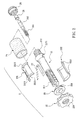
- FIG. 1 is a schematic sectional view of a conventional connecting assembly having a removable fastening mechanism connectable to a socket of a cigar lighter of an automobile;
- FIG. 2 is an exploded view of a removable fastening mechanism according to the invention
- FIG. 3 is a perspective view of the assembled removable fastening mechanism shown in FIG. 2 ;
- FIG. 4 is a schematic sectional view of the removable fastening mechanism of FIG. 2 connected to a seat and a power cord via an arm.
- the removable fastening mechanism 2 connectable to a socket of a cigar lighter of an automobile in accordance with the invention.
- the removable fastening mechanism 2 comprises a hollow shank 21 , a rotatable ring 22 , two curved plates 231 and 232 , and a flexible sleeve 24 which is formed of rubber being adapted to appropriately deform and return to the same once a force exerted thereon is removed.
- External threads 211 are formed on an outer surface of the hollow shank 21 at one end and a conical member 212 is formed around the hollow shank 21 proximate the other end.
- Internal threads 221 are formed in the bore of the rotatable ring 22 .
- the internal threads 221 may be driven onto the external threads 211 so that the rotatable ring 22 may be threadedly moved along the length of the external threads 211 back and forth.
- the flexible sleeve 24 is put on the curved plates 231 and 232 for urging the curved plates 231 and 232 on the hollow shank 21 from two opposite directions.
- the curved plates 231 and 232 are disposed between the rotatable ring 22 and the conical member 212 .
- a driver may first insert the removable fastening mechanism 2 into the socket of cigar lighter of car. Next, rotate the rotatable ring 22 for pushing it toward the socket of the cigar lighter. Further, the curved plates 231 and 232 are gradually pushed toward the surface of the conical member 212 by the rotatable ring 22 . The diameter of the removable fastening mechanism 2 will increase gradually since the surface of the conical member 212 is inclined. Eventually, the removable fastening mechanism 2 stuffs inside of the socket of the cigar lighter. As a result, the removable fastening mechanism 2 is fastened in the socket of the cigar lighter. To the contrary a driver may turn and loosen the rotatable ring 22 for moving it away from the socket of the cigar lighter.
- the curved plates 231 and 232 may return to their original positions with respect to the hollow shank 21 by the elastic expansion of the flexible sleeve 24 .
- the diameter of the removable fastening mechanism 2 returns to its original length, resulting in a loosening of the removable fastening mechanism 2 from the socket of the cigar lighter.
- the driver can remove the removable fastening mechanism 2 from the socket of the cigar lighter.
- the removable fastening mechanism 2 may further comprises a moveable conical member 25 on the hollow shank 21 between the rotatable ring 22 and the conical member 212 (see FIG. 2 ).
- the inclined surface of the moveable conical member 25 is opposite that of the conical member 212 .
- the flexible sleeve 24 and the curved plates 231 and 232 are disposed between the moveable conical member 25 and the conical member 212 .
- a driver may first insert the removable fastening mechanism 2 into the socket of cigar lighter. Next, rotate the rotatable ring 22 for pushing it toward the socket of the cigar lighter. Further, the moveable conical member 25 are gradually pushed toward and inserted in one ends of the curved plates 231 and 232 by the rotatable ring 22 . Furthermore, the conical member 212 is inserted in the other ends of the curved plates 231 and 232 . As such, the diameters of the removable fastening mechanism 2 at both ends will increase. As a result, the curved plates 231 and 232 are securely fastened in the socket of the cigar lighter with the flexible sleeve 24 being compressed against the interior wall of the socket of the cigar lighter.
- the removable fastening mechanism 2 further comprises a hollow arm 3 having one end coupled to one end of the hollow shank 21 and the other end coupled to a seat 4 with an electronic device (e.g., a PDA having the feature of GPS, a mobile phone, or an LCD TV) mounted thereon.
- an electronic device e.g., a PDA having the feature of GPS, a mobile phone, or an LCD TV
- a first hole is formed at the bore of the hollow shank 21 .
- An opening 2311 is formed on the surface of the curved plate 231 .
- the opening 2311 is in communication with the first hole.
- a conductive piece 27 has one end gripped between the flexible sleeve 24 and the curved plate 231 .
- a plug 51 at one end of a power cord 5 is located outside the hollow shank 21 .
- One terminal 521 at the other end of the power cord 5 is inserted through the first hole into the opening 2311 to couple to the conductive piece 27 .
- the other terminal 522 at the other end of the power cord 5 extends through the first hole to couple to a hollow, cylindrical conductive terminal 28 at the other end of the hollow shank 21 .
- the other end of the hollow shank 21 is at a position proximate the conical member 212 but distal the rotatable ring 22 .
- a sleeve 26 having internal threads may be threadedly coupled to the hollow shank 21 .
- a second hole is formed in the bore of the sleeve 26 . The second hole is in communication with the first hole.
- the conductive terminal 28 may be fastened in the sleeve 26 with one end of the conductive terminal 28 projected from the second hole.
- a third hole is further formed in the bore of the hollow arm 3 .
- the third hole may communicate with the first hole and allow the power cord 5 to extend in the third hole as one end of the hollow arm 3 is coupled to one end of the hollow shank 21 .
- the plug 51 at one end of the power cord 5 may be located outside the other end of the hollow arm 3 .
- the power cord 5 may be electrically coupled to the positive and negative terminals in the socket of the cigar lighter through the conductive terminal 28 and the conductive piece 27 .
- power for activating the electronic device can be fed thereto when the plug 51 is inserted into a power socket of the electronic device.
- two opposite ribs 2121 are formed on the inclined surface of the conical member 212 .
- two opposite ribs 251 are formed on the inclined surface of the moveable conical member 25 .
- the opposite ribs 251 correspond to the opposite ribs 2121 .
- the opposite ribs 2121 , 251 are served as a spacer for separating one curved plate 231 from the other curved plate 232 .
- a turning of the rotatable ring 22 can either bring the curved plates 231 and 232 toward the hollow shank 21 from opposite sides or move the curved plates 231 and 232 away from each other without an undesired rotation around the hollow shank 21 .
- two ends at the bore of the moveable conical member 25 are flat and two ends of the external threads 211 are also flat.
- the moveable conical member 25 can move back and forth along the hollow shank 21 as the moveable conical member 25 is threadedly coupled to the external threads 211 without an undesired rotation around the hollow shank 21 .
- projecting ridges are formed around the outer surface of the rotatable ring 22 .
- a driver may exert force on the rotatable ring 22 for increasing friction for facilitating the rotation of the rotatable ring 22 .
- an arcuate flange 2312 is formed at either end of the curved plate 231 and an arcuate flange 2321 is formed at either end of the other curved plate 232 .
- the flexible sleeve 24 can be disposed between the arcuate flanges 2312 , 2321 at one end and the arcuate flanges 2312 , 2321 at the other end.
- a resilient member e.g., spring
- the conductive terminal 28 can be inserted through the third hole or pressed into the sleeve 26 .
- a fuse 262 may be provided between the resilient member 261 and the conductive terminal 28 for electrical safety in operation.
Landscapes
- Coupling Device And Connection With Printed Circuit (AREA)
Abstract
The present invention is to provide a removable fastening mechanism comprising a hollow shank including external threads on an outer surface at one end and conical means proximate the other end; a rotatable ring including internal threads in a bore enabling the rotatable ring to move back and forth along the length of the external threads; two curved plates inserted into a flexible sleeve for urging on the shank from two opposite directions, the curved plates being disposed between the rotatable ring and the conical means, wherein turning and moving the rotatable ring toward the curved plates will gradually push the curved plates and the flexible sleeve to a diameter firmly fixed to a socket of a cigar lighter of an automobile.
Description
The present invention relates to removable fastening mechanisms and more particularly to a removable fastening mechanism adapted to connect to the socket of a cigar lighter of a motor vehicle with improved characteristics.
GPS (Global Positioning System) has been widely employed in many applications such as AVL (Automatic Vehicle Location) and AVM (Automatic Vehicle Monitoring) mounted in a fire engine, police car, ambulance, hazardous product carrying vehicle, bus, or truck for monitoring and management purposes. GPS can be combined with a navigation system to form an AVLN (Automatic Vehicle Location and Navigation System).
An implementation of the popular AVLN comprises installing a GPS engine, a GPS antenna, an e-map, and a platform (or software) in a car, and displaying the current location of the car and related routes on an LCD (Liquid Crystal Display) or a TFT (Thin Film Transistor) LCD on the instrument board. As such, a driver can choose an optimum route to the destination by referring to the same.
For keeping up with the trend of developing multifunctional electronic products, a PDA (Personal Digital Assistant) having the feature of GPS has been commercially available recently. Scheduler, notebook, and phonebook features of the PDA can be used in an office, home, or an outdoor environment. Moreover, the PDA can be used as GPS based navigation device while driving a car. That is why the PDAs are widely used by many consumers.
Moreover, for safety reasons it is inappropriate to hold a steering wheel with one hand and hold a mobile phone with the other hand while driving. As such, it is typical that a driver couples a mobile phone to a mobile sound system. In a case of an incoming call occurred, a speaker of the sound system will amplify the ringing. Further, an immediate talking between the driver and the calling party can be amplified. Hence, the driver can talk with the calling party without holding the mobile phone with the other hand.
A well known connecting assembly has been developed for facilitating a driver to operate a mobile phone and a PDA, or view an LCD. Such connecting assembly 1 is illustrated in FIG. 1. As shown, the connecting assembly 1 comprises an arm 11, a seat 12 at one end of the arm 11 for securely coupling to and supporting an electronic device (e.g., PDA, mobile phone, or LCD TV) thereon, and a removable fastening mechanism 13 at the other end of the arm 11 for connecting to a socket of a cigar lighter of a car, the removable fastening mechanism 13 comprising a rotatable ring 131, a first conical member 132, a flexible sleeve 133, and a second conical member 134. One end of the rotatable ring 131 is coupled to the arm 11 and a threaded shank 135 is extended from the other end thereof. The threaded shank 135 is driven through the bores of the first conical member 132 and the flexible sleeve 133 into a threaded bore of the second conical member 134 for fastening.
By configuring as above, in use a driver may first insert the removable fastening mechanism 13 into the socket of cigar lighter of car. Next, rotate the rotatable ring 131 for driving the threaded shank 135 into the bore of the second conical member 134 and thus pushing the first conical member 132 toward the second conical member 134. This in turn shortens the distance between the first conical member 132 and the second conical member 134 gradually. Further, conical surfaces at both sides of the flexible sleeve 133 are pressed toward each other by the first conical member 132 and the second conical member 134. As such, the length of the flexible sleeve 133 is shortened and the diameter thereof is increased. Finally, inside of the socket of the cigar lighter is filled by the flexible sleeve 133. This can achieve the purpose of fastening the connecting assembly 1 in the socket of the cigar lighter. Therefore, using the electronic device mounted on the seat 12 by the driver can be facilitated.
However, a turning of the rotatable ring 131 will also turn both the arm 11 and the seat 12 since the rotatable ring 131 is securely coupled to the arm 11. Hence, the seat 12, in often times, cannot be rotated to an optimum position when the diameter of the flexible sleeve 133 is increased to stuff itself in the socket of the cigar lighter. This may in turn cause inconvenience in operating the electronic device. Two techniques have been proposed to adjust the seat 12 to an optimum position as detailed below.
The first technique requires a driver to turn the rotatable ring 131 until the seat 12 has reached an optimum operating angle or position. However, in often times, it may compress the flexible sleeve 133 excessively, resulting in an elastic fatigue or even crack of the flexible sleeve 133. Alternatively, it is possible that a driver cannot rotate and unfasten the rotatable ring 131 if the socket of the cigar lighter is overstuffed by the removable fastening mechanism 13, resulting in a failure of removing the connecting assembly 1 from the socket of the cigar lighter.
The second technique requires a driver to slightly turn the rotatable ring 131 until it is loosened. Next, adjust the seat 12 to an optimum operating angle or position. However, it may vibrate the connecting assembly 1 while driving on a rough road since the removable fastening mechanism 13 is not secured to the socket of the cigar lighter. As a result, an easy operation of the electronic device mounted on the seat 12 is even impossible.
Thus, it is desirable among users to provide a novel removable fastening mechanism 13 which once connected to the socket of the cigar lighter, a turning of the rotatable ring 131 will not turn the arm 11 either. As a result, it is easy to adjust the seat 12 to an optimum position, thereby enabling a driver to easily operate an electronic device mounted on the seat 12.
An object of the present invention is to provide a removable fastening mechanism connectable to a socket of a cigar lighter of an automobile wherein a seat coupled to one end of the removable fastening mechanism can be adjusted to an optimum operating angle or position for facilitating a driver to operate an electronic device mounted on the seat.
The above and other objects, features and advantages of the present invention will become apparent from the following detailed description taken with the accompanying drawings.
Referring to FIG. 2 , there is shown a removable fastening mechanism 2 connectable to a socket of a cigar lighter of an automobile in accordance with the invention. The removable fastening mechanism 2 comprises a hollow shank 21, a rotatable ring 22, two curved plates 231 and 232, and a flexible sleeve 24 which is formed of rubber being adapted to appropriately deform and return to the same once a force exerted thereon is removed. External threads 211 are formed on an outer surface of the hollow shank 21 at one end and a conical member 212 is formed around the hollow shank 21 proximate the other end. Internal threads 221 are formed in the bore of the rotatable ring 22. The internal threads 221 may be driven onto the external threads 211 so that the rotatable ring 22 may be threadedly moved along the length of the external threads 211 back and forth. Referring to FIG. 3 , the flexible sleeve 24 is put on the curved plates 231 and 232 for urging the curved plates 231 and 232 on the hollow shank 21 from two opposite directions. The curved plates 231 and 232 are disposed between the rotatable ring 22 and the conical member 212.
By configuring as above, in use a driver may first insert the removable fastening mechanism 2 into the socket of cigar lighter of car. Next, rotate the rotatable ring 22 for pushing it toward the socket of the cigar lighter. Further, the curved plates 231 and 232 are gradually pushed toward the surface of the conical member 212 by the rotatable ring 22. The diameter of the removable fastening mechanism 2 will increase gradually since the surface of the conical member 212 is inclined. Eventually, the removable fastening mechanism 2 stuffs inside of the socket of the cigar lighter. As a result, the removable fastening mechanism 2 is fastened in the socket of the cigar lighter. To the contrary a driver may turn and loosen the rotatable ring 22 for moving it away from the socket of the cigar lighter. At the same time, the curved plates 231 and 232 may return to their original positions with respect to the hollow shank 21 by the elastic expansion of the flexible sleeve 24. Finally, the diameter of the removable fastening mechanism 2 returns to its original length, resulting in a loosening of the removable fastening mechanism 2 from the socket of the cigar lighter. At the moment, the driver can remove the removable fastening mechanism 2 from the socket of the cigar lighter.
As stated above, the curved plates 231 and 232 are pushed toward the inclined surface of the conical member 212 as the rotatable ring 22 rotates. Also, the diameter of the removable fastening mechanism 2 increases until it is fastened in the socket of the cigar lighter. For further enhancing the fastening of the removable fastening mechanism 2 in the socket of the cigar lighter, the removable fastening mechanism 2 may further comprises a moveable conical member 25 on the hollow shank 21 between the rotatable ring 22 and the conical member 212 (see FIG. 2). The inclined surface of the moveable conical member 25 is opposite that of the conical member 212. Also, the flexible sleeve 24 and the curved plates 231 and 232 are disposed between the moveable conical member 25 and the conical member 212. By configuring as above, in use a driver may first insert the removable fastening mechanism 2 into the socket of cigar lighter. Next, rotate the rotatable ring 22 for pushing it toward the socket of the cigar lighter. Further, the moveable conical member 25 are gradually pushed toward and inserted in one ends of the curved plates 231 and 232 by the rotatable ring 22. Furthermore, the conical member 212 is inserted in the other ends of the curved plates 231 and 232. As such, the diameters of the removable fastening mechanism 2 at both ends will increase. As a result, the curved plates 231 and 232 are securely fastened in the socket of the cigar lighter with the flexible sleeve 24 being compressed against the interior wall of the socket of the cigar lighter.
Referring to FIG. 4 , in the invention the removable fastening mechanism 2 further comprises a hollow arm 3 having one end coupled to one end of the hollow shank 21 and the other end coupled to a seat 4 with an electronic device (e.g., a PDA having the feature of GPS, a mobile phone, or an LCD TV) mounted thereon.
Referring to FIGS. 2 and 4 , in the invention a first hole is formed at the bore of the hollow shank 21. An opening 2311 is formed on the surface of the curved plate 231. The opening 2311 is in communication with the first hole. Also, a conductive piece 27 has one end gripped between the flexible sleeve 24 and the curved plate 231. A plug 51 at one end of a power cord 5 is located outside the hollow shank 21. One terminal 521 at the other end of the power cord 5 is inserted through the first hole into the opening 2311 to couple to the conductive piece 27. The other terminal 522 at the other end of the power cord 5 extends through the first hole to couple to a hollow, cylindrical conductive terminal 28 at the other end of the hollow shank 21.
Referring to FIGS. 2 and 4 again, in the invention the other end of the hollow shank 21 is at a position proximate the conical member 212 but distal the rotatable ring 22. As such, a sleeve 26 having internal threads may be threadedly coupled to the hollow shank 21. A second hole is formed in the bore of the sleeve 26. The second hole is in communication with the first hole. As such, the conductive terminal 28 may be fastened in the sleeve 26 with one end of the conductive terminal 28 projected from the second hole.
Referring to FIGS. 2 and 4 again, a third hole is further formed in the bore of the hollow arm 3. The third hole may communicate with the first hole and allow the power cord 5 to extend in the third hole as one end of the hollow arm 3 is coupled to one end of the hollow shank 21. Hence, the plug 51 at one end of the power cord 5 may be located outside the other end of the hollow arm 3. By configuring as above, in a case of the removable fastening mechanism 2 mounted in the socket of the cigar lighter, the power cord 5 may be electrically coupled to the positive and negative terminals in the socket of the cigar lighter through the conductive terminal 28 and the conductive piece 27. Thus, power for activating the electronic device can be fed thereto when the plug 51 is inserted into a power socket of the electronic device.
Referring to FIGS. 2 and 3 , means for preventing the curved plates 231 and 232 from undesirably rotating around the hollow shank 21 is provided by the invention. In detail, two opposite ribs 2121 are formed on the inclined surface of the conical member 212. Also, two opposite ribs 251 are formed on the inclined surface of the moveable conical member 25. The opposite ribs 251 correspond to the opposite ribs 2121. By configuring as above, the opposite ribs 2121, 251 are served as a spacer for separating one curved plate 231 from the other curved plate 232. Hence, a turning of the rotatable ring 22 can either bring the curved plates 231 and 232 toward the hollow shank 21 from opposite sides or move the curved plates 231 and 232 away from each other without an undesired rotation around the hollow shank 21. Moreover, two ends at the bore of the moveable conical member 25 are flat and two ends of the external threads 211 are also flat. As an end, the moveable conical member 25 can move back and forth along the hollow shank 21 as the moveable conical member 25 is threadedly coupled to the external threads 211 without an undesired rotation around the hollow shank 21.
Referring to FIG. 2 , in the invention projecting ridges are formed around the outer surface of the rotatable ring 22. Hence, in use a driver may exert force on the rotatable ring 22 for increasing friction for facilitating the rotation of the rotatable ring 22. Also, an arcuate flange 2312 is formed at either end of the curved plate 231 and an arcuate flange 2321 is formed at either end of the other curved plate 232. By configuring as above, the flexible sleeve 24 can be disposed between the arcuate flanges 2312, 2321 at one end and the arcuate flanges 2312, 2321 at the other end.
Referring to FIG. 2 again, a resilient member (e.g., spring) 261 can be provided in the second hole. As such, the conductive terminal 28 can be inserted through the third hole or pressed into the sleeve 26. Moreover, a fuse 262 may be provided between the resilient member 261 and the conductive terminal 28 for electrical safety in operation.
While the invention has been described by means of specific embodiments, numerous modifications and variations could be made thereto by those skilled in the art without departing from the scope and spirit of the invention set forth in the claims.
Claims (10)
1. A removable fastening mechanism for connecting to a socket of a cigar lighter of a motor vehicle, comprising:
a hollow shank including external threads on an outer surface at one end and conical means proximate the other end;
a rotatable ring including internal threads in a bore, the internal threads being threadedly coupled onto the external threads so that the rotatable ring is operative to move back and forth along the length of the external threads;
a flexible sleeve; and
two curved plates inserted into the flexible sleeve for urging on the shank from two opposite directions, the curved plates being disposed between the rotatable ring and the conical means,
wherein turning and moving the rotatable ring toward the curved plates will gradually push the curved plates to an inclined surface of the conical means for gradually increasing a diameter of the flexible sleeve put on the curved plates.
2. The removable fastening mechanism of claim 1 , further comprising a moveable conical member on the shank between the rotatable ring and the conical means, and wherein an inclined surface of the moveable conical member is opposite that of the conical means and the curved plates and the flexible sleeve put on the curved plates are disposed between the moveable conical member and the conical means.
3. The removable fastening mechanism of claim 2 , further comprising
a hollow arm, the hollow arm having one end coupled to one end of the shank and a seat at the other end of the arm for mounting an electronic device thereon;
a first hole at a bore of the shank;
an opening on a surface of one curved plate, the opening being in communication with the first hole, a conductive piece having one end gripped between the flexible sleeve and one curved plate, a power cord having an end plug located outside the shank, a first terminal at the other end inserted through the first hole into the opening to couple to the conductive piece, and a second terminal at the other end, and a hollow, cylindrical conductive terminal at the other end of the shank, and wherein the second terminal is extended through the first hole to couple to the hollow, cylindrical conductive terminal.
4. The removable fastening mechanism of claim 3 , further comprising a sleeve member having internal threads, the sleeve member being threadedly coupled to the shank, and wherein the sleeve member includes a second hole in a bore in communication with the first hole so that the conductive terminal is adapted to fasten in the sleeve member and one end of the conductive terminal is projected from the second hole.
5. The removable fastening mechanism of claim 4 , further comprising a third hole in a bore of the arm, and wherein the third hole is in communicate with the first hole, the power cord is extended in the third hole, and the plug at one end of the power cord is located outside the other end of the arm in response to coupling one end of the arm to one end of the shank.
6. The removable fastening mechanism of claim 5 , further comprising a resilient member between the second terminal of the power cord and the conductive terminal, the resilient member being operative to push the conductive terminal through the third hole or into the sleeve member.
7. The removable fastening mechanism of claim 6 , further comprising a fuse between the resilient member and the conductive terminal.
8. The removable fastening mechanism of claim 7 , further comprising two opposite first ribs on the inclined surface of the conical means and two opposite second ribs on the inclined surface of the moveable conical member, wherein the first ribs correspond the second ribs, and the first and the second ribs are disposed to separate one curved plate from the other curved plate for disabling a turning of the curved plates around the shank.
9. The removable fastening mechanism of claim 2 , wherein two ends at a bore of the moveable conical member are flat and two ends of the external threads are flat so that the moveable conical member is operative to move back and forth along the shank in response to threadedly coupling the moveable conical member to the external threads, and a turning of the moveable conical member around the shank is disabled.
10. The removable fastening mechanism of claim 2 , further comprising a first arcuate flange at either end of one curved plate and a second arcuate flange at either end of the other curved plate, wherein the flexible sleeve is adapted to dispose between the first and the second flanges at one end and the first and the second flanges at the other end.
Priority Applications (1)
| Application Number | Priority Date | Filing Date | Title |
|---|---|---|---|
| US10/671,800 US6902437B1 (en) | 2003-09-29 | 2003-09-29 | Removable fastening mechanism connectable to socket of cigar lighter of automobile |
Applications Claiming Priority (1)
| Application Number | Priority Date | Filing Date | Title |
|---|---|---|---|
| US10/671,800 US6902437B1 (en) | 2003-09-29 | 2003-09-29 | Removable fastening mechanism connectable to socket of cigar lighter of automobile |
Publications (1)
| Publication Number | Publication Date |
|---|---|
| US6902437B1 true US6902437B1 (en) | 2005-06-07 |
Family
ID=34619753
Family Applications (1)
| Application Number | Title | Priority Date | Filing Date |
|---|---|---|---|
| US10/671,800 Expired - Fee Related US6902437B1 (en) | 2003-09-29 | 2003-09-29 | Removable fastening mechanism connectable to socket of cigar lighter of automobile |
Country Status (1)
| Country | Link |
|---|---|
| US (1) | US6902437B1 (en) |
Cited By (7)
| Publication number | Priority date | Publication date | Assignee | Title |
|---|---|---|---|---|
| US20060030202A1 (en) * | 2004-08-04 | 2006-02-09 | Joachim Bury | Electrical connecting and fastening apparatus |
| US7040932B1 (en) * | 2005-06-14 | 2006-05-09 | Orrin Edward Klitzner | Collapsible plug |
| US7500881B1 (en) * | 2007-12-18 | 2009-03-10 | Sonnenschein Industry Co., Ltd. | Adapter for an automobile socket |
| US20090269979A1 (en) * | 2006-12-08 | 2009-10-29 | Noah Montena | Cable connector expanding contact |
| US20110254500A1 (en) * | 2010-04-19 | 2011-10-20 | Powertech Industrial Co., Ltd. | Car charger |
| US9273496B2 (en) * | 2011-05-26 | 2016-03-01 | James Theobald | Anti-theft devices and methods |
| US20180323537A1 (en) * | 2016-01-22 | 2018-11-08 | Yaowu Ma | Secure electrical socket and plug |
Citations (7)
| Publication number | Priority date | Publication date | Assignee | Title |
|---|---|---|---|---|
| US2892990A (en) * | 1953-10-19 | 1959-06-30 | Land Air Inc | Electrical connector |
| US4109988A (en) * | 1977-07-15 | 1978-08-29 | Olson Ernest E | Duplex outlet device |
| US4904200A (en) * | 1987-10-01 | 1990-02-27 | Williams Robert A | Test probe apparatus |
| US5116248A (en) * | 1991-02-08 | 1992-05-26 | Valentine Research, Inc. | Power plug for radar warning detector |
| US5860824A (en) * | 1997-04-14 | 1999-01-19 | Fan; Eagle | Extension device for mounting in automobile cigarette lighter holder |
| US6135798A (en) * | 1997-04-10 | 2000-10-24 | Mitsubishi Corporation | Automotive battery plug |
| US6695648B2 (en) * | 2002-07-05 | 2004-02-24 | Sheng Hsin Liao | Supporting and skidproof structure of car lighter plug |
-
2003
- 2003-09-29 US US10/671,800 patent/US6902437B1/en not_active Expired - Fee Related
Patent Citations (7)
| Publication number | Priority date | Publication date | Assignee | Title |
|---|---|---|---|---|
| US2892990A (en) * | 1953-10-19 | 1959-06-30 | Land Air Inc | Electrical connector |
| US4109988A (en) * | 1977-07-15 | 1978-08-29 | Olson Ernest E | Duplex outlet device |
| US4904200A (en) * | 1987-10-01 | 1990-02-27 | Williams Robert A | Test probe apparatus |
| US5116248A (en) * | 1991-02-08 | 1992-05-26 | Valentine Research, Inc. | Power plug for radar warning detector |
| US6135798A (en) * | 1997-04-10 | 2000-10-24 | Mitsubishi Corporation | Automotive battery plug |
| US5860824A (en) * | 1997-04-14 | 1999-01-19 | Fan; Eagle | Extension device for mounting in automobile cigarette lighter holder |
| US6695648B2 (en) * | 2002-07-05 | 2004-02-24 | Sheng Hsin Liao | Supporting and skidproof structure of car lighter plug |
Cited By (12)
| Publication number | Priority date | Publication date | Assignee | Title |
|---|---|---|---|---|
| US20060030202A1 (en) * | 2004-08-04 | 2006-02-09 | Joachim Bury | Electrical connecting and fastening apparatus |
| US7059891B2 (en) * | 2004-08-04 | 2006-06-13 | Weidmüller Interface GmbH & Co. KG | Electrical connecting and fastening apparatus |
| US7040932B1 (en) * | 2005-06-14 | 2006-05-09 | Orrin Edward Klitzner | Collapsible plug |
| US20090269979A1 (en) * | 2006-12-08 | 2009-10-29 | Noah Montena | Cable connector expanding contact |
| US8172593B2 (en) * | 2006-12-08 | 2012-05-08 | John Mezzalingua Associates, Inc. | Cable connector expanding contact |
| US7500881B1 (en) * | 2007-12-18 | 2009-03-10 | Sonnenschein Industry Co., Ltd. | Adapter for an automobile socket |
| US20110254500A1 (en) * | 2010-04-19 | 2011-10-20 | Powertech Industrial Co., Ltd. | Car charger |
| US8512054B2 (en) * | 2010-04-19 | 2013-08-20 | Powertech Industrial Co., Ltd. | Automotive battery plug with retractable conduction sections |
| US9273496B2 (en) * | 2011-05-26 | 2016-03-01 | James Theobald | Anti-theft devices and methods |
| US20180323537A1 (en) * | 2016-01-22 | 2018-11-08 | Yaowu Ma | Secure electrical socket and plug |
| US10797436B2 (en) * | 2016-01-22 | 2020-10-06 | Yaowu Ma | Electrical connector structure adapted for a cigarette lighting device in vehicles |
| US11056828B2 (en) * | 2016-01-22 | 2021-07-06 | Yaowu Ma | Electrical connector structure adapted for vehicle cigarette lighter device |
Similar Documents
| Publication | Publication Date | Title |
|---|---|---|
| US6446923B1 (en) | Apparatus for mounting a mobile device on a support surface | |
| EP1743804B1 (en) | Mount assembly for electronic devices | |
| CN115275724A (en) | Automobile mobile phone connecting device | |
| CN101626668B (en) | Electronic equipment component and fixing device thereof | |
| US6272362B1 (en) | Hand-free handset for use with a cellular telephone in an automobile | |
| US6902437B1 (en) | Removable fastening mechanism connectable to socket of cigar lighter of automobile | |
| JPH1130226A (en) | Folding type portable electronic equipment | |
| CN101244711A (en) | hands-free device | |
| CN2256614Y (en) | Multifunctional hand-free mobile telephone adapter | |
| CA2772870A1 (en) | Compact wireless microphone | |
| CN204614831U (en) | The housing of portable electron device and there is the mobile unit of this housing | |
| US6798892B2 (en) | Rotatable removeable speaker assembly | |
| US20070249412A1 (en) | Handset holder for a vehicle | |
| EP0659318B1 (en) | A portable mounting device, primarily for electrical equipment | |
| CN1866988A (en) | Cradle for portable communication device | |
| CN214325016U (en) | Vehicle-mounted support | |
| KR200248464Y1 (en) | a supporting table for a hands-free | |
| KR200376788Y1 (en) | A many purposes supporter adhered to cars grass | |
| KR200253382Y1 (en) | Portable phone for using hand-free apparatus | |
| JP7285585B2 (en) | Drive recorder body and equipment | |
| CN1605499A (en) | Tightening/loosening structure that can be plugged into the car cigarette lighter socket | |
| JP3098189U (en) | Versatile car screen | |
| CN219673704U (en) | Quick-release structure, shell assembly and bracket device | |
| KR200231076Y1 (en) | Apparatus for Conversion Direction of Hands Free for Cellulra Phone | |
| JP2002205603A (en) | Dashboard with device for installing new model car navigation system |
Legal Events
| Date | Code | Title | Description |
|---|---|---|---|
| REMI | Maintenance fee reminder mailed | ||
| LAPS | Lapse for failure to pay maintenance fees | ||
| STCH | Information on status: patent discontinuation |
Free format text: PATENT EXPIRED DUE TO NONPAYMENT OF MAINTENANCE FEES UNDER 37 CFR 1.362 |
|
| FP | Lapsed due to failure to pay maintenance fee |
Effective date: 20090607 |