US6901421B2 - System, method and computer program product for signal processing of array data - Google Patents
System, method and computer program product for signal processing of array data Download PDFInfo
- Publication number
- US6901421B2 US6901421B2 US10/105,847 US10584702A US6901421B2 US 6901421 B2 US6901421 B2 US 6901421B2 US 10584702 A US10584702 A US 10584702A US 6901421 B2 US6901421 B2 US 6901421B2
- Authority
- US
- United States
- Prior art keywords
- data
- receiver
- group
- vectorized
- sub
- Prior art date
- Legal status (The legal status is an assumption and is not a legal conclusion. Google has not performed a legal analysis and makes no representation as to the accuracy of the status listed.)
- Expired - Lifetime, expires
Links
- 238000012545 processing Methods 0.000 title claims abstract description 148
- 238000000034 method Methods 0.000 title claims description 53
- 238000004590 computer program Methods 0.000 title claims description 36
- 230000004044 response Effects 0.000 claims abstract description 96
- 230000003750 conditioning effect Effects 0.000 claims abstract description 68
- 239000011159 matrix material Substances 0.000 claims description 57
- 238000002156 mixing Methods 0.000 claims description 34
- 238000005070 sampling Methods 0.000 claims description 26
- 238000001914 filtration Methods 0.000 claims description 5
- 238000003860 storage Methods 0.000 claims description 5
- 230000008569 process Effects 0.000 description 23
- 230000015654 memory Effects 0.000 description 17
- 239000000523 sample Substances 0.000 description 16
- 238000010586 diagram Methods 0.000 description 11
- 230000006870 function Effects 0.000 description 11
- XLYOFNOQVPJJNP-UHFFFAOYSA-N water Substances O XLYOFNOQVPJJNP-UHFFFAOYSA-N 0.000 description 8
- 238000004458 analytical method Methods 0.000 description 7
- 230000008901 benefit Effects 0.000 description 7
- 238000002360 preparation method Methods 0.000 description 5
- 238000001228 spectrum Methods 0.000 description 5
- 238000003491 array Methods 0.000 description 4
- 230000000712 assembly Effects 0.000 description 4
- 238000000429 assembly Methods 0.000 description 4
- 230000001427 coherent effect Effects 0.000 description 3
- 230000001143 conditioned effect Effects 0.000 description 3
- 238000013500 data storage Methods 0.000 description 2
- 238000012986 modification Methods 0.000 description 2
- 230000004048 modification Effects 0.000 description 2
- 238000002604 ultrasonography Methods 0.000 description 2
- 241000251468 Actinopterygii Species 0.000 description 1
- 241000251729 Elasmobranchii Species 0.000 description 1
- 238000004364 calculation method Methods 0.000 description 1
- 230000003247 decreasing effect Effects 0.000 description 1
- 238000001514 detection method Methods 0.000 description 1
- 238000011161 development Methods 0.000 description 1
- 238000004519 manufacturing process Methods 0.000 description 1
- 238000013507 mapping Methods 0.000 description 1
- 230000000737 periodic effect Effects 0.000 description 1
- 230000000135 prohibitive effect Effects 0.000 description 1
- 238000011160 research Methods 0.000 description 1
- 239000013049 sediment Substances 0.000 description 1
Images
Classifications
-
- G—PHYSICS
- G06—COMPUTING; CALCULATING OR COUNTING
- G06F—ELECTRIC DIGITAL DATA PROCESSING
- G06F17/00—Digital computing or data processing equipment or methods, specially adapted for specific functions
- G06F17/10—Complex mathematical operations
- G06F17/15—Correlation function computation including computation of convolution operations
Definitions
- the present invention relates generally to arrays of sensors such as hydrophones and, more particularly, to systems and methods for signal processing of array data produced by sensors.
- sensors are used to receive information for processing and/or analysis by the system.
- active sonar systems project a beam-like sound wave signal into the water, and an object that is in the path of the signal reflects a portion of the signal back to sensors, such as hydrophones.
- the signal reflected back to the sonar is detected by the sensors and thereafter utilized by the sonar to locate the object in the water.
- One conventional sonar system includes a projector that projects a sound wave signal s(t) into the water. Portions of the signal projected from the projector are reflected from the object to a lower receiver and an upper receiver in the form of an echo signal.
- the sonar system can determine various attributes of the object, such as a vertical arrival angle that partially defines the position of the object with respect to the sonar system.
- many of these modern data processing systems include one or more arrays of many sensors, or receiver elements, such as eighty-eight receiver elements, with each of the receiver elements requiring its own analog conditioning electronics and analog-to-digital converter. Further, digital signal processing is typically required for the receiver elements.
- data from the array of sensors are received by the system in such a manner that all elements from a single time sample are grouped together. But to process the data, most conventional systems require the data to first be organized by each element across all time samples. As such, the data must be reordered, “corner turned” or transposed, before the system can process the data.
- the digital signal processing or portions thereof is performed by hardware circuitry, or special purpose software running on arrays of digital signal processing devices.
- hardware and special purpose software adequately perform the digital signal processing required, each method has drawbacks.
- conventional sonar systems are often deployed on watercraft, such as unmanned undersea vehicles, and in some cases the resources associated with the watercraft, such as space, power, weight and processing capability, are limited.
- the inclusion of the digital processing circuitry can be prohibitive.
- digital processing special purpose software the need to corner turn the data, which is memory input/output (I/O) intensive, slows down the digital processing because no computations are performed during corner turning. That is, data are simply moved from one location to another in preparation for processing at a next stage.
- I/O memory input/output
- the present invention provides an improved system, method and computer program product for processing digital data from an array of i receiving elements.
- the system, method and computer program product do not require the hardware circuitry that can put undesirable burdens on the space, power, weight and processing capability of a sonar system within which it is employed.
- the system, method and computer program product are capable of processing the digital data without corner turning the data in preparation for subsequent processing. As such, the system, method and computer program product of the present invention does not suffer from the undesirable slow down caused by corner turning, when no computations are performed during corner turning.
- a system for processing digital data from an array of i receiving elements, where the digital data comprises t time samples of receiver data for each receiving element.
- the system includes an input assembly interface, a processing element, and can include a beamformer and a matched filter.
- the input assembly interface is capable of providing the digital data from the array of receiving elements, where the digital data comprises receiver data, x(n), and where the receiver data x(n) comprises receiver data x i (n) for each receiving element in the array, where n represents each time sample.
- the array of receiving elements can include at least one subset, j, of a predetermined number, E, of receiving elements.
- the input assembly interface is capable of providing the digital data from the subset(s).
- the predetermined number of receiving elements E in the subset(s) equals a predefined number of bits simultaneously processed by the processing element divided by a number of bits included in each time sample of receiver data.
- the processing element is capable of providing an impulse response vector h(w) including l coefficients corresponding to a length l low pass filter, where w represents each coefficient.
- the processing element is capable of representing the receiver data x(n) as a plurality of vectorized data matrices vx, and the impulse response vector h(w) as a plurality of vectorized response matrices vh.
- the receiver data for each receiving element x i (n) and the impulse response vector h(w) each comprises at least respective sub-group, k.
- each sub-group of receiver data for each receiving element includes a plurality of time samples and each sub-group of the impulse response vector includes a plurality of coefficients, where each time sample for each receiving element and each coefficient of the impulse response vector belongs to a single sub-group of receiver data and response data, respectively.
- Each sub-group, k, of receiver data and each sub-group, k, of the impulse response vector can include a plurality of time samples and coefficients, respectively, separated from one another by a decimation integer, d, such that each sub-group of receiver data includes t/d time samples and each sub-group of the impulse response vector includes l/d coefficients.
- the processing element is capable of representing the receiver data from the receiving elements as an array of vectorized data matrices including a vectorized data matrix, vx jk , for each sub-group of each subset of receiving elements.
- the processing element is also capable of representing the impulse response vector as an array of vectorized response matrices including a vectorized response matrix, vh k , for each sub-group of the impulse response vector.
- the processing element is further capable of converting the vectorized data matrix for each sub-group of each subset of receiving elements into at least one floating point vectorized data matrix, vf jk .
- the processing element can convert the vectorized data matrix for each sub-group of each subset of receiving elements into p floating point vectorized data matrices vf jk1 through vf jkp , where p equals E/F, E equals a predetermined number of receiving elements in at least one subset of the receiving elements, and F equals a predefined number of bits simultaneously processed by the processing element divided by a number of floating point bits.
- the processing element is capable of signal conditioning the receiver data to thereby determine a signal conditioning output.
- the processing element can signal condition the receiver data including decimating the low pass filter response according to the decimation integer, d, that equals a power of two.
- the processing element is capable of signal conditioning the receiver data based upon a relationship between the sampling frequency f s and the mixing frequency f m .
- the beamformer is capable of beamforming the signal conditioning output.
- the matched filter is capable of matched filtering the beamformed signal conditioning output.
- the present invention provides a method and computer program product for processing digital data from an array of i receiving elements.
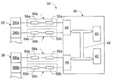
- FIG. 1 is a block diagram illustrating portions of a sonar system that would benefit from one embodiment of the present invention
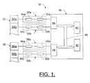
- FIG. 2 is a block diagram of an input data interface element of the sonar system depicted in FIG. 1 according to one embodiment of the present invention.
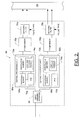
- FIG. 3 diagrammatically illustrates the sonar system of one embodiment of the present invention being used to locate an object in a body of water.
- FIG. 1 one type of active sonar system 30 that would benefit from the real-time signal processing afforded by the present invention is depicted. It should be understood, however, that the active sonar system illustrated and hereinafter described is merely illustrative of one type of system that would benefit from the present invention and, therefore, should not be taken to limit the scope of the present invention. While several embodiments of the system are illustrated and will be hereinafter described for purposes of example, other types of systems can readily employ the real-time signal processing afforded by the present invention. Moreover, the system, method and computer program product of the present invention will be primarily described in conjunction with marine and submarine applications.
- system, method and computer program product of the present invention can be utilized in conjunction with a variety of other applications, both in the marine and submarine industries and outside of those industries.
- system, method and computer program product can be utilized in conjunction with passive sonar systems, as well as radar systems, communications systems and ultrasound instrumentation systems.
- the active sonar system 30 includes a projector assembly 32 in the form of a one-dimensional array of N projector elements 34 , two of which are illustrated in FIG. 1 and identified as projector element 34 a and 34 b .
- a projector array is a projector array of an STA-020-0 Forward Looking Sonar, which is available from Sonatech, Inc. of Santa Barbara, Calif.
- the projector elements which are preferably transducers, are conventional and should be understood by those skilled in the art.
- the projector elements are preferably vertically arranged and contiguous.
- Each of the projector elements projects one or more signals, which are most preferably sound waves that are projected into water. A reflected portion of the signals is received by a receiver assembly 36 of the sonar system, as described below.
- the sonar system 30 further includes a computer-like device 38 .
- a computer is shown in FIG. 1 , the computer may be replaced with any device suitable for facilitating the operations of the present invention.
- the computer includes a processor 40 and a memory 42 .
- the memory can include one or more read-only memories, random access memories, and data storage devices.
- the data storage devices may be in the form of one or more hard disks and drives therefor, floppy disks and drives therefor, CD-ROMs and drives therefor, digital video disks and drives therefor, memory cards, or the like.
- the computer further includes an output data interface 44 and an input data interface element 46 , and user interface components (not shown). The components of the computer are operatively interconnected by a bus 48 .
- a separate output electronics assembly 50 extends between the output data interface 44 and each of the projector elements 34 a and 34 b .
- Each output electronics assembly includes a digital-to-analog converter 52 and analog conditioning electronics 54 that are designed to drive the respective projector elements as directed by the computer 38 .
- the output electronics assemblies are conventional and should be understood by those skilled in the art.
- the receiver assembly 36 consists of an array of A receiver elements 56 , only two of which are illustrated in FIG. 1 and identified as receiver elements 56 a and 56 b .
- receiver elements 56 a and 56 b there may be eighty-eight receiver elements 56 , with each capable of providing analog data.
- the receiver elements 56 which are preferably hydrophones, are conventional and should be understood by those skilled in the art.
- One example of a suitable receiver array is a receiver array of an STA-020-0 Forward Looking Sonar, which is available from Sonatech, Inc.
- a separate input electronics assembly 58 extends between each of the receiver elements 56 and the input data interface element 46 .
- Each input electronics assembly includes analog conditioning electronics 60 and an analog-to-digital converter 62 which, along with the input data interface element, convert the output of the receiver elements into a proper form for analysis by the processor 40 .
- the input data interface element processes the digital output of the analog-to-digital converters into beam data and performs matched filtering to prepare the output of the receiver elements for analysis by the processor 40 .
- the input data interface element includes an input assembly interface 64 to accept the digital data from the analog-to-digital converters 62 a and 62 b .
- the input data interface element includes central processing units 66 that are capable of signal conditioning the digital data by simultaneously mixing the digital output to baseband, low pass filtering and decimating the digital output, as described below.
- the central processing units include processing elements 68 , and associated memory such as random access memory (RAM) 70 , and nonvolatile memory 72 .
- the processing elements can comprise any of a number of different devices, such as personal computers or other high level processors capable of single instruction, multiple data (SIMD) processing that allows the processing element to perform parallel operations on multiple data of the same type.
- the processing elements can comprise MPC7400 or MPC7410 model microprocessors manufactured by Motorola, Inc. of Schaumburg, Ill., Intel Pentium III model processors manufactured by Intel Corporation of Santa Clara, Calif., or any combination thereof.
- the non-volatile memory 72 such as, for example, flash memory, an EEPROM or a disk, is typically used for storing and/or executing computer program products 74 as well as storing various pieces of useful data.
- the RAM 70 is generally used for loading and executing the computer program product.
- the computer program products generally cooperate with respective processing elements 68 to at least partially process the output of the receiver elements 56 in preparation for analysis by the processor 40 . It should be understood, however, that even though the computer program products can process the output of the receiver elements, all or a portion of this processing can, instead, be accomplished through various hardware or firmware configurations without departing from the spirit and scope of the present invention.
- the input data interface element 46 includes beamformers 76 , as well as matched filters 78 .
- the beamformers are spatial filters that can operate on the output of the receiver elements 56 in order to enhance the amplitude of a coherent signal relative to background noise and directional interference.
- the matched filters perform coherent correlation of direct and echo signal energy in order to further improve the signal-to-noise ratio of the desired signal over background noise.
- the ordering of the central processing units 66 , and respective beamformers 76 and matched filters 78 of the illustrated embodiment of the input data interface element 46 represent only one of a number of possible configurations of the input data interface element of the present invention.
- the central processing units, and respective beamformers and matched filters can be placed in any order relative to one another without departing from the spirit and scope of the present invention.
- the central processing units and/or the processor 40 can perform the functions of the beamformers and/or matched filters without departing from the spirit and scope of the present invention.
- the input data interface element would not include separate elements for those respective functions performed by the central processing units and/or the processor.
- the central processing units are illustrated and described as being separate elements within the input data interface element, the processor can be configured to perform the functions of the central processing units such that the input data interface element does not include separate central processing units.
- the computer 38 of the sonar system 30 operates in conjunction with the output electronics assemblies 50 so that a signal s(t) is projected from the projector 32 on a periodic basis.
- a waveform corresponding to the signal s(t) may be stored in the memory 42 .
- the waveform is periodically retrieved from the memory by the processor 40 , which appropriately directs the waveform to the output data interface 44 .
- the signal s(t) occupies a range of frequencies, or bandwidth, B, that is narrow relative to the center, or carrier frequency, f c , of the respective signal.
- the signal may have a signal bandwidth of 5 kHz, with a center frequency on the order of 100 kHz to 500 kHz or more.
- the high center frequency is required in order to achieve the required azimuthal resolution for a given physical sonar length.
- the bandwidth is chosen to provide the desired range resolution.
- Operation of the sonar system 30 may be best understood with reference to FIG. 3 , in which the sonar system is illustrated as being used to locate an object 84 suspended within a body of water 86 .
- the projector 80 transmits the signal s(t), with a direction of projection arrow 88 illustrating the direction that the signal s(t) travels from the projector to the object.
- the signal s(t) is transmitted periodically for a duration that is less than the period. The period will be varied depending upon the distance to the object. Nonetheless, as one example, a suitable period and duration may be 1.0 second and 0.01 second, respectively.
- a portion of the signal s(t) encounters the object and is reflected back to the receiver assembly 36 of the sonar system as an echo signal 90 .
- the sonar system 30 can utilize the receiver data to determine the distance between the sonar system and the object by determining the time required for an echo of the signal s(t) to return to the sonar system from the object. Determination of the distance between a sonar system and an object is conventional and should be understood by those skilled in the art. As such, the sonar system can precisely locate an object. Before the sonar system can utilize the receiver data, however, the input data interface element 46 must process the receiver data in preparation for analysis by the processor. In this regard, according to one embodiment of the present invention, the analog-to-digital converters 62 convert the analog conditioned receiver data from the analog conditioning electronics 60 into digital receiver data.
- the Nyquist sampling criterion requires that, to properly represent the analog conditioned receiver data, the analog-to-digital converter must sample the data at a frequency that is at least twice that of the highest frequency present in the signal.
- the sampling frequency, f s of the analog-to-digital converters is typically at least 2f c +B.
- the sampling frequency is selected to be four times the center frequency f c .
- the input assembly interface 64 receives the digital data, x(n), from the analog-to-digital converters as an A ⁇ n matrix of receiver data including receiver data x i (n) for each receiver element 56 in the array of A receiver elements (where i equals integers 1 through A).
- the digital data for each receiver element includes t time samples, where n corresponds to each time sample and equals integers 0 through t ⁇ 1. It should be noted that the number of time samples t is selected to be greater than or equal to the length l of a low pass filter applied to the digital data by the processing elements 68 , with the number of time samples generally numbering many times the length of the low pass filter, as described below.
- the input assembly interface 64 passes the digital data to the central processing units 66 .
- the digital receiver data, x i (n) for each time sample, n, of each receiver element 56 , i can be represented as a d by t/d matrix, where d equals a decimation integer and t equals the number of time samples.
- the digital receiver data for each receiver element can be grouped into at least one sub-group, k, where each sub-group includes a plurality of time samples and each time sample for each receiver element belongs to a single sub-group of receiver data.
- each row of the matrix corresponds to one sub-group.
- the time samples in each sub-group are arranged in the order in which the time samples were received from the respective receiver element but spaced apart by the decimation integer d.
- xm i x i ⁇ ( 0 ) x i ⁇ ( 4 ) ⁇ x i ⁇ ( 24 ) x i ⁇ ( 28 ) x i ⁇ ( 1 ) x i ⁇ ( 5 ) ⁇ x i ⁇ ( 25 ) x i ⁇ ( 29 ) x i ⁇ ( 2 ) x i ⁇ ( 6 ) ⁇ x i ⁇ ( 26 ) x i ⁇ ( 30 ) x i ⁇ ( 3 ) x i ⁇ ( 7 ) ⁇ x i ⁇ ( 27 ) x i ⁇ ( 31 ) ⁇ ⁇ ⁇
- the digital data for each receiver element described herein will be described and illustrated in matrix form, the digital data for each receiver element need not be, and are preferably not, organized or processed in matrix form within the sonar system 30 .
- the digital data is preferably processed in the form, x(n), in which analog-to-digital converters 62 provide the digital data to the input data interface element 46 after the data from the receiver elements has passed through the input electronics assembly 58 .
- the number of time samples shown above is greater than or equal to 32, it will be appreciated that the number of time samples will typically include many more than 32, often numbering tens of thousands of time samples.
- the processing elements 68 cooperate with the respective RAM 70 and nonvolatile memory 72 to execute the computer program product 74 to process the digital receiver data to thereby prepare the digital receiver data for analysis by the processor 40 .
- the analog-to-digital converters 62 typically sample the analog conditioned receiver data at a rate of at least 2f c +B. Such a sampling frequency, however, is excessive because the information in the signal only occupies a bandwidth of B. To avoid requiring all digital signal processing to operate at such a high rate, the processing elements 68 mix the digital receiver data to shift the signal band to a much lower frequency, such as 0 Hz.
- f m f s 2 a ( 3 )
- a is any positive integer greater than one, but preferably either 2, 3 or 4, as described below.
- the signal spectrum cannot contain frequencies greater than or equal to half the sampling frequency.
- the sine and cosine factors assume the values of 0 and ⁇ 1 and repeat every four samples. In fact, the patterns repeat every two samples, but with alternating sign.
- the mixing frequency is equal to one-eighth the sampling frequency and the sine and cosine factors repeat every eight samples (or every four samples with alternating sign). And for the case where a is chosen equal to four, the sine and cosine factors repeat every sixteen samples, or every eight samples with alternating sign.
- a typical system will use the technique described in the present invention to signal condition the digital data by simultaneously shifting, i.e., mixing, the input data to a frequency close to 0 Hz, low pass filtering and decimating to a low frequency, as described below.
- subsequent digital processing that operates at the reduced sampling frequency can make further adjustments in center frequency if desired without departing from the spirit and scope of the present invention.
- systems that estimate Doppler frequency may require additional frequency adjustment in the digital domain.
- the processing elements 68 low pass filter the digital receiver data to remove out-of-band energy that would otherwise fold into the signal bandwidth.
- the processing elements can sub-sample the filtered digital receiver data by the decimation integer d to thereby limit the rate of the digital receiver data to be consistent with B Hz, the narrow bandwidth of the signal s(t).
- the processing elements 68 process the digital receiver data according to the bit length of the digital receiver data and the SIMD capabilities of the processing element.
- V the SIMD registers
- each processing element can process the digital data in multiples of 128 bits.
- each processing element then can process the digital receiver data for 8 receiver elements in parallel at one time utilizing the SIMD capabilities of the processing element (i.e., each processing element processes the 16 bits of data of 8 receiver elements for a total of 128 bits).
- each processing element can repeat the processing steps for each successive subset (1, 2, 3, . . . A/E) of the number of receiver elements it can process at one time until the digital receiver data for the entire array of receiver elements has been processed (i.e., E, 2E, 3E, . . . A).
- the processing elements can repeat the processing steps for each subset of eight receiver elements for a total of eleven passes through the processing steps.
- the receiver assembly will generally be selected to include subsets of eight receiver elements. It should be understood, however, that the receiver assembly can include subsets of any number of receiver elements without departing from the spirit and scope of the present invention.
- dummy elements with fictitious data can be processed with the final subset to bring the total number of processed elements (receiver elements plus dummy elements) up to a multiple of the number of receiver elements in each subset.
- a processing element capable of processing digital receiver data for eight receiver elements at one time and a receiver assembly including seventy receiver elements.
- One example of such a receive array is a receive array of an SLS-015-2 Side Looking Sonar, which is available from Sonatech, Inc. of Santa Barbara, Calif.
- each subset would still only consist of eight receiver elements, followed by a final (i.e., ninth) pass through the processing step processing the digital receiver data for the last six receiver elements along with fictitious data for two dummy elements.
- the fictitious data for the dummy elements can be input into the processing element in any one of a number of different manners, such as through analog or digital electronics in the electronics assembly 58 .
- the processing elements 68 cooperate with the respective RAM 70 and nonvolatile memory 72 to execute the computer program product 74 to mix the digital receiver data to a baseband frequency and provide a reasonably low data rate for subsequent processing and/or analysis of the digital receiver data.
- the processing elements can low pass filter the digital receiver data with a length l low pass filter to thereby select the difference frequency component and to attenuate the sum frequency component so as to remove out-of-band energy that would otherwise fold into the signal bandwidth.
- each sub-group of impulse response vector h(w) includes the coefficients of h(w) arranged in the same decreasing order but spaced apart by the decimation integer d.
- hm h ⁇ ( 31 ) h ⁇ ( 27 ) h ⁇ ( 23 ) h ⁇ ( 19 ) h ⁇ ( 15 ) h ⁇ ( 11 ) h ⁇ ( 7 ) h ⁇ ( 3 ) h ⁇ ( 30 ) h ⁇ ( 26 ) h ⁇ ( 22 ) h ⁇ ( 18 ) h ⁇ ( 14 ) h ⁇ ( 10 ) h ⁇ ( 6 ) h ⁇ ( 2 ) h ⁇ ( 29 ) h ⁇ ( 25 ) h ⁇ ( 21 ) h ⁇ ( 17 ) h ⁇ ( 13 ) h ⁇ ( 9 ) h ⁇ ( 5 ) h ⁇ ( 1 ) h ⁇ ( 28 ) h ⁇ ( 24 h ⁇ ( 20 h ⁇ ( 16 ) h
- the processing elements 68 mix and low pass filter the digital receiver data
- the processing elements decimate the digital receiver data by the decimation integer d to thereby decrease the sampling rate to be consistent with the bandwidth of the digital receiver data, such as to B Hz.
- the decimation integer can be any of a number of different integers that are equal to an integer power of two, e.g., 2, 4, 8, 16, etc.
- the processing elements 68 advantageously represent the digital data x(n) received from the analog-to-digital converters 62 as vectorized matrices, or vectorized data matrices, vx jk .
- vectorized matrices vx jk each comprise a corresponding sub-group k of digital receiver data for the receiver elements, x i (n), where j corresponds to each subset of receiver elements (e.g., subsets of eight receiver elements—1, 2, 3 . . . A/E).
- E is the number of receiver elements per subset
- t is the number of time samples per receiver element
- d is the decimation integer.
- vectorized digital receiver data vx lk corresponds to the first subset of receiver elements
- vectorizing refers to adding a dimension to a piece, vector or matrix of data or the like. In this regard, a single point can be vectorized into a 1-dimensional array (or, “vector” hence the term “vectorize”).
- an array is vectorized into a 2-dimensional matrix
- a 2-dimensional matrix is vectorized into a 3-dimenstional structure, often written as “array of matrices” (e.g. vx, vh).
- array of matrices e.g. vx, vh.
- the number of vectorized float matrices can be determined in any number of manners, but preferably equals E/F, where F is the number of floating point elements that can fit within the width, V, of the registers in the processing element that hold the digital receiver data. In other words, F equals V/fp, where fp is the floating point data size.
- the impulse response h(w) is similarly vectorized into an array of matrices, vh k .
- vectorized matrices vh k each comprise a sub-group k of the impulse response vector.
- the decimated output of the low pass filter response can be determined based upon the vectorized float matrices and the vectorized impulse response matrices.
- each row of the vectorized float matrices vf jkg corresponding to a sub-group of digital data for a respective receiver element 56 is simultaneously convolved with the corresponding row of the vectorized impulse response matrix vh k , where the rows of each impulse response matrix vh k correspond to one sub-group of impulse response vector h(w).
- vc jkg vf jkg ⁇ circle around ( ⁇ ) ⁇ vh k , (8) where ⁇ circle around ( ⁇ ) ⁇ represents row-by-row (i.e., sub-group by sub-group) convolution.
- the signal conditioning output can then be determined based upon the relationship between the center frequency f c and the mixing frequency f m , as well as the decimation integer d.
- the signal spectrum cannot contain frequencies greater than or equal to half the sampling frequency.
- vh 1 h ⁇ ( 31 ) - h ⁇ ( 27 ) h ⁇ ( 23 ) - h ⁇ ( 19 ) h ⁇ ( 15 ) - h ⁇ ( 11 ) h ⁇ ( 7 ) - h ⁇ ( 3 ) h ⁇ ( 31 ) - h ⁇ ( 27 ) h ⁇ ( 23 ) - h ⁇ ( 19 ) h ⁇ ( 15 ) - h ⁇ ( 11 ) h ⁇ ( 7 ) - h ⁇ ( 19 ) h ⁇ ( 15 ) - h ⁇ ( 11 ) h ⁇ ( 7 ) - h ⁇ ( 3 ) h ⁇ ( 31 ) - h ⁇ ( 27 ) h ⁇ ( 23 ) - h ⁇ ( 19 ) h ⁇ ( 31 ) - h ⁇ ( 27 ) h ⁇ ( 23 ) - h ⁇ ( 19
- each central processing unit 66 can each include one processing element 68 for calculating both the real and imaginary components of a respective subset of the signal conditioning output
- each central processing unit can include multiple processing elements for calculating the real and imaginary components, or portions thereof, separately.
- one central processing unit can determine the signal conditioning output for multiple subsets of receiver elements.
- the input data interface element 46 need only include one central processing unit, as well as one beamformer 76 and matched filter 78 .
- each central processing unit can process the digital receiver data in an amount of time equal to the time required to process the digital receiver data with one processing element divided by the number of processing elements.
- V 128-bit wide Vector Register
- e 16
- V/e 8
- one processing element 68 of one central processing unit 66 could calculate the real and imaginary components of signal conditioning output for the first subset of eight receiver elements 56 , and the aforementioned steps could be simultaneously performed by the processing element(s) of another central processing unit to determine the signal conditioning output for the second subset of eight receiver elements to thereby complete the signal conditioning output for the entire array of 16 receiver elements simultaneously by two central processing units.
- the processing of real and imaginary components of each subset could be separated and the signal conditioning output can be determined on separate processing elements (not shown).
- the complex output data can pass through the beamformers 76 and the matched filters 78 .
- the beamformers enhance the amplitude of the processed digital receiver data relative to background noise and directional interference to allow the processor 40 to more readily discern the processed digital receiver data relative to the background noise and directional interference.
- the matched filters perform coherent correlations of the pulse type of the transmit signal s(t) in order to further improve the signal-to-noise ratio of the processed digital receiver data over background noise.
- the sonar system 30 is preferably mounted to a watercraft (not shown), such as an unmanned undersea vehicle, in a manner that should be understood by those skilled in the art.
- the projector 32 and receiver 36 may be mounted to the external surface of the hull of the watercraft, whereas the remainder of the sonar system 30 may be carried within the watercraft.
- the sonar system 30 may be for any of the typical applications of sonar, such as: the detection of submarines, torpedoes, water depth, fish, underground pipelines and wrecks; navigation; mapping the ocean floor; determining characteristics of ocean bottom sediments; measuring water current profiles; and the like.
- the digital data is preferably processed according to the entire array of receiver elements in the form in which analog-to-digital converters provide the digital data to the input data interface element after the data from the receiver elements has passed through the input electronics assembly.
- the present invention is capable of processing digital data from an array of receiver elements without requiring the hardware circuitry that can put undesirable burdens on the space, power, weight and processing capability of a sonar system within which it is employed. Also, the present invention is capable of processing the digital data without corner turning the data in preparation for subsequent processing. As such, the present invention does not suffer from the undesirable slow down caused by corner turning, when no computations are performed during corner turning.
- portions of the system and method of the present invention include a computer program product 74 .
- the computer program product includes a computer-readable storage medium, such as the non-volatile storage medium, and computer-readable program code portions, such as a series of computer instructions, embodied in the computer-readable storage medium for receiving the handwritten data and for subsequently processing and transmitting the handwritten data as described hereinabove.
- the computer program is stored by the central processing unit or a related memory device, such as the non-volatile storage device 72 as depicted in FIG. 2 .
- FIGS. 1 and 2 are block diagrams and control flow illustrations of methods, systems and program products according to the invention. It will be understood that each block or step of the block diagram, flowchart and control flow illustrations, and combinations of blocks in the block diagram, flowchart and control flow illustrations, can be implemented by computer program instructions. These computer program instructions may be loaded onto a computer or other programmable apparatus to produce a machine, such that the instructions which execute on the computer or other programmable apparatus create means for implementing the functions specified in the block diagram, flowchart or control flow block(s) or step(s).
- These computer program instructions may also be stored in a computer-readable memory that can direct a computer or other programmable apparatus to function in a particular manner, such that the instructions stored in the computer-readable memory produce an article of manufacture including instruction means which implement the function specified in the block diagram, flowchart or control flow block(s) or step(s).
- the computer program instructions may also be loaded onto a computer or other programmable apparatus to cause a series of operational steps to be performed on the computer or other programmable apparatus to produce a computer implemented process such that the instructions which execute on the computer or other programmable apparatus provide steps for implementing the functions specified in the block diagram, flowchart or control flow block(s) or step(s).
- blocks or steps of the block diagram or control flow illustrations support combinations of means for performing the specified functions, combinations of steps for performing the specified functions and program instruction means for performing the specified functions. It will also be understood that each block or step of the block diagram, flowchart or control flow illustrations, and combinations of blocks or steps in the block diagram, flowchart or control flow illustrations, can be implemented by special purpose hardware-based computer systems which perform the specified functions or steps, or combinations of special purpose hardware and computer instructions.
Abstract
Description
where a is selected from a group consisting of 2, 3 and 4. According to one embodiment, the receiver data for each receiving element xi(n) and the impulse response vector h(w) each comprises at least respective sub-group, k. In this embodiment, each sub-group of receiver data for each receiving element includes a plurality of time samples and each sub-group of the impulse response vector includes a plurality of coefficients, where each time sample for each receiving element and each coefficient of the impulse response vector belongs to a single sub-group of receiver data and response data, respectively. Each sub-group, k, of receiver data and each sub-group, k, of the impulse response vector can include a plurality of time samples and coefficients, respectively, separated from one another by a decimation integer, d, such that each sub-group of receiver data includes t/d time samples and each sub-group of the impulse response vector includes l/d coefficients. As such, the processing element is capable of representing the receiver data from the receiving elements as an array of vectorized data matrices including a vectorized data matrix, vxjk, for each sub-group of each subset of receiving elements.
vc jkg =vf jkg {circle around (×)}vh k,
where {circle around (×)} represents sub-group by sub-group convolution, and where g equals
where yRjg and yIjg equal the real and imaginary parts of the signal conditioning output, respectively. When fs equals 4×fm and the decimation integer d is 2, the processing element signal conditions the receiver data by first multiplying every other coefficient of every sub-group of the vectorized response matrices, vhk, by (−1) and thereafter signal conditioning the receiver data according to the following:
y Rjg(n)=(−1)n vc j1g
y Ijg(n)=(−1)n+1 vc j2g
where n represents each time sample.
And when fs equals 8fm and the decimation integer d is 4, the processing element signal conditions the receiver data by first multiplying every other coefficient of every sub-group of the vectorized response matrices, vhk, by (−1) and thereafter signal conditioning the receiver data according to the following:
In equation (3), a is any positive integer greater than one, but preferably either 2, 3 or 4, as described below. In this regard, it should be noted that for real digital receiver data xi(n), the signal spectrum cannot contain frequencies greater than or equal to half the sampling frequency. As such, the spectrum for real digital receiver data xi(n) for a mixing frequency equal to half the sampling frequency (a=1) cannot be centered at the mixing frequency, so no benefit will be derived from mixing the digital receiver data by fm.
u Il(n)={0,−x l(1),0,x i(3),0,−x i(5),0 . . . }
As shown, the sine and cosine factors (for a=2) assume the values of 0 and ±1 and repeat every four samples. In fact, the patterns repeat every two samples, but with alternating sign. Similarly, for the case where a is chosen to equal three, the mixing frequency is equal to one-eighth the sampling frequency and the sine and cosine factors repeat every eight samples (or every four samples with alternating sign). And for the case where a is chosen equal to four, the sine and cosine factors repeat every sixteen samples, or every eight samples with alternating sign.
In equation (4), just as in the case of representing the receiver data for each receiver element 56, each row of the impulse response matrix corresponds to one sub-group of the impulse response vector h(w). In this regard, as the digital data is preferably decimated by the decimation integer d, each sub-group of impulse response vector h(w) includes the coefficients of h(w) arranged in the same decreasing order but spaced apart by the decimation integer d. For example, for a low pass filter length l=32 and a decimation integer d=4, the first sub-group of h(w) would comprise h(w) for w=31, 27, 23, 19, etc. Then, using the same example, hm including all of the sub-groups could be represented as follows:
In equation (5), E is the number of receiver elements per subset, t is the number of time samples per receiver element and d is the decimation integer. For example, for a first subset of 8 receiver elements 56 (E=8) and a decimation integer of 4, the vectorized digital receiver data vxlk can be represented as follows:
As above, where the decimation integer equals 4 (d=4) and the length of the low pass filter equals 32(l=32), the vectorized low pass filter response can be represented as follows:
Consider now impulse response matrix hm and that each row corresponds to a sub-group of coefficients of the impulse response vector h(w). As seen, then, each row of the impulse response matrix hm is vectorized into vhk, where k indicates the row number of the impulse response matrix hm (e.g., k=1, 2, . . . d).
vc jkg =vf jkg {circle around (×)}vh k, (8)
where {circle around (×)} represents row-by-row (i.e., sub-group by sub-group) convolution. With the convolved rows (sub-groups) from equation (8), the signal conditioning output can then be determined based upon the relationship between the center frequency fc and the mixing frequency fm, as well as the decimation integer d.
After incorporating the alternating signs into vectorized impulse response matrices vhk, the output of signal conditioning can be determined for fs=4×fm, d=2 as follows:
y Rjg(n)=(−1)n vc j1g (11)
y Ijg(n)=(−1)n+1 vc j2g (12)
In equations (13) and (14), q, r, s and w can be determined by equations (15), (16), (17) and (18), respectively, as follows:
And after incorporating the alternating signs into matrices vhk, the signal conditioning output can be determined as follows:
Claims (40)
vc jkg =vf jkg {circle around (×)}vh k,
y Rjg(n)=(−1)n vc j1g
y Ijg(n)=(−1)n+1 vc j2g,
vc jkg =vf jkg {circle around (×)}vh k,
y Rjg(n)=(−1)n vc j1g
y Ijg(n)=(−1)n+1 vc j2g,
vc jkg =vf jkg {circle around (×)}vh k,
y Rjg(n)=(−1)n vc j1g
y Ijg(n)=(−1)n+1 vc j2g,
Priority Applications (1)
| Application Number | Priority Date | Filing Date | Title |
|---|---|---|---|
| US10/105,847 US6901421B2 (en) | 2002-03-25 | 2002-03-25 | System, method and computer program product for signal processing of array data |
Applications Claiming Priority (1)
| Application Number | Priority Date | Filing Date | Title |
|---|---|---|---|
| US10/105,847 US6901421B2 (en) | 2002-03-25 | 2002-03-25 | System, method and computer program product for signal processing of array data |
Publications (2)
| Publication Number | Publication Date |
|---|---|
| US20030182336A1 US20030182336A1 (en) | 2003-09-25 |
| US6901421B2 true US6901421B2 (en) | 2005-05-31 |
Family
ID=28040869
Family Applications (1)
| Application Number | Title | Priority Date | Filing Date |
|---|---|---|---|
| US10/105,847 Expired - Lifetime US6901421B2 (en) | 2002-03-25 | 2002-03-25 | System, method and computer program product for signal processing of array data |
Country Status (1)
| Country | Link |
|---|---|
| US (1) | US6901421B2 (en) |
Cited By (4)
| Publication number | Priority date | Publication date | Assignee | Title |
|---|---|---|---|---|
| US20050187996A1 (en) * | 2004-02-24 | 2005-08-25 | Kun Wah Yip | Multiplierless correlators for HIPERLAN/2 and IEEE 802.11A wireless local area networks |
| US20070266069A1 (en) * | 2003-01-28 | 2007-11-15 | Agere Systems Inc. | Multi-Dimensional Hybrid And Transpose Form Finite Impulse Response Filters |
| CN102073711A (en) * | 2010-12-29 | 2011-05-25 | 中国科学院声学研究所 | Data processing method for sonar data management system |
| US10869108B1 (en) | 2008-09-29 | 2020-12-15 | Calltrol Corporation | Parallel signal processing system and method |
Families Citing this family (5)
| Publication number | Priority date | Publication date | Assignee | Title |
|---|---|---|---|---|
| US7110461B2 (en) * | 2002-07-18 | 2006-09-19 | Sun Microsystems, Inc. | Technique to enlarge data eyes in wireline communication systems |
| US7650285B2 (en) * | 2004-06-25 | 2010-01-19 | Numerex Corporation | Method and system for adjusting digital audio playback sampling rate |
| US7899857B2 (en) * | 2005-12-30 | 2011-03-01 | L3 Communications Corporation | CPU datapipe architecture with crosspoint switch |
| KR20190120363A (en) * | 2017-03-03 | 2019-10-23 | 배 시스템즈 피엘시 | Transceiver |
| EP3370081A1 (en) * | 2017-03-03 | 2018-09-05 | BAE SYSTEMS plc | A digital transceiver |
Citations (10)
| Publication number | Priority date | Publication date | Assignee | Title |
|---|---|---|---|---|
| US4319347A (en) * | 1976-03-08 | 1982-03-09 | Western Geophysical Co. Of America | Seismic method and system of improved resolution and discrimination |
| US4596007A (en) * | 1982-10-12 | 1986-06-17 | Thomson-Csf | Interferometric sonar in non-linear acoustics |
| US5253308A (en) | 1989-06-21 | 1993-10-12 | Amber Engineering, Inc. | Massively parallel digital image data processor using pixel-mapped input/output and relative indexed addressing |
| US5410727A (en) | 1989-10-24 | 1995-04-25 | International Business Machines Corporation | Input/output system for a massively parallel, single instruction, multiple data (SIMD) computer providing for the simultaneous transfer of data between a host computer input/output system and all SIMD memory devices |
| US5655131A (en) | 1992-12-18 | 1997-08-05 | Xerox Corporation | SIMD architecture for connection to host processor's bus |
| US6173388B1 (en) | 1998-04-09 | 2001-01-09 | Teranex Inc. | Directly accessing local memories of array processors for improved real-time corner turning processing |
| US6181643B1 (en) | 1999-07-19 | 2001-01-30 | The Boeing Company | Interferometer with a single projector array and a single receiver array |
| US6275920B1 (en) | 1998-04-09 | 2001-08-14 | Teranex, Inc. | Mesh connected computed |
| US20020171580A1 (en) * | 2000-12-29 | 2002-11-21 | Gaus Richard C. | Adaptive digital beamformer coefficient processor for satellite signal interference reduction |
| US20050009486A1 (en) * | 1999-10-08 | 2005-01-13 | Naofal Al-Dhahir | Finite-length equalization overmulti-input multi-output channels |
-
2002
- 2002-03-25 US US10/105,847 patent/US6901421B2/en not_active Expired - Lifetime
Patent Citations (10)
| Publication number | Priority date | Publication date | Assignee | Title |
|---|---|---|---|---|
| US4319347A (en) * | 1976-03-08 | 1982-03-09 | Western Geophysical Co. Of America | Seismic method and system of improved resolution and discrimination |
| US4596007A (en) * | 1982-10-12 | 1986-06-17 | Thomson-Csf | Interferometric sonar in non-linear acoustics |
| US5253308A (en) | 1989-06-21 | 1993-10-12 | Amber Engineering, Inc. | Massively parallel digital image data processor using pixel-mapped input/output and relative indexed addressing |
| US5410727A (en) | 1989-10-24 | 1995-04-25 | International Business Machines Corporation | Input/output system for a massively parallel, single instruction, multiple data (SIMD) computer providing for the simultaneous transfer of data between a host computer input/output system and all SIMD memory devices |
| US5655131A (en) | 1992-12-18 | 1997-08-05 | Xerox Corporation | SIMD architecture for connection to host processor's bus |
| US6173388B1 (en) | 1998-04-09 | 2001-01-09 | Teranex Inc. | Directly accessing local memories of array processors for improved real-time corner turning processing |
| US6275920B1 (en) | 1998-04-09 | 2001-08-14 | Teranex, Inc. | Mesh connected computed |
| US6181643B1 (en) | 1999-07-19 | 2001-01-30 | The Boeing Company | Interferometer with a single projector array and a single receiver array |
| US20050009486A1 (en) * | 1999-10-08 | 2005-01-13 | Naofal Al-Dhahir | Finite-length equalization overmulti-input multi-output channels |
| US20020171580A1 (en) * | 2000-12-29 | 2002-11-21 | Gaus Richard C. | Adaptive digital beamformer coefficient processor for satellite signal interference reduction |
Non-Patent Citations (4)
| Title |
|---|
| David Brunke, Young Cho; Optimization of Vertical and Horizontal Beamforming Kernels on the PowerPC G4 Processor with AltiVec Technology; EE382C: Embedded Software Systems Final Report; pp. Abstract, 1-8; available at <http://www.ece.utexas.edu/~bevans/courses/ee382c/projects/spring00/brunke-cho/ProjectReport.pdf> ; (visited Jan. 2, 2002). |
| Mark T. Shaw, Chester D. Loggins, Richard O. Nielsen; Performance Verification Testing of a High-Resolution Side-Looking Sonar; Dec. 2001; pp. 1-5; MTS 0-933957-29-7; available at <http://www.sonatech.com/tech_papers/Performance_SLS_web.pdf>. |
| Richard O. Nielsen; Sonar Signal Processing; 1991; 30 selected pages; International Standard Book No. 0-89006-453-9; Artech House, Inc.; Norwood, Massachusetts. |
| Winthrop W. Smith; Comparison of Multi-Processor Power PC Board Architectures for Pulse-Doppler Radar Processing; Aug. 13, 2001; pp. 1-7; DNA Enterprises, Inc.; available at <http://www.dnacomputingsolutions.com/products/whitepapers/Multiprocessor-Power-PC-Board-Architectures.pdf>. |
Cited By (6)
| Publication number | Priority date | Publication date | Assignee | Title |
|---|---|---|---|---|
| US20070266069A1 (en) * | 2003-01-28 | 2007-11-15 | Agere Systems Inc. | Multi-Dimensional Hybrid And Transpose Form Finite Impulse Response Filters |
| US8799341B2 (en) * | 2003-01-28 | 2014-08-05 | Agere Systems Llc | Multi-dimensional hybrid and transpose form finite impulse response filters |
| US20050187996A1 (en) * | 2004-02-24 | 2005-08-25 | Kun Wah Yip | Multiplierless correlators for HIPERLAN/2 and IEEE 802.11A wireless local area networks |
| US7395291B2 (en) * | 2004-02-24 | 2008-07-01 | The University Of Hong Kong | Multiplierless correlators for HIPERLAN/2 and IEEE 802.11A wireless local area networks |
| US10869108B1 (en) | 2008-09-29 | 2020-12-15 | Calltrol Corporation | Parallel signal processing system and method |
| CN102073711A (en) * | 2010-12-29 | 2011-05-25 | 中国科学院声学研究所 | Data processing method for sonar data management system |
Also Published As
| Publication number | Publication date |
|---|---|
| US20030182336A1 (en) | 2003-09-25 |
Similar Documents
| Publication | Publication Date | Title |
|---|---|---|
| US6130641A (en) | Imaging methods and apparatus using model-based array signal processing | |
| US5353223A (en) | Marine navigation method for geophysical exploration | |
| EP2263097B1 (en) | Autonomous sonar system and method | |
| US4119940A (en) | Underwater viewing system | |
| US20070091723A1 (en) | Method of signal processing for high resolution bathymetric sidescan sonar | |
| US6901421B2 (en) | System, method and computer program product for signal processing of array data | |
| Abadi et al. | Ranging bowhead whale calls in a shallow-water dispersive waveguide | |
| US5115416A (en) | Active transducer assembly for a phased array depth sounder | |
| Piskur et al. | Digital signal processing for hydroacoustic system in biomimetic underwater vehicle | |
| CN116068493A (en) | Passive sound source positioning method for deep sea large-depth vertical distributed hydrophone | |
| Hedgepeth et al. | The application of some acoustic methods for stock assessment for small-scale fisheries | |
| Alexandrou et al. | Adaptive noise canceling applied to sea beam sidelobe interference rejection | |
| RU2491569C2 (en) | Method of direction finding with increased resolution ability | |
| Taudien | Doppler velocity log algorithms: detection, estimation, and accuracy | |
| Marston et al. | Three dimensional fast factorized back projection for sub-sediment imaging sonars | |
| Mitson | Review of high-speed sector-scanning sonar and its application to fisheries research | |
| Kraeutner | Small aperture acoustic imaging using model based array signal processing. | |
| US6181643B1 (en) | Interferometer with a single projector array and a single receiver array | |
| US4109232A (en) | Correction and transmission system for directional target information | |
| Piskur et al. | Digital Signal Processing for Hydroacoustic Passive Obstacle Detection System in Biomimetic Underwater Vehicle | |
| Blanford | A Model and Design Approach for a Shallow Water Spatial-Temporal Correlation Velocity Log | |
| US11947004B2 (en) | Multifan survey system and method | |
| Dillon | Real-time interferometric SAS processing with ultra-low power consumption | |
| RU2802295C1 (en) | Forward-looking sonar with increased range resolution | |
| Olivieri | Bio-inspired broadband SONAR technology for small UUVs |
Legal Events
| Date | Code | Title | Description |
|---|---|---|---|
| AS | Assignment |
Owner name: BOEING COMPANY, THE, WASHINGTON Free format text: ASSIGNMENT OF ASSIGNORS INTEREST;ASSIGNORS:NIELSEN, SANDRA A.;NIELSEN, RICHARD O.;REEL/FRAME:012989/0784 Effective date: 20020603 |
|
| FEPP | Fee payment procedure |
Free format text: PAYOR NUMBER ASSIGNED (ORIGINAL EVENT CODE: ASPN); ENTITY STATUS OF PATENT OWNER: LARGE ENTITY |
|
| AS | Assignment |
Owner name: GOVERMNET OF THE UNITED STATES AS REPRESENTED BY T Free format text: CONFIRMATORY LICENSE;ASSIGNOR:BOEING COMPANY;REEL/FRAME:016203/0685 Effective date: 20040310 |
|
| STCF | Information on status: patent grant |
Free format text: PATENTED CASE |
|
| FPAY | Fee payment |
Year of fee payment: 4 |
|
| FPAY | Fee payment |
Year of fee payment: 8 |
|
| FPAY | Fee payment |
Year of fee payment: 12 |