US689727A - Bearing-adjuster for connecting-rods. - Google Patents
Bearing-adjuster for connecting-rods. Download PDFInfo
- Publication number
- US689727A US689727A US6000501A US1901060005A US689727A US 689727 A US689727 A US 689727A US 6000501 A US6000501 A US 6000501A US 1901060005 A US1901060005 A US 1901060005A US 689727 A US689727 A US 689727A
- Authority
- US
- United States
- Prior art keywords
- bearing
- wedges
- wheel
- screw
- shaft
- Prior art date
- Legal status (The legal status is an assumption and is not a legal conclusion. Google has not performed a legal analysis and makes no representation as to the accuracy of the status listed.)
- Expired - Lifetime
Links
Images

Classifications
-
- F—MECHANICAL ENGINEERING; LIGHTING; HEATING; WEAPONS; BLASTING
- F16—ENGINEERING ELEMENTS AND UNITS; GENERAL MEASURES FOR PRODUCING AND MAINTAINING EFFECTIVE FUNCTIONING OF MACHINES OR INSTALLATIONS; THERMAL INSULATION IN GENERAL
- F16C—SHAFTS; FLEXIBLE SHAFTS; ELEMENTS OR CRANKSHAFT MECHANISMS; ROTARY BODIES OTHER THAN GEARING ELEMENTS; BEARINGS
- F16C9/00—Bearings for crankshafts or connecting-rods; Attachment of connecting-rods
- F16C9/04—Connecting-rod bearings; Attachments thereof
- F16C9/06—Arrangements for adjusting play in bearings, operating either automatically or not
Definitions
- a TTORNE )S m NORRIS PETERS cu, wow-Lima, WASHINGTON, 0.1:.
- Our invention enables the adjustment to be made without stopping the engine or reducing its load or speed. If the hearing becomes too warm, itcan be slacked off a little, or if it bumps excessively the bearing may be tightened by the simple adjustment of a hand-lever under the control of the engineer.
- v In constructing our improved adjustable bearing We emplo'ytwo wedges, which work in frictional contact with inclined surfaceson one of the halves of the bearing, andby adjusting such wedges toward or from each other the bearing proper is tightened or loosened,as required. The wedgesfare moved simultaneously by a screwshaft and wormgear, and the latter is acted upon by a wiper or trip-wheel which is rotated intermittently or stepwise by the lever mechanism controlled by theengineer.
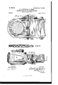
- FIG. 1 is a side view' illustrating the application of our invention to an engine-crank.
- Fig. 2 is a detail view of the lever controlled by the engineer.
- Fig. 3 is an enlarged section of the bearing of the connecting-rod constructed according to our invention.
- Fig. 4. is a partly-sectional view of the solid and hollow screws for adjusting the edges of the bearing.
- Fig. 5 is a plan view of the parts shown in Fig. 3.
- the numeral 1 indicates the piston-rod of an engine, the same being connected with a cross-head 2, that slides upon guides 3.
- the said cross-head 2 is connected with the crank-pin 5 by means of a connecting-rod 4, to which our improved bearing is applied.
- the crank-pin 5 projects from a'disk or crank 6, keyed upon the engineshaft 7-.
- the bearing is provided with the usual strap 8, within which are arranged two halfboxes 9 10.
- the half 10' sets close to the outer one 9 and is provided with opposite inclines on its outer side.
- the wedges 12 and 13 (see Fig. 3) work in frictional contact with such inclines of the half 10 and are adjusted simultaneously toward or from each other by means of a solid and hollow screw, whose construction and arrangement are as follows:
- the wedges 12 and 13 are preferably of the One of them is threaded interiorly with a right-hand thread and the other with a left-hand thread.
- a tubular screw 14:, Fig. 4 is screwed into these wedges and has a single continuous thread inside, as shown in Fig. 4.
- the ends of the screw 15 are made cylindrical and project through the sides of the strap 8.
- a nut 16 is screwed on the lower end, and a worm-wheel 17 is keyed on its upper end.
- the screw 15 thus constitutes practically a screw-shaft having its hearings in the strap 8. It is apparent that the opposite exterior threads on the hollow screw 14 correspond to and are adapted to work in the respective threads of the wedges 12 and 13, and consequently when the said screw 14 is rotated the wedges will move simultaneously toward or from each other.
- the shell or tubular screw lei abuts the inner side of the strap 8 and is secured to the solid screw 15 by means of pins or screws 18,
- a worm-shaft 21 arranged transversely on the cap-plate 19 and having bearings 22, which are secured to the latter.
- a star or wiper wheel 23 On one end of the worm-shaft 21 is keyed a star or wiper wheel 23, and adjacent to the latter is a circular ratchet 24, with which a spring-pawl 25 engages.
- Said pawl is secured to cap-plate 19 and made V-shaped at its free end, so that it has frictional engagement with the ratchet and is adapted to slide on the latter either way when the shaft 21 is rotated.
- the pawl obviously serves to lock the shaft and worm 17, so that they are immovable save when the trip-wheel 23 is acted upon.
- the means for thus acting on the trip-wheel are illustrated in Figs.
- a hand-lever 27 having an arm 27, arranged at an obtuse angle thereto.
- the free lower end of said arm carries two pins 30 and 31, which project laterally, as shown in Fig. 2.
- the lever-arm 27 is in the path of the tripwheel 23, and, as shown by dotted lines, the said wheel passes between the pins 30 31 when the lever 27 is set in its mid position.
- the lever is provided with a locking-dog 32, by which it is locked to the quadrant 33. Stops 34 limit the lateral movement of the lever in both directions.
- the movement of the pins or fingers 30 31 of the leverarm 27 can be adjusted by moving the stops 3% and the quadrant 33.
- the strap is mainly relieved of strain, which is taken up by the screwshaft.
- two wedges one balances the other in elfect on the rod and strap.
- the wedges can be moved one-thousandth of an inch, which is a very fine adj ustment.
- a bearing-adjuster of the class described the combination with a connectingrod and the wrist-pin of an engine crank or cross-head, of an adjustable half-box, wedges adapted to act thereon and threaded interiorly right and left, a screw-shaft working in said wedges, gearing for rotating the shaft in either direction and a tappet or trip device arranged in the path of said gearing and adapted to trip the same, for moving the wedges simultaneously toward or from each other, as required to tighten or loosen the bearing substantially as shown and described.
Description
. No. 689,727; Patentelk Dec. 24,1901,-
0'. E. K'ESTER & c-. n. oose. BEARING ADJUSTER FQR-GONNECTING RODS.
' (Application filed May 13, 1901.)
(No Model.) 2 Sheets-Sheet I.
A TTORNE )S m: NORRIS PETERS cu, wow-Lima, WASHINGTON, 0.1:.
No. 689,727. Patented Dec. 24, mm;
c. E. 'KESTEB & c. n. manna; BEARING ADJUSTER FOB CONNECTING RODS.
(Application filed my 18, 1901.)
2 Sheets-Shut 2.
4 glu h l I "H pl 11' arzes 6% "LHIIII I WITNESSES:
A rromvE'rs UNITED ST T-Es PATENT OFFICE.
CHARLES E. KESTER AND CHARLES R. MOORE, OF HILLSBORO, ILLINOIS.
BEARING ADJUSTER FOR CONN Ec'rme-Roos.
SPECIFICATION forming part of Letters Patent No. 689,727, dated December 24, 1901. Applicationlfiled May 13,1901. Serial No. 60.005. (No model.)
.and driving-wedgeare usually employed for tightening the strap holding the brasses which constitute the bearing of a connectingrod on the wrist-pin of an engine-crank. To adjust suchbearing requires that the engine shall be stopped, and since such adjustment .must be made quite frequently and consumes considerable time a corresponding expense is involved, especially in large establishments.
Our invention enables the adjustment to be made without stopping the engine or reducing its load or speed. If the hearing becomes too warm, itcan be slacked off a little, or if it bumps excessively the bearing may be tightened by the simple adjustment of a hand-lever under the control of the engineer. v In constructing our improved adjustable bearing We emplo'ytwo wedges, which work in frictional contact with inclined surfaceson one of the halves of the bearing, andby adjusting such wedges toward or from each other the bearing proper is tightened or loosened,as required. The wedgesfare moved simultaneously by a screwshaft and wormgear, and the latter is acted upon by a wiper or trip-wheel which is rotated intermittently or stepwise by the lever mechanism controlled by theengineer.
The details of construction, combination, and operation of parts are as hereinafter described,and shown in the accompanying drawings, in which Figure 1 is a side view' illustrating the application of our invention to an engine-crank. Fig. 2 is a detail view of the lever controlled by the engineer. Fig. 3 is an enlarged section of the bearing of the connecting-rod constructed according to our invention. Fig. 4. is a partly-sectional view of the solid and hollow screws for adjusting the edges of the bearing. Fig. 5 is a plan view of the parts shown in Fig. 3.
same width as the strap 8.
As shown in Fig. 1, the numeral 1 indicates the piston-rod of an engine, the same being connected with a cross-head 2, that slides upon guides 3. The said cross-head 2 is connected with the crank-pin 5 by means of a connecting-rod 4, to which our improved bearing is applied. The crank-pin 5 projects from a'disk or crank 6, keyed upon the engineshaft 7-. j
The bearing is provided with the usual strap 8, within which are arranged two halfboxes 9 10. The half 10' sets close to the outer one 9 and is provided with opposite inclines on its outer side. The wedges 12 and 13 (see Fig. 3) work in frictional contact with such inclines of the half 10 and are adjusted simultaneously toward or from each other by means of a solid and hollow screw, whose construction and arrangement are as follows: The wedges 12 and 13 are preferably of the One of them is threaded interiorly with a right-hand thread and the other with a left-hand thread. A tubular screw 14:, Fig. 4, is screwed into these wedges and has a single continuous thread inside, as shown in Fig. 4. The ends of the screw 15 are made cylindrical and project through the sides of the strap 8. A nut 16 is screwed on the lower end, and a worm-wheel 17 is keyed on its upper end. The screw 15 thus constitutes practically a screw-shaft having its hearings in the strap 8. It is apparent that the opposite exterior threads on the hollow screw 14 correspond to and are adapted to work in the respective threads of the wedges 12 and 13, and consequently when the said screw 14 is rotated the wedges will move simultaneously toward or from each other.
"The shell or tubular screw lei abuts the inner side of the strap 8 and is secured to the solid screw 15 by means of pins or screws 18,
If the position of the connecting-rod relative to the base is changed by putting in liners or washers, &c., for Wear, the movement of the pins or fingers 30 31 of the leverarm 27 can be adjusted by moving the stops 3% and the quadrant 33.
By using two wedges arranged and operated as described the strap is mainly relieved of strain, which is taken up by the screwshaft. In brief, by using two wedges one balances the other in elfect on the rod and strap. The wedges can be moved one-thousandth of an inch, which is a very fine adj ustment.
\Vhen the star or wiper wheel 23 is engaged to make an adjustment of the wedges, it is done just before compression begins or from the point where the crank-pin travels from the last quarter of the stroke to back center.
There is hence no pressure on the wedges, and they may he therefore very easily moved.
It is to be understood that our invention is applicable to any bearing where adjustable parts are employed.
What we claim is 1. In a bearing-adjuster of the class described, the combination with a connectingrod and the wrist-pin of an engine crank or cross-head, of an adjustable half-box, wedges adapted to act thereon and threaded interiorly right and left, a screw-shaft having reverse threads for engaging the wedges and means for rotating such shaftsubstantially as shown and described.
2. In a bearing-adjuster of the class described, the combination with a connectingrod and the wrist-pin of an engine crank or cross-head, of an adjustable half-box, wedges adapted to act thereon and threaded interiorly right and left, a screw-shaft working in said wedges, gearing for rotating the shaft in either direction and a tappet or trip device arranged in the path of said gearing and adapted to trip the same, for moving the wedges simultaneously toward or from each other, as required to tighten or loosen the bearing substantially as shown and described.
3. In a bearing-adjuster of the class de scribed, the combination with a connectingrod and the wrist-pin of an engine crank or cross-head, of an adjustable brass half-box,
wedges adapted to act thereon and threaded interiorly right and left, a screw-shaft working in said wedges,- gearing for rotating the said shaft and having a trip-wheel arranged as described, a tripping device arranged in the path of the said wheel and having two op posite parts adapted to engage the wheel on either side, and means for adjusting said tripping device for shifting the trip=wheel and thereby the wedges in either direction sub stantially as shown and described.
4. In a bearing-adjuster of the class de= scribed, the combination with a connectingrod and the wrist-pin of an engine crank or cross-head of an adjustable half-box, wedges adapted to act thereon and threaded interiorly right and left, a screw-shaft working in said wedges, a worm-wheel applied thereto,- a worm-shaft meshing with said wheel,- a star trip-wheel and ratchet fixed on said wormshaft, a pawl adapted to engage said ratchet,- a lever pivoted adjacent to the connectingrod and having an arm carrying lateral pins which may be brought into the path of the said trip-wheel for rotating it intermittently or stepwise in either direction, as required for adjusting the Wedges in either direction for tightening or loosening the bearing substantially as shown and described.
5. In a bearing-adjuster of the class described, the combination of a connecting-rod, wrist-pin, half-boxes, wedges and screw-shaft operating the said wedges, the worm-wheel, worm-shaft, trip-wheel and lever having an arm carrying lateral pins for engaging said trip-wheel as the crank rotates, and adjust- 10 its respective end portions, a screw shaft which passes through such hollow screw,
means for locking the two screws together the hollow screw abutting the inner sides of the strap and the solid screw having its bearings in. the latter, and means for rotating the com 15 pound screw-shaft substantially as shown and described.
CHARLES E. KESTER. CHARLES R. MOORE. Witnesses:
HENRY R. CRAWFORD, J. J. FREY.
Priority Applications (1)
| Application Number | Priority Date | Filing Date | Title |
|---|---|---|---|
| US6000501A US689727A (en) | 1901-05-13 | 1901-05-13 | Bearing-adjuster for connecting-rods. |
Applications Claiming Priority (1)
| Application Number | Priority Date | Filing Date | Title |
|---|---|---|---|
| US6000501A US689727A (en) | 1901-05-13 | 1901-05-13 | Bearing-adjuster for connecting-rods. |
Publications (1)
| Publication Number | Publication Date |
|---|---|
| US689727A true US689727A (en) | 1901-12-24 |
Family
ID=2758269
Family Applications (1)
| Application Number | Title | Priority Date | Filing Date |
|---|---|---|---|
| US6000501A Expired - Lifetime US689727A (en) | 1901-05-13 | 1901-05-13 | Bearing-adjuster for connecting-rods. |
Country Status (1)
| Country | Link |
|---|---|
| US (1) | US689727A (en) |
-
1901
- 1901-05-13 US US6000501A patent/US689727A/en not_active Expired - Lifetime
Similar Documents
| Publication | Publication Date | Title |
|---|---|---|
| US689727A (en) | Bearing-adjuster for connecting-rods. | |
| US273276A (en) | Feed-water adjustment for pumps | |
| US1645276A (en) | Adjustable nut | |
| US1942189A (en) | Mechanism for controlling engine valve mechanisms | |
| US837029A (en) | Rotary lithographic machine. | |
| US831822A (en) | Steam-engine. | |
| US85375A (en) | Improvement in treadles | |
| US1163345A (en) | Head-motion for concentrators. | |
| US3267760A (en) | Transmissions | |
| US1074548A (en) | Locomotive reversing-valve gear. | |
| US1310512A (en) | Ckosshead-guide fob engines | |
| US1188993A (en) | Platen-controlling mechanism for printing-presses. | |
| US2073971A (en) | Adjustment means for steering gears | |
| US491896A (en) | Mechanical movement | |
| US78733A (en) | Improved apparatus foe turning wrist-pins, crank-pins | |
| US805587A (en) | Valve-rod and wrist-pin connection. | |
| US790015A (en) | Pitman for die-presses. | |
| US1137757A (en) | Wrist-pin for felt-making machines. | |
| US1121705A (en) | Actuating means for fountain-rolls for printing-presses. | |
| US766498A (en) | Reversing-engine. | |
| US803491A (en) | Warping-machine. | |
| US288086A (en) | Micrometer-regulator for watches | |
| US1291017A (en) | Steering mechanism. | |
| US200639A (en) | Improvement in valve-gear for steam-engines | |
| US453599A (en) | Adjustable pitman |