US6896984B2 - Methods for reducing mass and volume of a fuel processor - Google Patents
Methods for reducing mass and volume of a fuel processor Download PDFInfo
- Publication number
- US6896984B2 US6896984B2 US10/133,597 US13359702A US6896984B2 US 6896984 B2 US6896984 B2 US 6896984B2 US 13359702 A US13359702 A US 13359702A US 6896984 B2 US6896984 B2 US 6896984B2
- Authority
- US
- United States
- Prior art keywords
- fuel processor
- reduction reactor
- fuel
- carbon monoxide
- reactor
- Prior art date
- Legal status (The legal status is an assumption and is not a legal conclusion. Google has not performed a legal analysis and makes no representation as to the accuracy of the status listed.)
- Expired - Fee Related, expires
Links
- 239000000446 fuel Substances 0.000 title claims abstract description 182
- 238000000034 method Methods 0.000 title claims abstract description 46
- XLYOFNOQVPJJNP-UHFFFAOYSA-N water Substances O XLYOFNOQVPJJNP-UHFFFAOYSA-N 0.000 claims abstract description 34
- 229910001868 water Inorganic materials 0.000 claims abstract description 34
- 238000004513 sizing Methods 0.000 claims abstract description 14
- UGFAIRIUMAVXCW-UHFFFAOYSA-N Carbon monoxide Chemical compound [O+]#[C-] UGFAIRIUMAVXCW-UHFFFAOYSA-N 0.000 claims description 45
- 229910002091 carbon monoxide Inorganic materials 0.000 claims description 45
- 239000001257 hydrogen Substances 0.000 claims description 17
- 229910052739 hydrogen Inorganic materials 0.000 claims description 17
- UFHFLCQGNIYNRP-UHFFFAOYSA-N Hydrogen Chemical compound [H][H] UFHFLCQGNIYNRP-UHFFFAOYSA-N 0.000 claims description 15
- 239000012530 fluid Substances 0.000 claims description 8
- 230000035945 sensitivity Effects 0.000 claims description 7
- OKTJSMMVPCPJKN-UHFFFAOYSA-N Carbon Chemical compound [C] OKTJSMMVPCPJKN-UHFFFAOYSA-N 0.000 claims description 6
- 229910052799 carbon Inorganic materials 0.000 claims description 6
- 238000012546 transfer Methods 0.000 claims description 5
- 238000011161 development Methods 0.000 abstract description 3
- 238000006243 chemical reaction Methods 0.000 description 13
- 238000013461 design Methods 0.000 description 9
- 239000007789 gas Substances 0.000 description 9
- 238000000629 steam reforming Methods 0.000 description 9
- CURLTUGMZLYLDI-UHFFFAOYSA-N Carbon dioxide Chemical compound O=C=O CURLTUGMZLYLDI-UHFFFAOYSA-N 0.000 description 8
- 229930195733 hydrocarbon Natural products 0.000 description 7
- 150000002430 hydrocarbons Chemical class 0.000 description 7
- VNWKTOKETHGBQD-UHFFFAOYSA-N methane Chemical compound C VNWKTOKETHGBQD-UHFFFAOYSA-N 0.000 description 6
- 239000003054 catalyst Substances 0.000 description 5
- 238000007254 oxidation reaction Methods 0.000 description 5
- 239000004215 Carbon black (E152) Substances 0.000 description 4
- 230000003466 anti-cipated effect Effects 0.000 description 4
- QVGXLLKOCUKJST-UHFFFAOYSA-N atomic oxygen Chemical compound [O] QVGXLLKOCUKJST-UHFFFAOYSA-N 0.000 description 4
- 239000001569 carbon dioxide Substances 0.000 description 4
- 229910002092 carbon dioxide Inorganic materials 0.000 description 4
- 239000007788 liquid Substances 0.000 description 4
- 230000003647 oxidation Effects 0.000 description 4
- 239000001301 oxygen Substances 0.000 description 4
- 229910052760 oxygen Inorganic materials 0.000 description 4
- 239000000376 reactant Substances 0.000 description 4
- OKKJLVBELUTLKV-UHFFFAOYSA-N Methanol Chemical compound OC OKKJLVBELUTLKV-UHFFFAOYSA-N 0.000 description 3
- 238000009826 distribution Methods 0.000 description 3
- 239000012528 membrane Substances 0.000 description 3
- IJGRMHOSHXDMSA-UHFFFAOYSA-N Atomic nitrogen Chemical compound N#N IJGRMHOSHXDMSA-UHFFFAOYSA-N 0.000 description 2
- LFQSCWFLJHTTHZ-UHFFFAOYSA-N Ethanol Chemical compound CCO LFQSCWFLJHTTHZ-UHFFFAOYSA-N 0.000 description 2
- 230000001186 cumulative effect Effects 0.000 description 2
- 238000010494 dissociation reaction Methods 0.000 description 2
- 239000003502 gasoline Substances 0.000 description 2
- 239000013529 heat transfer fluid Substances 0.000 description 2
- 150000002431 hydrogen Chemical class 0.000 description 2
- VUZPPFZMUPKLLV-UHFFFAOYSA-N methane;hydrate Chemical compound C.O VUZPPFZMUPKLLV-UHFFFAOYSA-N 0.000 description 2
- 239000000126 substance Substances 0.000 description 2
- 238000004458 analytical method Methods 0.000 description 1
- 238000013459 approach Methods 0.000 description 1
- 239000006227 byproduct Substances 0.000 description 1
- 239000007795 chemical reaction product Substances 0.000 description 1
- 238000002485 combustion reaction Methods 0.000 description 1
- 230000001143 conditioned effect Effects 0.000 description 1
- 239000000470 constituent Substances 0.000 description 1
- 230000003247 decreasing effect Effects 0.000 description 1
- 238000012938 design process Methods 0.000 description 1
- 238000010586 diagram Methods 0.000 description 1
- 230000005593 dissociations Effects 0.000 description 1
- 208000018459 dissociative disease Diseases 0.000 description 1
- 238000003487 electrochemical reaction Methods 0.000 description 1
- 238000005516 engineering process Methods 0.000 description 1
- 238000002347 injection Methods 0.000 description 1
- 239000007924 injection Substances 0.000 description 1
- 230000010354 integration Effects 0.000 description 1
- 238000004519 manufacturing process Methods 0.000 description 1
- 229910052757 nitrogen Inorganic materials 0.000 description 1
- 238000005457 optimization Methods 0.000 description 1
- 239000007800 oxidant agent Substances 0.000 description 1
- 230000001590 oxidative effect Effects 0.000 description 1
- 239000005518 polymer electrolyte Substances 0.000 description 1
- 239000007787 solid Substances 0.000 description 1
- 238000012360 testing method Methods 0.000 description 1
- 230000001052 transient effect Effects 0.000 description 1
Images


Classifications
-
- B—PERFORMING OPERATIONS; TRANSPORTING
- B01—PHYSICAL OR CHEMICAL PROCESSES OR APPARATUS IN GENERAL
- B01J—CHEMICAL OR PHYSICAL PROCESSES, e.g. CATALYSIS OR COLLOID CHEMISTRY; THEIR RELEVANT APPARATUS
- B01J19/00—Chemical, physical or physico-chemical processes in general; Their relevant apparatus
- B01J19/0006—Controlling or regulating processes
- B01J19/0033—Optimalisation processes, i.e. processes with adaptive control systems
-
- B—PERFORMING OPERATIONS; TRANSPORTING
- B60—VEHICLES IN GENERAL
- B60L—PROPULSION OF ELECTRICALLY-PROPELLED VEHICLES; SUPPLYING ELECTRIC POWER FOR AUXILIARY EQUIPMENT OF ELECTRICALLY-PROPELLED VEHICLES; ELECTRODYNAMIC BRAKE SYSTEMS FOR VEHICLES IN GENERAL; MAGNETIC SUSPENSION OR LEVITATION FOR VEHICLES; MONITORING OPERATING VARIABLES OF ELECTRICALLY-PROPELLED VEHICLES; ELECTRIC SAFETY DEVICES FOR ELECTRICALLY-PROPELLED VEHICLES
- B60L58/00—Methods or circuit arrangements for monitoring or controlling batteries or fuel cells, specially adapted for electric vehicles
- B60L58/30—Methods or circuit arrangements for monitoring or controlling batteries or fuel cells, specially adapted for electric vehicles for monitoring or controlling fuel cells
- B60L58/32—Methods or circuit arrangements for monitoring or controlling batteries or fuel cells, specially adapted for electric vehicles for monitoring or controlling fuel cells for controlling the temperature of fuel cells, e.g. by controlling the electric load
- B60L58/33—Methods or circuit arrangements for monitoring or controlling batteries or fuel cells, specially adapted for electric vehicles for monitoring or controlling fuel cells for controlling the temperature of fuel cells, e.g. by controlling the electric load by cooling
-
- C—CHEMISTRY; METALLURGY
- C01—INORGANIC CHEMISTRY
- C01B—NON-METALLIC ELEMENTS; COMPOUNDS THEREOF; METALLOIDS OR COMPOUNDS THEREOF NOT COVERED BY SUBCLASS C01C
- C01B3/00—Hydrogen; Gaseous mixtures containing hydrogen; Separation of hydrogen from mixtures containing it; Purification of hydrogen
- C01B3/02—Production of hydrogen or of gaseous mixtures containing a substantial proportion of hydrogen
- C01B3/32—Production of hydrogen or of gaseous mixtures containing a substantial proportion of hydrogen by reaction of gaseous or liquid organic compounds with gasifying agents, e.g. water, carbon dioxide, air
- C01B3/34—Production of hydrogen or of gaseous mixtures containing a substantial proportion of hydrogen by reaction of gaseous or liquid organic compounds with gasifying agents, e.g. water, carbon dioxide, air by reaction of hydrocarbons with gasifying agents
- C01B3/48—Production of hydrogen or of gaseous mixtures containing a substantial proportion of hydrogen by reaction of gaseous or liquid organic compounds with gasifying agents, e.g. water, carbon dioxide, air by reaction of hydrocarbons with gasifying agents followed by reaction of water vapour with carbon monoxide
-
- H—ELECTRICITY
- H01—ELECTRIC ELEMENTS
- H01M—PROCESSES OR MEANS, e.g. BATTERIES, FOR THE DIRECT CONVERSION OF CHEMICAL ENERGY INTO ELECTRICAL ENERGY
- H01M8/00—Fuel cells; Manufacture thereof
- H01M8/04—Auxiliary arrangements, e.g. for control of pressure or for circulation of fluids
- H01M8/04291—Arrangements for managing water in solid electrolyte fuel cell systems
-
- H—ELECTRICITY
- H01—ELECTRIC ELEMENTS
- H01M—PROCESSES OR MEANS, e.g. BATTERIES, FOR THE DIRECT CONVERSION OF CHEMICAL ENERGY INTO ELECTRICAL ENERGY
- H01M8/00—Fuel cells; Manufacture thereof
- H01M8/06—Combination of fuel cells with means for production of reactants or for treatment of residues
- H01M8/0606—Combination of fuel cells with means for production of reactants or for treatment of residues with means for production of gaseous reactants
- H01M8/0612—Combination of fuel cells with means for production of reactants or for treatment of residues with means for production of gaseous reactants from carbon-containing material
-
- H—ELECTRICITY
- H01—ELECTRIC ELEMENTS
- H01M—PROCESSES OR MEANS, e.g. BATTERIES, FOR THE DIRECT CONVERSION OF CHEMICAL ENERGY INTO ELECTRICAL ENERGY
- H01M8/00—Fuel cells; Manufacture thereof
- H01M8/06—Combination of fuel cells with means for production of reactants or for treatment of residues
- H01M8/0662—Treatment of gaseous reactants or gaseous residues, e.g. cleaning
-
- B—PERFORMING OPERATIONS; TRANSPORTING
- B01—PHYSICAL OR CHEMICAL PROCESSES OR APPARATUS IN GENERAL
- B01J—CHEMICAL OR PHYSICAL PROCESSES, e.g. CATALYSIS OR COLLOID CHEMISTRY; THEIR RELEVANT APPARATUS
- B01J2219/00—Chemical, physical or physico-chemical processes in general; Their relevant apparatus
- B01J2219/00049—Controlling or regulating processes
- B01J2219/00191—Control algorithm
-
- C—CHEMISTRY; METALLURGY
- C01—INORGANIC CHEMISTRY
- C01B—NON-METALLIC ELEMENTS; COMPOUNDS THEREOF; METALLOIDS OR COMPOUNDS THEREOF NOT COVERED BY SUBCLASS C01C
- C01B2203/00—Integrated processes for the production of hydrogen or synthesis gas
- C01B2203/02—Processes for making hydrogen or synthesis gas
- C01B2203/0205—Processes for making hydrogen or synthesis gas containing a reforming step
- C01B2203/0227—Processes for making hydrogen or synthesis gas containing a reforming step containing a catalytic reforming step
- C01B2203/0244—Processes for making hydrogen or synthesis gas containing a reforming step containing a catalytic reforming step the reforming step being an autothermal reforming step, e.g. secondary reforming processes
-
- C—CHEMISTRY; METALLURGY
- C01—INORGANIC CHEMISTRY
- C01B—NON-METALLIC ELEMENTS; COMPOUNDS THEREOF; METALLOIDS OR COMPOUNDS THEREOF NOT COVERED BY SUBCLASS C01C
- C01B2203/00—Integrated processes for the production of hydrogen or synthesis gas
- C01B2203/02—Processes for making hydrogen or synthesis gas
- C01B2203/0283—Processes for making hydrogen or synthesis gas containing a CO-shift step, i.e. a water gas shift step
- C01B2203/0288—Processes for making hydrogen or synthesis gas containing a CO-shift step, i.e. a water gas shift step containing two CO-shift steps
-
- C—CHEMISTRY; METALLURGY
- C01—INORGANIC CHEMISTRY
- C01B—NON-METALLIC ELEMENTS; COMPOUNDS THEREOF; METALLOIDS OR COMPOUNDS THEREOF NOT COVERED BY SUBCLASS C01C
- C01B2203/00—Integrated processes for the production of hydrogen or synthesis gas
- C01B2203/04—Integrated processes for the production of hydrogen or synthesis gas containing a purification step for the hydrogen or the synthesis gas
- C01B2203/0435—Catalytic purification
- C01B2203/044—Selective oxidation of carbon monoxide
-
- C—CHEMISTRY; METALLURGY
- C01—INORGANIC CHEMISTRY
- C01B—NON-METALLIC ELEMENTS; COMPOUNDS THEREOF; METALLOIDS OR COMPOUNDS THEREOF NOT COVERED BY SUBCLASS C01C
- C01B2203/00—Integrated processes for the production of hydrogen or synthesis gas
- C01B2203/04—Integrated processes for the production of hydrogen or synthesis gas containing a purification step for the hydrogen or the synthesis gas
- C01B2203/0465—Composition of the impurity
- C01B2203/047—Composition of the impurity the impurity being carbon monoxide
-
- C—CHEMISTRY; METALLURGY
- C01—INORGANIC CHEMISTRY
- C01B—NON-METALLIC ELEMENTS; COMPOUNDS THEREOF; METALLOIDS OR COMPOUNDS THEREOF NOT COVERED BY SUBCLASS C01C
- C01B2203/00—Integrated processes for the production of hydrogen or synthesis gas
- C01B2203/06—Integration with other chemical processes
- C01B2203/066—Integration with other chemical processes with fuel cells
-
- C—CHEMISTRY; METALLURGY
- C01—INORGANIC CHEMISTRY
- C01B—NON-METALLIC ELEMENTS; COMPOUNDS THEREOF; METALLOIDS OR COMPOUNDS THEREOF NOT COVERED BY SUBCLASS C01C
- C01B2203/00—Integrated processes for the production of hydrogen or synthesis gas
- C01B2203/08—Methods of heating or cooling
- C01B2203/0805—Methods of heating the process for making hydrogen or synthesis gas
- C01B2203/0838—Methods of heating the process for making hydrogen or synthesis gas by heat exchange with exothermic reactions, other than by combustion of fuel
- C01B2203/0844—Methods of heating the process for making hydrogen or synthesis gas by heat exchange with exothermic reactions, other than by combustion of fuel the non-combustive exothermic reaction being another reforming reaction as defined in groups C01B2203/02 - C01B2203/0294
-
- C—CHEMISTRY; METALLURGY
- C01—INORGANIC CHEMISTRY
- C01B—NON-METALLIC ELEMENTS; COMPOUNDS THEREOF; METALLOIDS OR COMPOUNDS THEREOF NOT COVERED BY SUBCLASS C01C
- C01B2203/00—Integrated processes for the production of hydrogen or synthesis gas
- C01B2203/14—Details of the flowsheet
- C01B2203/142—At least two reforming, decomposition or partial oxidation steps in series
-
- C—CHEMISTRY; METALLURGY
- C01—INORGANIC CHEMISTRY
- C01B—NON-METALLIC ELEMENTS; COMPOUNDS THEREOF; METALLOIDS OR COMPOUNDS THEREOF NOT COVERED BY SUBCLASS C01C
- C01B2203/00—Integrated processes for the production of hydrogen or synthesis gas
- C01B2203/16—Controlling the process
- C01B2203/1642—Controlling the product
- C01B2203/1647—Controlling the amount of the product
- C01B2203/1652—Measuring the amount of product
- C01B2203/1661—Measuring the amount of product the product being carbon monoxide
-
- C—CHEMISTRY; METALLURGY
- C01—INORGANIC CHEMISTRY
- C01B—NON-METALLIC ELEMENTS; COMPOUNDS THEREOF; METALLOIDS OR COMPOUNDS THEREOF NOT COVERED BY SUBCLASS C01C
- C01B2203/00—Integrated processes for the production of hydrogen or synthesis gas
- C01B2203/16—Controlling the process
- C01B2203/1685—Control based on demand of downstream process
-
- C—CHEMISTRY; METALLURGY
- C01—INORGANIC CHEMISTRY
- C01B—NON-METALLIC ELEMENTS; COMPOUNDS THEREOF; METALLOIDS OR COMPOUNDS THEREOF NOT COVERED BY SUBCLASS C01C
- C01B2203/00—Integrated processes for the production of hydrogen or synthesis gas
- C01B2203/80—Aspect of integrated processes for the production of hydrogen or synthesis gas not covered by groups C01B2203/02 - C01B2203/1695
- C01B2203/82—Several process steps of C01B2203/02 - C01B2203/08 integrated into a single apparatus
-
- Y—GENERAL TAGGING OF NEW TECHNOLOGICAL DEVELOPMENTS; GENERAL TAGGING OF CROSS-SECTIONAL TECHNOLOGIES SPANNING OVER SEVERAL SECTIONS OF THE IPC; TECHNICAL SUBJECTS COVERED BY FORMER USPC CROSS-REFERENCE ART COLLECTIONS [XRACs] AND DIGESTS
- Y02—TECHNOLOGIES OR APPLICATIONS FOR MITIGATION OR ADAPTATION AGAINST CLIMATE CHANGE
- Y02E—REDUCTION OF GREENHOUSE GAS [GHG] EMISSIONS, RELATED TO ENERGY GENERATION, TRANSMISSION OR DISTRIBUTION
- Y02E60/00—Enabling technologies; Technologies with a potential or indirect contribution to GHG emissions mitigation
- Y02E60/30—Hydrogen technology
- Y02E60/50—Fuel cells
-
- Y—GENERAL TAGGING OF NEW TECHNOLOGICAL DEVELOPMENTS; GENERAL TAGGING OF CROSS-SECTIONAL TECHNOLOGIES SPANNING OVER SEVERAL SECTIONS OF THE IPC; TECHNICAL SUBJECTS COVERED BY FORMER USPC CROSS-REFERENCE ART COLLECTIONS [XRACs] AND DIGESTS
- Y02—TECHNOLOGIES OR APPLICATIONS FOR MITIGATION OR ADAPTATION AGAINST CLIMATE CHANGE
- Y02T—CLIMATE CHANGE MITIGATION TECHNOLOGIES RELATED TO TRANSPORTATION
- Y02T90/00—Enabling technologies or technologies with a potential or indirect contribution to GHG emissions mitigation
- Y02T90/40—Application of hydrogen technology to transportation, e.g. using fuel cells
Definitions
- the present invention relates generally to fuel cell systems and more particularly to methods for designing a fuel processor having a reduced size (i.e., the mass and volume) for a given fuel cell system application.
- Fuel cell systems have been proposed for use in electrical vehicular power plants to replace internal combustion engines. Such systems typically include a proton exchange membrane (PEM) type fuel cell in which hydrogen is supplied as the fuel to the anode and oxygen is supplied as the oxidant to the cathode of the fuel cell.
- PEM fuel cells include a membrane electrode assembly (MEA) comprising a thin, proton transmissive, non-electrically conductive solid polymer electrolyte membrane having the anode catalyst on one of its faces and the cathode catalyst on the opposite face.
- MEAs are relatively expensive to manufacture and require certain conditions, including proper water management and humidification and control of catalyst fouling constituents such as carbon monoxide (CO) for effective operation.
- a plurality of individual cells are commonly arranged in series together to form a fuel cell stack. Typical arrangements of multiple cells in a stack are described in U.S. Pat. No. 5,763,113, assigned to General Motors Corporation.
- a liquid fuel such as a liquid hydrocarbon (e.g., methanol, ethanol or gasoline) as the source of hydrogen for the fuel cell.
- a liquid fuel such as a liquid hydrocarbon (e.g., methanol, ethanol or gasoline)
- a liquid fuel for the vehicle are easy to store onboard and there is a nationwide infrastructure for supplying liquid fuels.
- Such fuels must be dissociated to release the hydrogen content thereof for fueling the fuel cell.
- the dissociation reaction is accomplished within a chemical fuel processor or reformer.
- the fuel processor typically contains multiple reactors wherein the fuel reacts with steam and air to yield a reformate gas comprising primarily hydrogen and carbon dioxide.
- a primary reactor is utilized to dissociate the hydrocarbon fuel into hydrogen, carbon dioxide, carbon monoxide, water and methane. Secondary or CO reduction reactors are used to reduce the CO levels in the reformate stream.
- the feasibility of using a fuel cell system as a power source can depend on whether the size of the system is appropriate for a particular use. This is particularly so in vehicular applications, where the mass and volume of a vehicle directly influence its fuel efficiency and speed. Another factor affecting fuel cell system performance is the amount of water available within the system for input to reactions requiring water as a reactant. It is desirable to maintain a water-neutral fuel cell system and at the same time to provide enough water to support efficient fuel cell performance. Thus, steam to carbon (S/C) ratio is an important consideration in fuel processor design.
- S/C steam to carbon
- Fuel processors for a fuel cell system have heretofore been designed in the following manner.
- a fuel processor is typically designed with primary emphasis on operational efficiency at a maximum power operating point and secondary emphasis on other specifications such as turndown ratio, acceptable start-up duration, and transient performance.
- a maximum-power, steady-state flow mechanization is used to predict the carbon monoxide concentration of the primary reactor.
- the CO reduction reactors are then sized to reduce the carbon monoxide levels to a sufficiently high quality for the fuel cell stack at the maximum power operating point.
- the present invention provides a method for optimizing the size (i.e., mass and volume) of a fuel processor for use in a fuel cell system for providing electrical power in a plurality of power ranges.
- the method includes maximizing water availability in the fuel cell system to provide for peak system operational efficiency in a “most-used” power range, while sizing fuel processor components to achieve a maximum power level albeit at a less than optimal efficiency.
- the above method allows development of a fuel processor that has significantly lower total mass and volume and a shorter start-up time than conventionally-designed processors, but which can perform at a desired maximum power.
- FIG. 1 is a simplified schematic diagram depicting a fuel cell system
- FIG. 2 is a graph of a distribution of power from a fuel cell system relative to cumulative percentage of time for a plurality of power level ranges in a vehicular application;
- FIG. 3 is a flow chart of a design optimization method for reducing the size of a fuel processor according to a preferred embodiment of the present invention
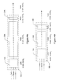
- FIG. 4A is a schematic representation of a fuel processor designed according to conventional fuel processor methodology.
- FIG. 4B is a schematic representation of a fuel processor designed according to the principles of the present invention.
- FIG. 1 A fuel processor for converting hydrocarbons such as gasoline into a hydrogen-containing reformate stream for use by a fuel cell system is shown in FIG. 1 .
- the present invention in one preferred embodiment is a method for optimizing the size (i.e., mass and volume) of a fuel processor for use in a fuel cell system.
- a fuel cell system 10 is shown in FIG. 1 for the purpose of teaching generally the various components of an exemplary fuel cell system.
- the embodiment of the present invention is described herein with reference to components of the fuel processor shown in FIG. 1 , it should be understood that the invention is not limited by the components and/or arrangements of components shown in FIG. 1 .
- Embodiments of the present invention can be used to design fuel processors having components and configurations that may differ from those shown in FIG. 1 .
- a fuel cell system 8 includes a fuel processor 10 having a primary reactor 12 for catalytically reacting a reformable hydrocarbon fuel in the form of a fuel stream 14 , water in the form of a steam stream 16 and air in the form of an air stream 18 .
- the reformable hydrocarbon fuel in fuel stream 14 undergoes dissociation in the presence of steam in steam stream 16 and air in air stream 18 to produce the hydrogen-containing reformate which is exhausted from the primary reactor 12 in a reformats stream 20 .
- the primary reactor 12 takes the form of an autothermal reformer in which the fuel stream 14 and steam stream 16 are mixed with the air stream 18 and passed sequentially through two reactor sections—a partial oxidation (POx) section and a steam reforming (SR) section.
- POx implies predominantly reaction between fuel and air
- SR implies predominantly reaction between fuel and water.
- POx implies predominantly reaction between fuel and air
- the predominantly POx reactions are exothermic and the predominantly SR reactions are endothermic, so that significantly all of the heat generated in the POx is carried into the SR.
- the fuel reacts exothermally with a sub-stoichiometric amount of air to produce carbon monoxide, hydrogen and lower hydrocarbons such as methane.
- the reaction in the POx section is typically fuel-rich.
- the hot POx reaction products, along with steam introduced with the fuel, pass into the SR section where the lower hydrocarbons react with steam to produce a reformate gas comprised principally of hydrogen, carbon dioxide, carbon monoxide, nitrogen, water, and methane.
- the steam reforming reaction is endothermic, and the heat required for this reaction is provided from the heat generated by the exothermic POx reaction and carried forward into the SR section by the POx effluent.
- the fuel processor 10 also includes a water gas shift (WGS) reactor 22 and a preferential oxidation reactor (PrOx) 24 which are used to reduce the level of carbon monoxide in the reformate stream 20 to acceptable levels, for example, below 20 ppm.
- Reformate stream 20 enters the WGS reactor 22 and therein reacts with excess steam from steam stream 16 not consumed in the primary reactor 12 .
- additional steam may be added to the WGS 22 in the form of a steam stream 38 to produce carbon dioxide and hydrogen from the carbon monoxide and water.
- the WGS reactor 32 preferably includes a high temperature shift (HTS) section and a low temperature shift (LTS) section.
- the water gas shift reaction is conducted as a primary CO reduction to consume a substantial amount (to a level of about 0.5% to 1.0% on a molar basis) of the carbon monoxide in the reformate stream 20 .
- Reformate stream 20 exits the WGS reactor 22 and enters the preferential oxidation (PrOx) reactor 24 where it is catalytically reacted with oxygen in the form of an air stream 40 .
- the preferential oxidation reaction is conducted as a secondary CO reduction to consume essentially all of, or at least most of, the residual carbon monoxide (to a level less than 100 parts per million) without consuming excessive quantities of hydrogen.
- the feed streams 14 , 16 , 18 , 20 , 28 , 38 , 40 of the various reactors and sections thereof may be conditioned (i.e., heated or cooled) via heat exchangers, water injection or other heat transfer means (not shown) to a suitable temperature based on the operational temperature of the specific component.
- exemplary operational temperatures of the components of the fuel cell system can be found in the literature, and by way of background are provided in Table 1 below:
- Air stream 28 is reacted in fuel cell stack 26 with reformate stream 20 exiting PrOx reactor 24 .
- the hydrogen in reformate stream 20 reacts with air stream 28 in an electrochemical reaction in the presence of the catalyst, whereby electrical energy is produced and water is generated as a by-product of the reaction.
- the reformate stream 20 enters the fuel cell stack 26 for reaction.
- Anode exhaust or effluent 30 from the anode side of the fuel cell stack 26 typically contains some unreacted hydrogen.
- Cathode exhaust or effluent 32 from the cathode side of the fuel cell 26 may contain some unreacted oxygen.
- anode effluent 30 can be combusted, catalytically or thermally, in the combustor 34 with oxygen provided to the combustor 30 from the cathode effluent stream 32 depending on system operating conditions.
- the combustor 34 discharges an exhaust stream 36 to the environment and the heat generated thereby may be directed to the fuel processor 10 as needed.
- the present invention is directed to a method for optimizing the size (i.e., mass and volume) of the fuel processor 10 for use in a fuel cell system 8 for providing electrical power in a plurality of power ranges.
- the method includes maximizing water availability and thus the steam to carbon (S/C) ratio of the fuel processor 10 to provide for peak operational efficiency in a most-used power range, while sizing the individual components of the fuel processor 10 to achieve a desired maximum power. That is to say that the fuel processor maximizes the S/C ratio which thermally balances the most-used power range to optimize performance in that power range and to obtain low carbon monoxide levels from the WGS reactor 22 .
- S/C steam to carbon
- the method further includes determining power level ranges that the fuel cell system 8 is to provide, determining percentages of time during which the fuel cell system 8 is to provide power in each of the ranges, and determining the most-used power range from the ranges and the percentages.
- FIG. 2 a distribution of power from a fuel cell system relative to cumulative percentage of time is depicted for a plurality of drive cycles in a motor vehicle application.
- Five driving schedules are plotted including City, Highway, NEDC, US06 and “Real-World.”
- the power demands in kilowatts as set forth in Table 2 can be evaluated from this data.
- volume and mass for a fuel processor are optimized according to steps shown in flow chart 100 of FIG. 3 .
- Specifications for the fuel cell system application to be implemented are determined and analyzed at step 102 . Such specifications include a maximum power level at which the system is to operate and a most-used power range for system operation as described above.
- Working fluids for heat transfer within the system also are analyzed at step 104 . For proper reactor operation, heat must be removed from the reformate between the primary reactor 12 and WGS 22 , and between the WGS 22 and the PrOx 24 . To increase fuel processor efficiency, heat also needs to be added to the steam stream 16 and the air stream 18 . These heat exchanges can be done in a variety of ways. Deciding the type of heat transfer fluid is an important initial step.
- an intermediate heat transfer working fluid such as oil provides flexibility in thermal control because the oil can be easily routed to each location.
- the oil flow rate can be controlled independently of the fuel processor process stream flows 14 , 16 , 18 , 38 , and 40 .
- the oil adds mass to the fuel processor which could delay the heat-up and therefore startup rate.
- one or more of the process fluids such as the steam stream 16 and the air stream 18 could be used as the heat transfer fluid. This approach minimizes fuel processor mass, but makes thermal control more challenging since the flow rates of the process fluids are not independent but a function of the fuel processor operating condition.
- An average S/C ratio anticipated to be available in the fuel cell system is computed at step 106 .
- a presently preferred method for distributing water in a fuel cell system includes transporting water via a water transfer device as described in pending U.S. application Ser. No. 09/910,331 now U.S. Pat. No. 6,630,260 filed Jul. 20, 2001 which is commonly owned by the assignee of the present invention and the disclosure of which is expressly incorporated herein by reference herein.
- variable pressure operation may be incorporated into the fuel cell system design to maximize water available while maintaining water neutrality of the system.
- a presently preferred method for variable pressure operation is described in pending U.S. application Ser. No. 09/584,210 now U.S. Pat. No.
- Fuel cell system mechanization options are analyzed at step 108 .
- steady-state modeling may be used to investigate steady-state flow mechanization options for fuel processor operation at selected power ranges in which the vehicle is anticipated to be operated.
- the sensitivity of the fuel processor 10 to bulk water availability during system operation in the most-used power range is analyzed at a step 110 to maximize the S/C ratio.
- steam input may occur at multiple locations including steam stream 16 and steam stream 38 .
- steam input may be provided incrementally within the primary reactor 12 or the WGS reactor, for example staged between the HTS and LTS sections of the WGS reactor 22 .
- a sensitivity factor may be computed as a function of the input location and the input quantity in view of the bulk water anticipated to be available in the fuel cell system. In general, adding steam improves the performance (CO reduction ability) of either an HTS or LTS. Using chemical reactor modeling and testing, the optimum distribuiton of steam can be determined that will result in the lowest total mass and volume.
- the steady-state flow mechanization for the most-used power range is used to estimate the concentration of the carbon monoxide in the reformate stream 20 exiting the primary reactor 12 at step 112 .
- the WGS reactor 22 is sized to reduce the carbon monoxide output concentration to a low level (e.g., between about 0.5 and 1.0 percent on a molar basis) in the most-used power range.
- a mid-power or 50% power level would be used to size the WGS reactor for the automotive application described in FIG. 2 .
- the mid-power steady-state flow mechanization again can be used, as previously described at step 110 , to optimize the water distribution in the fuel cell system in the most-used power range.
- the fuel processor mechanization is analyzed, at a step 114 to estimate the steady-state flow for a maximum power level at which the system is anticipated to operate.
- the maximum power mechanization is used to estimate the concentration of carbon monoxide in the reformate stream 20 exiting the WGS reactor 22 .
- the PrOx reactor 26 is sized to reduce the carbon monoxide output concentration to less than 100 ppm.
- the foregoing steps are repeated at step 116 as desired, in varying order and frequency as desired, to optimize the size of the various fuel processor components which maximizes power efficiency in the most-used power range and that delivers stack-grade hydrogen sufficient to support system operation at the maximum power level.
- an optimized fuel processor mechanization may be selected based on minimizing the total fuel processor volume or mass.
- the foregoing method yields a fuel processor design that has a peak efficiency in a most-used power range. That is to that the fuel processor maximizes the S/C ratio which thermally balances the most-used power range to optimize performance in that power range and to obtain low carbon monoxide levels from the WGS reactor 22 for increased efficiency. Heat integration and a less-than-optimal S/C ratio will occur when the system operates at a maximum power level, thus resulting in a higher CO concentration from the WGS reactor 20 (on the order of about 1 to 2 molar percent). While the S/C ratio is not optimized at full power (that is, higher levels of S/C could be vaporized), the S/C ratio nevertheless is higher at full power than in a conventionally designed fuel processor system.
- the PrOx reactor 24 is sized to consume carbon monoxide produced at full power and consequently configured to consume more hydrogen.
- a fuel processor 10 is provided that can operate at a desired full power level albeit at less than peak efficiency.
- FIGS. 4A and 4B illustrate illustrate how implementing the foregoing method can result in a fuel processor design having reduced size (i.e., mass and volume).
- FIG. 4A illustrates a conventionally-designed fuel processor 10 A
- FIG. 4B illustrates a fuel processor 10 B designed in accordance with principles of the present invention.
- a more active catalyst is used than in FIG. 4A
- the size of the primary reactor 12 B is only slightly increased, approximately 0.001 liters per kilowatt H 2 (l/kWH 2 ) or on the order of approximately 3.33% larger, over that of primary reactor 12 A.
- the size of the PrOx reactor 24 B is significantly increased, approximately 0.0096 l/kWH 2 or on the order of approximately 71.6% larger, than the PrOx reactor 24 A to support preferential oxidation at full power as a result of the increase in the carbon monoxide content from the WGS 22 B.
- the size of the WGS reactor 22 B is significantly reduced, approximately 0.075 l/kWH 2 or on the order of approximately 60.5% smaller, than that of the WGS reactor 22 A.
- the overall mass and volume of the fuel processor 10 is significantly reduced, approximately 0.0644 l/kWH 2 or on the order of approximately 38% smaller, as compared to fuel processor 10 A.
- Utilizing the method of the present invention typically increases the size of a primary reactor 12 and the PrOx reactor 24 combination by about 24.4% while decreasing the size of the WGS reactor 22 by about 60.5% over those implemented in conventionally-designed fuel processors.
- the size of fuel processors designed according to the above described method are at least about 30%, and typically about 35% to 45%, smaller than those of conventionally-designed fuel processors.
- a conventionally-designed fuel processor typically has a ratio of WGS reactor volume to total fuel processor volume (V wgs /V fp ) of between about 65% and 85%
- V wgs /V fp ratio of WGS reactor volume to total fuel processor volume
- the present invention has been described in the context of a fuel processor for use in a fuel cell system for providing electrical power in a plurality of power ranges.
- the design methodology described herein has a broader range of application to fuel processor design in general.
- the most-used power range and the maximum power level are defined in terms of the electrical power demands of the fuel cell system. Since a precise correlation exists between the reactant gas flows and the power output for a given fuel cell (that is to say the electrochemical potential of the fuel cell), the operating range could be defined in terms of the power of the reactant gas, and thus sizing of the components of the fuel processor based upon a most-used power range and a maximum power level of the reactant gas.
Landscapes
- Engineering & Computer Science (AREA)
- Chemical & Material Sciences (AREA)
- Chemical Kinetics & Catalysis (AREA)
- Sustainable Development (AREA)
- Sustainable Energy (AREA)
- Life Sciences & Earth Sciences (AREA)
- Electrochemistry (AREA)
- Organic Chemistry (AREA)
- General Chemical & Material Sciences (AREA)
- Manufacturing & Machinery (AREA)
- Transportation (AREA)
- Mechanical Engineering (AREA)
- Power Engineering (AREA)
- Health & Medical Sciences (AREA)
- General Health & Medical Sciences (AREA)
- Combustion & Propulsion (AREA)
- Inorganic Chemistry (AREA)
- Automation & Control Theory (AREA)
- Fuel Cell (AREA)
- Hydrogen, Water And Hydrids (AREA)
Abstract
A method for designing a fuel processor having an optimized size (i.e., volume and mass) for use in a fuel cell system which provides electrical power in a plurality of power ranges. The method includes maximizing water availability in the fuel cell system and sizing the first CO reduction reactor to provide for peak fuel cell system operational efficiency in a most-used power range while sizing the second CO reduction reactor to ensure the fuel processor can components to operate at a desired maximum power. The method allows development of a fuel processor that has significantly lower total mass and volume, and shorter start-up time, than conventionally designed processors, yet can perform at a desired maximum power.
Description
The present invention relates generally to fuel cell systems and more particularly to methods for designing a fuel processor having a reduced size (i.e., the mass and volume) for a given fuel cell system application.
Fuel cell systems have been proposed for use in electrical vehicular power plants to replace internal combustion engines. Such systems typically include a proton exchange membrane (PEM) type fuel cell in which hydrogen is supplied as the fuel to the anode and oxygen is supplied as the oxidant to the cathode of the fuel cell. PEM fuel cells include a membrane electrode assembly (MEA) comprising a thin, proton transmissive, non-electrically conductive solid polymer electrolyte membrane having the anode catalyst on one of its faces and the cathode catalyst on the opposite face. These MEAs are relatively expensive to manufacture and require certain conditions, including proper water management and humidification and control of catalyst fouling constituents such as carbon monoxide (CO) for effective operation. A plurality of individual cells are commonly arranged in series together to form a fuel cell stack. Typical arrangements of multiple cells in a stack are described in U.S. Pat. No. 5,763,113, assigned to General Motors Corporation.
For vehicular applications, it may be desirable to use a liquid fuel such as a liquid hydrocarbon (e.g., methanol, ethanol or gasoline) as the source of hydrogen for the fuel cell. Such liquid fuels for the vehicle are easy to store onboard and there is a nationwide infrastructure for supplying liquid fuels. However, such fuels must be dissociated to release the hydrogen content thereof for fueling the fuel cell. The dissociation reaction is accomplished within a chemical fuel processor or reformer. The fuel processor typically contains multiple reactors wherein the fuel reacts with steam and air to yield a reformate gas comprising primarily hydrogen and carbon dioxide. A primary reactor is utilized to dissociate the hydrocarbon fuel into hydrogen, carbon dioxide, carbon monoxide, water and methane. Secondary or CO reduction reactors are used to reduce the CO levels in the reformate stream.
The feasibility of using a fuel cell system as a power source can depend on whether the size of the system is appropriate for a particular use. This is particularly so in vehicular applications, where the mass and volume of a vehicle directly influence its fuel efficiency and speed. Another factor affecting fuel cell system performance is the amount of water available within the system for input to reactions requiring water as a reactant. It is desirable to maintain a water-neutral fuel cell system and at the same time to provide enough water to support efficient fuel cell performance. Thus, steam to carbon (S/C) ratio is an important consideration in fuel processor design.
Fuel processors for a fuel cell system have heretofore been designed in the following manner. A fuel processor is typically designed with primary emphasis on operational efficiency at a maximum power operating point and secondary emphasis on other specifications such as turndown ratio, acceptable start-up duration, and transient performance. A maximum-power, steady-state flow mechanization is used to predict the carbon monoxide concentration of the primary reactor. The CO reduction reactors are then sized to reduce the carbon monoxide levels to a sufficiently high quality for the fuel cell stack at the maximum power operating point.
Since fuel processors for automotive applications are in an early state of development, no alternate design methods or strategies currently are known that utilize existing technology to optimize the size (i.e., mass and volume) of the fuel processor. Although a maximum-power steady-state flow mechanization currently is analyzed in the fuel processor design process, it would be desirable also to analyze fuel processor operation at a plurality of power levels and to configure a fuel processor for efficient performance for the power levels at which it operates most of the time.
The present invention provides a method for optimizing the size (i.e., mass and volume) of a fuel processor for use in a fuel cell system for providing electrical power in a plurality of power ranges. The method includes maximizing water availability in the fuel cell system to provide for peak system operational efficiency in a “most-used” power range, while sizing fuel processor components to achieve a maximum power level albeit at a less than optimal efficiency. The above method allows development of a fuel processor that has significantly lower total mass and volume and a shorter start-up time than conventionally-designed processors, but which can perform at a desired maximum power.
Further areas of applicability of the present invention will become apparent from the detailed description provided hereinafter. It should be understood that the detailed description and specific examples, while indicating the preferred embodiment of the invention, are intended for purposes of illustration only and are not intended to limit the scope of the invention.
The various features, advantages and other uses of the present invention will become more apparent by referring to the following description and drawings in which:
The following description of the preferred embodiment is merely exemplary in nature and is in no way intended to limit the invention, its application, or uses.
A fuel processor for converting hydrocarbons such as gasoline into a hydrogen-containing reformate stream for use by a fuel cell system is shown in FIG. 1. The present invention in one preferred embodiment is a method for optimizing the size (i.e., mass and volume) of a fuel processor for use in a fuel cell system. Accordingly, a fuel cell system 10 is shown in FIG. 1 for the purpose of teaching generally the various components of an exemplary fuel cell system. Although the embodiment of the present invention is described herein with reference to components of the fuel processor shown in FIG. 1 , it should be understood that the invention is not limited by the components and/or arrangements of components shown in FIG. 1. Embodiments of the present invention can be used to design fuel processors having components and configurations that may differ from those shown in FIG. 1.
As shown in FIG. 1 , a fuel cell system 8 includes a fuel processor 10 having a primary reactor 12 for catalytically reacting a reformable hydrocarbon fuel in the form of a fuel stream 14, water in the form of a steam stream 16 and air in the form of an air stream 18. The reformable hydrocarbon fuel in fuel stream 14 undergoes dissociation in the presence of steam in steam stream 16 and air in air stream 18 to produce the hydrogen-containing reformate which is exhausted from the primary reactor 12 in a reformats stream 20.
In the presently preferred embodiment, the primary reactor 12 takes the form of an autothermal reformer in which the fuel stream 14 and steam stream 16 are mixed with the air stream 18 and passed sequentially through two reactor sections—a partial oxidation (POx) section and a steam reforming (SR) section. POx implies predominantly reaction between fuel and air and SR implies predominantly reaction between fuel and water. However, it is to be understood that there is some overlap in the type of reactions occurring in the POx and SR sections which combine to perform as an autothermal reformer.
In an autothermal reformer, the predominantly POx reactions are exothermic and the predominantly SR reactions are endothermic, so that significantly all of the heat generated in the POx is carried into the SR. In the POx section, the fuel reacts exothermally with a sub-stoichiometric amount of air to produce carbon monoxide, hydrogen and lower hydrocarbons such as methane. The reaction in the POx section is typically fuel-rich. The hot POx reaction products, along with steam introduced with the fuel, pass into the SR section where the lower hydrocarbons react with steam to produce a reformate gas comprised principally of hydrogen, carbon dioxide, carbon monoxide, nitrogen, water, and methane. The steam reforming reaction is endothermic, and the heat required for this reaction is provided from the heat generated by the exothermic POx reaction and carried forward into the SR section by the POx effluent.
The fuel processor 10 also includes a water gas shift (WGS) reactor 22 and a preferential oxidation reactor (PrOx) 24 which are used to reduce the level of carbon monoxide in the reformate stream 20 to acceptable levels, for example, below 20 ppm. Reformate stream 20 enters the WGS reactor 22 and therein reacts with excess steam from steam stream 16 not consumed in the primary reactor 12. Optionally, additional steam may be added to the WGS 22 in the form of a steam stream 38 to produce carbon dioxide and hydrogen from the carbon monoxide and water. The WGS reactor 32 preferably includes a high temperature shift (HTS) section and a low temperature shift (LTS) section. The water gas shift reaction is conducted as a primary CO reduction to consume a substantial amount (to a level of about 0.5% to 1.0% on a molar basis) of the carbon monoxide in the reformate stream 20. Reformate stream 20 exits the WGS reactor 22 and enters the preferential oxidation (PrOx) reactor 24 where it is catalytically reacted with oxygen in the form of an air stream 40. The preferential oxidation reaction is conducted as a secondary CO reduction to consume essentially all of, or at least most of, the residual carbon monoxide (to a level less than 100 parts per million) without consuming excessive quantities of hydrogen.
The feed streams 14, 16, 18, 20, 28, 38, 40 of the various reactors and sections thereof may be conditioned (i.e., heated or cooled) via heat exchangers, water injection or other heat transfer means (not shown) to a suitable temperature based on the operational temperature of the specific component. Exemplary operational temperatures of the components of the fuel cell system can be found in the literature, and by way of background are provided in Table 1 below:
| TABLE 1 | |||
| Component | Operational Temperature | ||
| ATR | 600° C.-1000° C. | ||
| WGS- |
400° C.-550° C. | ||
| WGS-LTS | 200° C.-300° C. | ||
| PrOx | 150° C.-250° C. | ||
| Fuel Cell Stack | 75° C.-100° C. | ||
The present invention is directed to a method for optimizing the size (i.e., mass and volume) of the fuel processor 10 for use in a fuel cell system 8 for providing electrical power in a plurality of power ranges. Although the present invention is described herein with respect to a vehicular application, it can be utilized for other applications, including stationary applications. The method includes maximizing water availability and thus the steam to carbon (S/C) ratio of the fuel processor 10 to provide for peak operational efficiency in a most-used power range, while sizing the individual components of the fuel processor 10 to achieve a desired maximum power. That is to say that the fuel processor maximizes the S/C ratio which thermally balances the most-used power range to optimize performance in that power range and to obtain low carbon monoxide levels from the WGS reactor 22.
The method further includes determining power level ranges that the fuel cell system 8 is to provide, determining percentages of time during which the fuel cell system 8 is to provide power in each of the ranges, and determining the most-used power range from the ranges and the percentages. With reference to FIG. 2 , a distribution of power from a fuel cell system relative to cumulative percentage of time is depicted for a plurality of drive cycles in a motor vehicle application. For purposes of illustration, the particular vehicle has a curb mass of 1000 kg and coefficient of drag, Cd=0.2. Five driving schedules are plotted including City, Highway, NEDC, US06 and “Real-World.” The power demands in kilowatts as set forth in Table 2 can be evaluated from this data.
| TABLE 2 | |||||
| | MAX | 95% | 50 | ||
| CITY |
| 25 | 12 | 12.5 | ||
| | 21 | 14 | 10.5 | |
| | 26 | 13 | 13 | |
| US06 | 53 | 18 | 26.5 | |
| | 56 | 31 | 28 | |
It can be seen from this data that this particular motor vehicle spends at least 90% of the time operating at and below 50 percent of the required maximum power level. Thus, the efficiency of the fuel processor for this motor vehicle application may be optimized for operation at 50 percent power, while providing the fuel processor with a capacity to supply maximum power required by the application. Because the water gas shift reaction is kinetically limited, the
More specifically, volume and mass for a fuel processor are optimized according to steps shown in flow chart 100 of FIG. 3. Specifications for the fuel cell system application to be implemented are determined and analyzed at step 102. Such specifications include a maximum power level at which the system is to operate and a most-used power range for system operation as described above. Working fluids for heat transfer within the system also are analyzed at step 104. For proper reactor operation, heat must be removed from the reformate between the primary reactor 12 and WGS 22, and between the WGS 22 and the PrOx 24. To increase fuel processor efficiency, heat also needs to be added to the steam stream 16 and the air stream 18. These heat exchanges can be done in a variety of ways. Deciding the type of heat transfer fluid is an important initial step. Selecting an intermediate heat transfer working fluid such as oil provides flexibility in thermal control because the oil can be easily routed to each location. The oil flow rate can be controlled independently of the fuel processor process stream flows 14, 16, 18, 38, and 40. The oil, however, adds mass to the fuel processor which could delay the heat-up and therefore startup rate. Instead of using an intermediate fluid such as oil, one or more of the process fluids, such as the steam stream 16 and the air stream 18 could be used as the heat transfer fluid. This approach minimizes fuel processor mass, but makes thermal control more challenging since the flow rates of the process fluids are not independent but a function of the fuel processor operating condition.
An average S/C ratio anticipated to be available in the fuel cell system is computed at step 106. A presently preferred method for distributing water in a fuel cell system includes transporting water via a water transfer device as described in pending U.S. application Ser. No. 09/910,331 now U.S. Pat. No. 6,630,260 filed Jul. 20, 2001 which is commonly owned by the assignee of the present invention and the disclosure of which is expressly incorporated herein by reference herein. Alternately, variable pressure operation may be incorporated into the fuel cell system design to maximize water available while maintaining water neutrality of the system. A presently preferred method for variable pressure operation is described in pending U.S. application Ser. No. 09/584,210 now U.S. Pat. No. 6,815,106 filed May 31, 2000 which is commonly owned by the assignee of the present invention and the disclosure of which is expressly incorporated herein by reference herein. Fuel cell system mechanization options are analyzed at step 108. For example, in the above described motor vehicle application, steady-state modeling may be used to investigate steady-state flow mechanization options for fuel processor operation at selected power ranges in which the vehicle is anticipated to be operated.
The present embodiment will now be discussed with respect to analyzing one such option for fuel processor mechanization. For one of the mechanizations being analyzed for possible implementation, the sensitivity of the fuel processor 10 to bulk water availability during system operation in the most-used power range is analyzed at a step 110 to maximize the S/C ratio. For example, steam input may occur at multiple locations including steam stream 16 and steam stream 38. While not shown one skilled in the art will recognize that steam input may be provided incrementally within the primary reactor 12 or the WGS reactor, for example staged between the HTS and LTS sections of the WGS reactor 22. A sensitivity factor may be computed as a function of the input location and the input quantity in view of the bulk water anticipated to be available in the fuel cell system. In general, adding steam improves the performance (CO reduction ability) of either an HTS or LTS. Using chemical reactor modeling and testing, the optimum distribuiton of steam can be determined that will result in the lowest total mass and volume.
Based on the foregoing analysis, S/C ratios for the mechanization are optimized as described above with respect to step 106. The steady-state flow mechanization for the most-used power range is used to estimate the concentration of the carbon monoxide in the reformate stream 20 exiting the primary reactor 12 at step 112. The WGS reactor 22 is sized to reduce the carbon monoxide output concentration to a low level (e.g., between about 0.5 and 1.0 percent on a molar basis) in the most-used power range. Using the foregoing data, a mid-power or 50% power level would be used to size the WGS reactor for the automotive application described in FIG. 2. The mid-power steady-state flow mechanization again can be used, as previously described at step 110, to optimize the water distribution in the fuel cell system in the most-used power range.
The fuel processor mechanization is analyzed, at a step 114 to estimate the steady-state flow for a maximum power level at which the system is anticipated to operate. The maximum power mechanization is used to estimate the concentration of carbon monoxide in the reformate stream 20 exiting the WGS reactor 22. The PrOx reactor 26 is sized to reduce the carbon monoxide output concentration to less than 100 ppm. The foregoing steps are repeated at step 116 as desired, in varying order and frequency as desired, to optimize the size of the various fuel processor components which maximizes power efficiency in the most-used power range and that delivers stack-grade hydrogen sufficient to support system operation at the maximum power level. For example, an optimized fuel processor mechanization may be selected based on minimizing the total fuel processor volume or mass.
The foregoing method yields a fuel processor design that has a peak efficiency in a most-used power range. That is to that the fuel processor maximizes the S/C ratio which thermally balances the most-used power range to optimize performance in that power range and to obtain low carbon monoxide levels from the WGS reactor 22 for increased efficiency. Heat integration and a less-than-optimal S/C ratio will occur when the system operates at a maximum power level, thus resulting in a higher CO concentration from the WGS reactor 20 (on the order of about 1 to 2 molar percent). While the S/C ratio is not optimized at full power (that is, higher levels of S/C could be vaporized), the S/C ratio nevertheless is higher at full power than in a conventionally designed fuel processor system. A reduction in efficiency at full power is allowed, so that the S/C ratio can be reduced (for water neutrality) and so that the size of the WGS reactor 22 can be minimized. The PrOx reactor 24 is sized to consume carbon monoxide produced at full power and consequently configured to consume more hydrogen. Thus, a fuel processor 10 is provided that can operate at a desired full power level albeit at less than peak efficiency.
Utilizing the method of the present invention typically increases the size of a primary reactor 12 and the PrOx reactor 24 combination by about 24.4% while decreasing the size of the WGS reactor 22 by about 60.5% over those implemented in conventionally-designed fuel processors. The size of fuel processors designed according to the above described method are at least about 30%, and typically about 35% to 45%, smaller than those of conventionally-designed fuel processors. Whereas a conventionally-designed fuel processor typically has a ratio of WGS reactor volume to total fuel processor volume (Vwgs/Vfp) of between about 65% and 85%, utilizing the above method can result in a fuel processor having a Vwgs/Vfp ratio of between about 35% and 55%, and typically about 45%.
The present invention has been described in the context of a fuel processor for use in a fuel cell system for providing electrical power in a plurality of power ranges. However, one skilled in the art should recognize that the design methodology described herein has a broader range of application to fuel processor design in general. In the above-described embodiment, the most-used power range and the maximum power level are defined in terms of the electrical power demands of the fuel cell system. Since a precise correlation exists between the reactant gas flows and the power output for a given fuel cell (that is to say the electrochemical potential of the fuel cell), the operating range could be defined in terms of the power of the reactant gas, and thus sizing of the components of the fuel processor based upon a most-used power range and a maximum power level of the reactant gas.
The above description of the present invention is merely exemplary in nature and, thus, variations that do not depart from the gist of the invention are intended to be within the scope of the invention. Such variations are not to be regarded as a departure from the spirit and scope of the invention.
Claims (20)
1. A method for optimizing the size of a fuel processor of the type having a primary reactor, a first CO reduction reactor and a second CO reduction reactor, the fuel processor being used with a fuel cell system, the method comprising the steps of:
determining a most-used power range from a plurality of power ranges of a fuel processor;
maximizing water availability in the fuel cell system at said most-used power range; and
sizing said first CO reduction reactor to reduce carbon monoxide to a first predetermined level when said fuel processor operates in said most-used power range; and
sizing said second CO reduction reactor to reduce said carbon monoxide concentration output by said first CO reduction reactor to less than a second predetermined level when said fuel processor operates at said a maximum power level.
2. The method of claim 1 wherein the step of sizing a first CO reduction reactor to reduce carbon monoxide to a first predetermined level comprises sizing the first CO reduction reactor to reduce carbon monoxide between 0.5 percent and 1.0 percent on a molar basis.
3. The method of claim 1 wherein the step of sizing a first CO reduction reactor comprises estimating a carbon monoxide output concentration for said primary reactor operated at said most-used power range.
4. The method of claim 1 wherein the step of maximizing water availability comprises the steps of:
computing a sensitivity factor as a function of a steam quantity and a plurality of steam input locations within said fuel processor; and
adjusting a steam to carbon ratio in at least one of said plurality of steam input locations based on said sensitivity factor.
5. The method of claim 4 wherein adjusting a steam to carbon ratio in at least one of said plurality of steam input locations comprises maintaining a water-neutral condition in said fuel processor.
6. The method of claim 1 wherein the fuel cell system provides power to a motor vehicle and wherein said most-used power range is not greater than one-half said desired maximum power.
7. A method for optimizing the size a fuel processor for use in a fuel cell system providing electrical power in a plurality of power ranges, the method comprising the steps of:
determining a most-used power range from a plurality of power ranges of a fuel processor;
maximizing water availability in the fuel cell system at said most-used power range; and
configuring said fuel processor for operation at a maximum power level and for operation at a peak efficiency in said most-used power range based on said maximized water availability.
8. The method of claim 7 wherein the step of maximizing water availability comprises the steps of:
computing a sensitivity factor as a function of a steam quantity and a plurality of steam input locations within said fuel processor; and
adjusting a steam to carbon ratio in at least one of said plurality of steam input locations based on said sensitivity factor.
9. The method of claim 8 wherein said plurality of steam input locations include a primary reactor steam stream and a first CO reduction reactor steam stream.
10. The method of claim 9 wherein said first CO reduction reactor steam stream further includes a high temperature shift steam stream and a low temperature shift steam stream.
11. The method of claim 7 wherein maximizing water availability further comprises maintaining a water-neutral system.
12. The method of claim 7 further comprising the steps of:
estimating a plurality of power level ranges at which said fuel cell system operates;
estimating a time percentage for each of said plurality of power level ranges; and
determining said most-used power range from said time percentage and said plurality of power level ranges.
13. The method of claim 7 wherein configuring fuel processor components comprises the steps of:
estimating a carbon monoxide concentration in a reformate stream of a primary reactor when said fuel processor operates at said most-used power range;
sizing a first CO reduction reactor to reduce said carbon monoxide concentration in said reformate stream of said primary reactor to a first predetermined level when said primary reactor operates in said most-used power range; and
sizing a second CO reduction reactor to reduce said carbon monoxide concentration output in said reformate stream of said first CO reduction reactor to less than a second predetermined level when said primary reactor operates at said maximum power level.
14. The method of claim 13 wherein said first CO reduction reactor is sized to reduce said carbon monoxide output of said primary reactor to a concentration between 0.5 percent and 1.0 percent for the most-used power range.
15. The method of claim 14 wherein said second CO reduction reactor is sized to reduce said carbon monoxide output of said first CO reduction reactor to a concentration less than 100 parts per million for said maximum power level.
16. A method for optimizing the size of a fuel processor of the type having a primary reactor, a first CO reduction reactor and a second CO reduction reactor, the method comprising the step of:
(1) determining a maximum power level and a most-used power range from a plurality of power ranges of a fuel processor;
(2) computing a heat transfer parameter as a function of a working fluid in said fuel processor;
(3) computing an average available steam to carbon ratio for said fuel processor operating in said plurality of power ranges;
(4) selecting a fuel processor mechanization;
(5) evaluating a fuel processor sensitivity as a function of water availability of said fuel processor mechanization at said most-used power range; and
(6) sizing said first CO reduction reactor to reduce carbon monoxide to a first predetermined level when said fuel processor operates in said most-used power range;
(7) sizing said second CO reduction reactor to reduce said carbon monoxide concentration output by said first CO reduction reactor to less than a second predetermined level when said fuel processor operates at said maximum power level;
(8) computing a fuel processor size parameter;
(9) repeating steps (4) through (8) for a plurality of fuel processor mechanizations; and
(10) selecting an optimized fuel processor mechanization from said plurality of fuel processor mechanizations based on said fuel processor size parameter.
17. The method of claim 16 wherein step (10) selects an optimized fuel processor mechanization having the smallest total fuel processor size.
18. A fuel cell system comprising:
a fuel cell operable to provide electrical power in a plurality of power ranges;
a fuel processor for providing hydrogen to said fuel cell, said fuel processor including:
a primary reactor reacting a fuel stream, a water stream and an air stream to generate a reformate stream having hydrogen and a first concentration of carbon monoxide;
a first CO reduction reactor in fluid communication with said primary reactor to react said reformate stream to reduce said first concentration of carbon monoxide in said reformate stream to a second concentration of carbon monoxide, said first CO reduction reactor being sized to operate at a peak efficiency in a most-used power range; and
a second CO reduction reactor in fluid communication with said first CO reduction reactor to react said reformate stream to reduce said second concentration of carbon monoxide in said reformate stream to a third concentration of carbon monoxide, said second CO reduction reactor being sized to reduce said second concentration of carbon monoxide in said reformate stream to said third concentration of carbon monoxide when said fuel cell system is operated at a maximum power level.
19. The fuel cell system of claim 18 wherein the fuel processor comprises a ratio of first CO reduction reactor volume to total fuel processor volume of between about 35 percent and 55 percent.
20. The fuel cell system of claim 18 wherein the volume ratio is about 45 percent.
Priority Applications (3)
| Application Number | Priority Date | Filing Date | Title |
|---|---|---|---|
| US10/133,597 US6896984B2 (en) | 2002-04-26 | 2002-04-26 | Methods for reducing mass and volume of a fuel processor |
| AU2003218499A AU2003218499A1 (en) | 2002-04-26 | 2003-04-01 | Methods for reducing mass and volume of a fuel processor |
| PCT/US2003/010121 WO2003092108A1 (en) | 2002-04-26 | 2003-04-01 | Methods for reducing mass and volume of a fuel processor |
Applications Claiming Priority (1)
| Application Number | Priority Date | Filing Date | Title |
|---|---|---|---|
| US10/133,597 US6896984B2 (en) | 2002-04-26 | 2002-04-26 | Methods for reducing mass and volume of a fuel processor |
Publications (2)
| Publication Number | Publication Date |
|---|---|
| US20030203250A1 US20030203250A1 (en) | 2003-10-30 |
| US6896984B2 true US6896984B2 (en) | 2005-05-24 |
Family
ID=29249003
Family Applications (1)
| Application Number | Title | Priority Date | Filing Date |
|---|---|---|---|
| US10/133,597 Expired - Fee Related US6896984B2 (en) | 2002-04-26 | 2002-04-26 | Methods for reducing mass and volume of a fuel processor |
Country Status (3)
| Country | Link |
|---|---|
| US (1) | US6896984B2 (en) |
| AU (1) | AU2003218499A1 (en) |
| WO (1) | WO2003092108A1 (en) |
Families Citing this family (1)
| Publication number | Priority date | Publication date | Assignee | Title |
|---|---|---|---|---|
| KR100652605B1 (en) * | 2005-09-05 | 2006-12-01 | 엘지전자 주식회사 | Fuel cell with temperature and humidity control |
Citations (10)
| Publication number | Priority date | Publication date | Assignee | Title |
|---|---|---|---|---|
| US5763113A (en) | 1996-08-26 | 1998-06-09 | General Motors Corporation | PEM fuel cell monitoring system |
| US6287529B1 (en) | 1995-12-01 | 2001-09-11 | Daimlerchrysler Ag | Method for selective catalytic oxidation of carbon monoxide |
| JP2001270702A (en) | 2000-03-28 | 2001-10-02 | Toyota Motor Corp | Apparatus and method for reducing carbon monoxide concentration |
| JP2002008704A (en) | 2000-06-27 | 2002-01-11 | Idemitsu Kosan Co Ltd | Fuel cell equipment |
| US20020122965A1 (en) | 1999-11-08 | 2002-09-05 | Yu Paul Taichiang | Down-sized water-gas-shift reactor |
| JP2002291161A (en) | 2001-03-28 | 2002-10-04 | Osaka Gas Co Ltd | Output control method for household fuel cell |
| US20020160239A1 (en) | 2001-04-27 | 2002-10-31 | Plug Power Inc. | Integrated high temperature PEM fuel cell system |
| US20020182459A1 (en) | 2001-06-01 | 2002-12-05 | Hockaday Robert G. | Fuel generator with diffusion ampoules for fuel cells |
| US20030026747A1 (en) | 2001-07-31 | 2003-02-06 | Tianli Zhu | Oxygen-assisted water gas shift reactor having a supported catalyst, and method for its use |
| US20030049505A1 (en) | 2001-09-10 | 2003-03-13 | Hirotaka Kameya | Fuel cell system |
Family Cites Families (1)
| Publication number | Priority date | Publication date | Assignee | Title |
|---|---|---|---|---|
| US6913846B2 (en) * | 2001-05-31 | 2005-07-05 | Plug Power Inc. | Integrated fuel cell system |
-
2002
- 2002-04-26 US US10/133,597 patent/US6896984B2/en not_active Expired - Fee Related
-
2003
- 2003-04-01 WO PCT/US2003/010121 patent/WO2003092108A1/en not_active Ceased
- 2003-04-01 AU AU2003218499A patent/AU2003218499A1/en not_active Abandoned
Patent Citations (10)
| Publication number | Priority date | Publication date | Assignee | Title |
|---|---|---|---|---|
| US6287529B1 (en) | 1995-12-01 | 2001-09-11 | Daimlerchrysler Ag | Method for selective catalytic oxidation of carbon monoxide |
| US5763113A (en) | 1996-08-26 | 1998-06-09 | General Motors Corporation | PEM fuel cell monitoring system |
| US20020122965A1 (en) | 1999-11-08 | 2002-09-05 | Yu Paul Taichiang | Down-sized water-gas-shift reactor |
| JP2001270702A (en) | 2000-03-28 | 2001-10-02 | Toyota Motor Corp | Apparatus and method for reducing carbon monoxide concentration |
| JP2002008704A (en) | 2000-06-27 | 2002-01-11 | Idemitsu Kosan Co Ltd | Fuel cell equipment |
| JP2002291161A (en) | 2001-03-28 | 2002-10-04 | Osaka Gas Co Ltd | Output control method for household fuel cell |
| US20020160239A1 (en) | 2001-04-27 | 2002-10-31 | Plug Power Inc. | Integrated high temperature PEM fuel cell system |
| US20020182459A1 (en) | 2001-06-01 | 2002-12-05 | Hockaday Robert G. | Fuel generator with diffusion ampoules for fuel cells |
| US20030026747A1 (en) | 2001-07-31 | 2003-02-06 | Tianli Zhu | Oxygen-assisted water gas shift reactor having a supported catalyst, and method for its use |
| US20030049505A1 (en) | 2001-09-10 | 2003-03-13 | Hirotaka Kameya | Fuel cell system |
Non-Patent Citations (1)
| Title |
|---|
| International Search Report dated Jun. 24, 2003; Int'l Appl. No. PCT/US03/10121, published with WO 03/92108, Nov. 6, 2003. |
Also Published As
| Publication number | Publication date |
|---|---|
| WO2003092108A1 (en) | 2003-11-06 |
| US20030203250A1 (en) | 2003-10-30 |
| AU2003218499A1 (en) | 2003-11-10 |
Similar Documents
| Publication | Publication Date | Title |
|---|---|---|
| Ahmed et al. | Hydrogen from hydrocarbon fuels for fuel cells | |
| US6630260B2 (en) | Water vapor transfer device for a fuel cell power plant | |
| Shoesmith et al. | Status of solid polymer fuel cell system development | |
| US6740433B2 (en) | Method and apparatus for monitoring a hydrogen containing gas stream | |
| Ersoz et al. | Autothermal reforming as a hydrocarbon fuel processing option for PEM fuel cell | |
| EP2331247B1 (en) | Reformer | |
| US8123826B2 (en) | Process for the conversion of oil-based liquid fuels to a fuel mixture suitable for use in solid oxide fuel cell applications | |
| CA2474270C (en) | Thermal management of fuel cells | |
| US6783879B2 (en) | Dynamic fuel processor mechanization and control | |
| AU2003201391A1 (en) | Thermal managment of fuel cells | |
| US6875246B2 (en) | Water vapor transfer device for fuel cell reformer | |
| US6805721B2 (en) | Fuel processor thermal management system | |
| JP2009037814A (en) | Method for reducing temperature in high temperature region of solid oxide fuel cell and apparatus therefor | |
| US6569551B2 (en) | Oxidant injection control | |
| Specchia et al. | Conceptual design and selection of a biodiesel fuel processor for a vehicle fuel cell auxiliary power unit | |
| US20050188618A1 (en) | Reformer and process for reacting fuel and oxidizer into reformate | |
| Ersoz et al. | Simulation study of a proton exchange membrane (PEM) fuel cell system with autothermal reforming | |
| US20040177554A1 (en) | WGS reactor incorporated with catalyzed heat exchanger for WGS reactor volume reduction | |
| US6896984B2 (en) | Methods for reducing mass and volume of a fuel processor | |
| US6913846B2 (en) | Integrated fuel cell system | |
| US20040148862A1 (en) | WGS reactor incorporated with catalyzed heat exchanger for WGS reactor volume reduction | |
| US20050003244A1 (en) | Direct hydrocarbon fuel cell system | |
| CN1603227A (en) | Reformer unit for fuel cells for reforming hydrocarbon feed gases into hydrogen-containing fuel gases | |
| Kumar et al. | Fuels processing for transportation fuel cell systems | |
| US20090246568A1 (en) | System for the generation of electric power on-board a motor vehicle which is equipped with a fuel cell and associated method |
Legal Events
| Date | Code | Title | Description |
|---|---|---|---|
| AS | Assignment |
Owner name: GENERAL MOTORS CORPORATION, MICHIGAN Free format text: ASSIGNMENT OF ASSIGNORS INTEREST;ASSIGNORS:BURCH, STEVEN D.;PETTIT, WILLIAM H.;REEL/FRAME:012864/0244 Effective date: 20020425 |
|
| FEPP | Fee payment procedure |
Free format text: PAYOR NUMBER ASSIGNED (ORIGINAL EVENT CODE: ASPN); ENTITY STATUS OF PATENT OWNER: LARGE ENTITY |
|
| REMI | Maintenance fee reminder mailed | ||
| LAPS | Lapse for failure to pay maintenance fees | ||
| STCH | Information on status: patent discontinuation |
Free format text: PATENT EXPIRED DUE TO NONPAYMENT OF MAINTENANCE FEES UNDER 37 CFR 1.362 |
|
| FP | Lapsed due to failure to pay maintenance fee |
Effective date: 20090524 |