US6896288B2 - Guide member for curtain airbag - Google Patents

Guide member for curtain airbag Download PDF

Info

Publication number
US6896288B2
US6896288B2 US10/620,450 US62045003A US6896288B2 US 6896288 B2 US6896288 B2 US 6896288B2 US 62045003 A US62045003 A US 62045003A US 6896288 B2 US6896288 B2 US 6896288B2
Authority
US
United States
Prior art keywords
guide member
section
pillar
vehicle
curtain airbag
Prior art date
Legal status (The legal status is an assumption and is not a legal conclusion. Google has not performed a legal analysis and makes no representation as to the accuracy of the status listed.)
Expired - Fee Related
Application number
US10/620,450
Other versions
US20040012174A1 (en
Inventor
Tadashi Tanaka
Masayoshi Kumagai
Current Assignee (The listed assignees may be inaccurate. Google has not performed a legal analysis and makes no representation or warranty as to the accuracy of the list.)
Takata Corp
Original Assignee
Takata Corp
Priority date (The priority date is an assumption and is not a legal conclusion. Google has not performed a legal analysis and makes no representation as to the accuracy of the date listed.)
Filing date
Publication date
Application filed by Takata Corp filed Critical Takata Corp
Assigned to TAKATA CORPORATION reassignment TAKATA CORPORATION ASSIGNMENT OF ASSIGNORS INTEREST (SEE DOCUMENT FOR DETAILS). Assignors: KUMAGAI, MASAYOSHI, TANAKA, TADASHI
Publication of US20040012174A1 publication Critical patent/US20040012174A1/en
Application granted granted Critical
Publication of US6896288B2 publication Critical patent/US6896288B2/en
Anticipated expiration legal-status Critical
Expired - Fee Related legal-status Critical Current

Links

Images

Classifications

    • BPERFORMING OPERATIONS; TRANSPORTING
    • B60VEHICLES IN GENERAL
    • B60RVEHICLES, VEHICLE FITTINGS, OR VEHICLE PARTS, NOT OTHERWISE PROVIDED FOR
    • B60R21/00Arrangements or fittings on vehicles for protecting or preventing injuries to occupants or pedestrians in case of accidents or other traffic risks
    • B60R21/02Occupant safety arrangements or fittings, e.g. crash pads
    • B60R21/16Inflatable occupant restraints or confinements designed to inflate upon impact or impending impact, e.g. air bags
    • B60R21/23Inflatable members
    • B60R21/231Inflatable members characterised by their shape, construction or spatial configuration
    • B60R21/232Curtain-type airbags deploying mainly in a vertical direction from their top edge
    • BPERFORMING OPERATIONS; TRANSPORTING
    • B60VEHICLES IN GENERAL
    • B60RVEHICLES, VEHICLE FITTINGS, OR VEHICLE PARTS, NOT OTHERWISE PROVIDED FOR
    • B60R21/00Arrangements or fittings on vehicles for protecting or preventing injuries to occupants or pedestrians in case of accidents or other traffic risks
    • B60R21/02Occupant safety arrangements or fittings, e.g. crash pads
    • B60R21/16Inflatable occupant restraints or confinements designed to inflate upon impact or impending impact, e.g. air bags
    • B60R2021/161Inflatable occupant restraints or confinements designed to inflate upon impact or impending impact, e.g. air bags characterised by additional means for controlling deployment trajectory
    • BPERFORMING OPERATIONS; TRANSPORTING
    • B60VEHICLES IN GENERAL
    • B60RVEHICLES, VEHICLE FITTINGS, OR VEHICLE PARTS, NOT OTHERWISE PROVIDED FOR
    • B60R21/00Arrangements or fittings on vehicles for protecting or preventing injuries to occupants or pedestrians in case of accidents or other traffic risks
    • B60R21/02Occupant safety arrangements or fittings, e.g. crash pads
    • B60R21/16Inflatable occupant restraints or confinements designed to inflate upon impact or impending impact, e.g. air bags
    • B60R21/23Inflatable members
    • B60R21/231Inflatable members characterised by their shape, construction or spatial configuration
    • B60R21/2334Expansion control features
    • B60R21/2338Tethers
    • B60R2021/23386External tether means

Definitions

  • the present invention relates to a guide member for guiding a curtain-like airbag which is deployed along the side structure of the compartment of a vehicle.
  • the curtain airbag is inflated downward relative to a vehicle body along the side structure (such as a door and/or a pillar) of the compartment in the event of a side impact or rollover to protect the head of an occupant and to prevent the occupant from being thrown out of the vehicle when a window opens.
  • side structure such as a door and/or a pillar
  • U.S. Pat. No. 6,237,938 discloses an arrangement that includes a C pillar with a guide member for guiding the rear end of a curtain airbag, which is inflated along the side structure of the compartment, downward relative to the vehicle body and along the pillar.
  • the guide member disclosed in the above-mentioned patent includes a box section member called a track and a slider member arranged in the track and movable along the length of the track, the rear end of the curtain airbag being connected to the slider member. Also, latches are arranged at equal intervals substantially over the whole length of the track to prevent the rear end of the curtain airbag, which has moved downward, from returning upward.
  • the track has mounting flanges at the upper and lower ends, each flange being mounted to the C pillar with a bolt or a screw.
  • the guide member When mounting the guide member to the pillar with bolts or screws, as described above, a worker must hold the guide member by one hand and handle a tool by the other hand to rotate the bolts or screws, thus having low working efficiency. When the worker moves the one hand off the guide member during the bolting or screwing operation, the guide member may be rotated together with the bolts or screws.
  • One exemplary object of the present invention is to provide a guide member for a curtain airbag having remarkably high vehicle-installation efficiency.
  • Another exemplary object of the invention is to provide a guide member capable of mooring the end of a curtain airbag that has move downward along the guide member.
  • a guide member for a curtain airbag according to the present invention is a guide member for guiding the longitudinal ends of the curtain airbag that is deployed downward along the side structure of the compartment of a vehicle, wherein in the guide member for the curtain airbag extending vertically and mounted to a pillar of the vehicle, each of the upper part and the lower part of the guide member includes a section for temporarily tacking or connecting the guide member to the pillar.
  • the guide member can bring the temporarily tacking section into engagement with the vehicle body for temporal tacking or connection. As a result, a vehicle installation work is simplified.
  • the temporarily tacking section is provided to each of the upper part and the lower part of the guide member, when the guide member is fixed to the body with bolts or screws, the guide member is not rotated together with the bolts or screws.
  • each of the temporarily tacking sections extends outward in a direction intersecting the longitudinal direction of the guide member.
  • providing the vehicle body with openings that correspond to the temporarily tacking sections allows the guide member to be temporarily tacked only by inserting the temporarily tacking sections into the openings.
  • the invention may have a mooring section at the end of the curtain airbag, which may be formed such that the lower part of the guide member is bent or curved, so as to prevent the ends of the curtain airbag which has moved downward along the guide member from returning upward.
  • a mooring section at the end of the curtain airbag which may be formed such that the lower part of the guide member is bent or curved, so as to prevent the ends of the curtain airbag which has moved downward along the guide member from returning upward.
  • a guide member for a curtain airbag may include a guide member for guiding the longitudinal ends of the curtain airbag which is deployed downward along the side structure of the compartment of a vehicle, wherein in the guide member for the curtain airbag extends vertically and is mounted to a pillar of the vehicle, a mooring section at the end of the curtain airbag is formed such that the lower part of the guide member is bent or curved so as to prevent the ends of the curtain airbag which has moved downward along the guide member from returning upward.
  • the guide member for the curtain airbag prevents the ends of the curtain airbag from returning upward, as described above.
  • the guide member has a simple structure and can be manufactured at low cost.
  • FIG. 1 is an exploded perspective view of a guide member for a curtain airbag according to an embodiment of the present invention.
  • FIG. 2 is a sectional view taken along line II—II of FIG. 1 .
  • FIG. 3 is a perspective view showing a deployment behavior of the curtain airbag.
  • FIG. 4 is a perspective view of the vicinity of the upper part of a guide member for a curtain airbag according to another embodiment of the present invention.
  • FIG. 5 is a perspective view of another embodiment.
  • FIG. 6 is a perspective view of still another embodiment.
  • a curtain airbag 1 is arranged along a roof side (a boundary between the ceiling and the side of the compartment) 2 of a vehicle in a longitudinally-folded long thin state.
  • the curtain airbag 1 is inflated by a gas from an inflator (not shown) in the event of a side impact or rollover of the vehicle, and is deployed downward relative to the vehicle along the side structure of the compartment such as a door and a pillar.
  • the curtain airbag 1 has a tab 3 at the upper edge, wherein a bolt 5 (see FIG. 3 ) is inserted into a bolt insertion hole 4 of the tab 3 , and is in turn screwed into a female screw hole 6 of the roof side 2 , thereby fixing the curtain airbag 1 to the roof side 2 .
  • the C pillar 7 of the vehicle has a guide member 8 for guiding the rear end of the curtain airbag 1 along the C pillar 7 when the curtain airbag 1 is inflated downward relative to the vehicle body and along the C pillar 7 .
  • the guide member 8 includes a rod-shaped guide 9 extending vertically relative to the vehicle body and along the C pillar 7 , an upper fixing section 10 and a lower fixing section 11 for fixing the upper and lower ends of the guide 9 to the C pillar 7 , respectively, and temporarily tacking sections 12 and 13 for temporarily tacking or connecting the upper and lower fixing sections 10 and 11 to the C pillar 7 , respectively, when mounting the guide member 8 to the C pillar 7 .
  • the curtain airbag 1 has a loop-like connecting band 14 in the vicinity of the lower corner at the rear end thereof.
  • the connecting band 14 is hooked around the guide 9 , so that the rear end of the curtain airbag 1 is connected to the guide member 8 .
  • the guide 9 may be formed of a pipe member.
  • the lower part of the guide 9 is bent in substantially a crank shape, thus forming a mooring section 9 a for the connecting band 14 at a generally L-shaped corner formed by an upper section 9 c and a substantially horizontal section 9 b of the guide.
  • the horizontal section 9 b that connects with the mooring section 9 a works as a stopper for preventing the movement of the connecting band 14 downwardly from the mooring section 9 a.
  • the guide 9 has, at the upper and lower ends, leg-shaped sections 15 and 16 for separating the entire guide 9 from the outer surface of the C pillar 7 .
  • the leg-shaped sections 15 and 16 are formed such that the upper and lower ends of the guide 9 are bent in substantially a crank shape toward the C pillar 7 .
  • the upper and lower fixing section 10 and 11 connect with the ends of the leg-shaped sections 15 and 16 , respectively.
  • the guide member 8 is fixed to the C pillar 7 such that bolts 19 are inserted into bolt insertion holes 17 and 18 (see FIG. 1 ) formed in the fixing sections 10 and 11 , and are then screwed into female screw holes 20 of the C pillar 7 , respectively.
  • the temporarily tacking sections 12 and 13 extend in the extending direction and the intersecting direction of the guide 9 so as to be inserted into the C pillar 7 through the surface at which the upper and lower fixing sections 10 and 11 overlap the C pillar 7 , as shown in FIG. 2 .
  • the C pillar 7 has temporarily-tacking-section insertion openings 23 and 24 that correspond to the temporarily tacking sections 12 and 13 .
  • the upper temporarily tacking section 12 has a hook-shaped section 25 at the end, which is hooked to the lower edge of the opening 23 .
  • the hook-shaped section 25 is shaped such that the end of the upper temporarily tacking section 12 is bent downward.
  • the guide member 8 with such a structure can be temporarily tacked to the C pillar 7 such that the upper and lower temporarily tacking sections 12 and 13 are inserted into the corresponding temporarily-tacking-section insertion openings 23 and 24 for engagement. Therefore, there is no need to hold the guide member 8 by hand during the work such as bolting, thus remarkably simplifying installation work.
  • the hook-shaped section 25 provided at the end of the upper temporarily tacking section 12 is hooked to the lower edge of the opening 23 . Therefore, even if a tool comes into contact with the guide member 8 during the work, the guide member 8 does not drop off the C pillar 7 .
  • the guide member 8 Since the temporarily tacking sections 12 and 13 are provided at the upper end and the lower end of the guide member 8 , respectively, the guide member 8 is not rotated together with the bolts 19 even if the guide member 8 is not held by hand when the bolts 19 are inserted into the respective bolt insertion holes 17 and 18 of the upper and lower fixing sections 10 and 11 and are then screwed into the female screw holes 20 of the C pillar 7 .
  • the guide member 8 mounted to the C pillar 7 guides the connecting band 14 downward when the curtain airbag 1 is inflated.
  • the guide member 8 is arranged such that an upper section 9 c above the mooring section 9 a angles toward the rear of the vehicle as the upper section increases in height. Accordingly, the connecting band 14 that is the rear end of the curtain airbag 1 is prevented from returning upward when the curtain airbag 1 is guided by the guide member 8 to inflate downward relative to the vehicle body.
  • the curtain airbag 1 When inflated, the curtain airbag 1 decreases in longitudinal length by tension applied to the outer surface and the rear end is pulled forward. As shown in FIG. 3 ( b ), when inflation has been completed, the connecting band 14 cannot move upward and backward along the guide 9 , being held at the mooring section 9 a.
  • the shape and the forming method of the temporarily tacking sections is not limited to that configuration.
  • the temporarily tacking sections may be formed such that pins or projections are attached to the surfaces of the fixing sections 10 and 11 which overlap with the C pillar 7 . These pins or projections may be welded onto the fixing sections.
  • the fixing sections may include an adhesive coating on the surface that contacts the C pillar in order to fix the guide pillar in place during installation.
  • FIG. 4 shows an example in which each temporarily tacking section and the guide member are separately constructed.
  • FIG. 4 is a perspective view of the vicinity of the upper part of a guide member for a curtain airbag according to another embodiment of the present invention.
  • a guide member 8 A of FIG. 4 has a temporarily tacking member 30 at the vicinity of the upper end of the guide 9 (at the vicinity of the boundary with the leg-shaped section 15 ), which is constructed separately from the guide member 8 A.
  • the temporarily tacking member 30 includes a substantially-C-shaped clip 31 which is elastically in contact along the outer periphery of the guide 9 so as to hold the guide 9 , a pair of extending pieces 32 and 32 which extends outward from the circumferential opposite ends of the clip 31 , and a projecting temporarily tacking section 33 which extends from the side of one extending piece 32 in a direction that intersects the extending direction of the guide 9 .
  • a similar temporarily tacking member 30 may also be attached to the vicinity of the lower end of the guide 9 (at vicinity of the boundary with the leg-shaped section 16 ), which is not shown.
  • the C pillar has openings in which the temporarily tacking sections 33 of the temporarily tacking member 30 can be fitted.
  • FIGS. 1 to 3 Other structures of the guide member 8 A are the same as those of the guide member 8 of FIGS. 1 to 3 except that the guide member 8 does not have the temporarily tacking sections 12 and 13 at the upper and lower fixing sections 10 and 11 , respectively.
  • FIG. 4 the same reference numerals as those of FIGS. 1 to 3 denote the same elements.
  • the clip 31 is elastically increased in diameter so as to separate both the extending pieces 32 and 32 of the temporarily tacking member 30 from each other, and the guide 9 is in turn fitted to the inner periphery of the clip 31 from between the extending pieces 32 and 32 , thereby attaching the temporarily tacking members 30 to the vicinities of the upper end and the lower end of the guide 9 .
  • each temporarily tacking section 33 of the temporarily tacking member 30 is fitted to the corresponding opening (not shown) of the C pillar; thereby the guide member 8 A is tacked to the C pillar; and in this state, the fixing sections 10 and 11 are fixed with bolts, so that the guide member 8 A is secured to the C pillar.
  • the guide member 8 A even for the guide member 8 A, there is no need to hold the guide member 8 A by hand during bolting work, as for the guide member 8 , and thus the guide member 8 A can be mounted to the C pillar by a vary simple operation. Also, when the fixing sections 10 and 11 are fixed with bolts, the guide member 8 A does not rotate with the bolts, having greatly high wording efficiency.
  • the temporarily tacking section 33 is a plate-like projection that linearly extends from the extending piece 32 .
  • the mooring section 9 a is formed such that the guide 9 is bent so that the lower section leans forward (near the curtain airbag 1 ) from the middle to the lower end longitudinally; however, the structure of the mooring section is not limited to that.
  • FIGS. 5 and 6 are perspective views of the vicinities of the C pillars to which guide members 8 B and 8 B′ are mounted, respectively.
  • the guide member 8 B of FIG. 5 also includes a rod-like guide 9 B that extends vertically relative to the vehicle body along the C pillar 7 , and the upper and lower fixing sections 10 and 11 for fixing the upper and lower ends of the guide 9 B to the C pillar 7 , respectively, and the temporarily tacking sections 12 and 13 for tacking both the upper and lower fixing sections 10 and 11 to the C pillar 7 , respectively, when the guide member 8 B is mounted to the C pillar 7 .
  • the rear end of the curtain airbag 1 is connected to the guide member 8 B such that the loop-like connecting band 14 attached to the vicinity of the lower corner of the rear end is hooked around the guide 9 B.
  • a mooring section 40 is formed such that the lower part of the guide 9 B which is substantially as high as the connecting band 14 of the curtain airbag 1 at the completion of inflation is bent forward (toward the curtain airbag 1 ) to form a loop.
  • FIG. 5 Other structures of the guide member 8 B are the same as those of the guide member 8 of FIGS. 1 to 3 , wherein in FIG. 5 , the same reference numerals as those of FIGS. 1 to 3 denote the same elements.
  • the connecting band 14 is moved downward along the guide 9 B, and when the curtain airbag 1 is inflated to substantially a maximum size, the connecting band 14 enters the mooring section 40 .
  • the curtain airbag 1 has been fully inflated, the rear end of the curtain airbag 1 is pulled forward by tension applied to the outer surface, and also the connecting band 14 is pulled forward, thus being unable to come out from the mooring section 40 . Accordingly, the rear end of the curtain airbag 1 is prevented from returning upward along the guide 9 B.
  • a mooring section 41 of a guide member 8 B′ of FIG. 6 is formed such that the mooring section 40 of the guide member 8 B of FIG. 5 is made of a radially plastically deformable material.
  • Other structures are the same and the same reference numerals denote the same elements.
  • the connecting band 14 enters the mooring section 41 as the curtain airbag 1 is deployed downward, and thereafter, the tension from the curtain airbag 1 is applied to the mooring section 41 through the connecting band 14 , the mooring section 41 is pulled forward to be plastically deformed. Accordingly, the connecting band 14 is caught and secured by the mooring section 41 to prevent the rear end of the curtain airbag 1 from returning upward more reliably.
  • the embodiments described above are examples of the invention and the invention is not limited to the embodiments.
  • the embodiments are constructed such that the C pillar 7 includes the guide member 8 to guide the rear end of the curtain airbag 1 downward relative to the vehicle body and along the C pillar 7 when the curtain airbag 1 is inflated.
  • the guide member may be provided to a B pillar or a D pillar.
  • the guide member may be arranged at an A pillar to guide the front end of the curtain airbag.
  • a guide member for a curtain airbag which has remarkably high vehicle-installation efficiency. Also, according to the invention, it is also possible to prevent the end of the inflated curtain airbag from returning upward.

Landscapes

  • Engineering & Computer Science (AREA)
  • Mechanical Engineering (AREA)
  • Air Bags (AREA)

Abstract

A guide member for a curtain airbag that a pipe or rod shaped guide extending vertically relative to the vehicle body along a C pillar. The guide member includes, upper and lower fixing sections for fixing the upper and lower ends of the guide to the C pillar. The guide member also includes temporarily tacking sections for tacking the upper and lower fixing sections to the C pillar, when the guide member is mounted to the C pillar. The C pillar has temporarily-tacking-section insertion openings corresponding to the temporarily tacking sections. When the guide member is mounted to the C pillar, the temporarily tacking sections are inserted into the corresponding temporarily-tacking-section insertion openings for engagement, so that the guide member can be temporarily tacked to the C pillar.

Description

BACKGROUND
The present invention relates to a guide member for guiding a curtain-like airbag which is deployed along the side structure of the compartment of a vehicle.
In automobiles equipped with curtain airbag systems, the curtain airbag is inflated downward relative to a vehicle body along the side structure (such as a door and/or a pillar) of the compartment in the event of a side impact or rollover to protect the head of an occupant and to prevent the occupant from being thrown out of the vehicle when a window opens.
U.S. Pat. No. 6,237,938 (incorporated by reference herein) discloses an arrangement that includes a C pillar with a guide member for guiding the rear end of a curtain airbag, which is inflated along the side structure of the compartment, downward relative to the vehicle body and along the pillar.
The guide member disclosed in the above-mentioned patent includes a box section member called a track and a slider member arranged in the track and movable along the length of the track, the rear end of the curtain airbag being connected to the slider member. Also, latches are arranged at equal intervals substantially over the whole length of the track to prevent the rear end of the curtain airbag, which has moved downward, from returning upward.
The track has mounting flanges at the upper and lower ends, each flange being mounted to the C pillar with a bolt or a screw.
When mounting the guide member to the pillar with bolts or screws, as described above, a worker must hold the guide member by one hand and handle a tool by the other hand to rotate the bolts or screws, thus having low working efficiency. When the worker moves the one hand off the guide member during the bolting or screwing operation, the guide member may be rotated together with the bolts or screws.
SUMMARY OF THE INVENTION
One exemplary object of the present invention is to provide a guide member for a curtain airbag having remarkably high vehicle-installation efficiency. Another exemplary object of the invention is to provide a guide member capable of mooring the end of a curtain airbag that has move downward along the guide member. These two objects are only examples of the objectives accomplished by certain embodiments of the present invention and are not limiting to the scope of the present invention which is defined by the claims set forth below.
A guide member for a curtain airbag according to the present invention is a guide member for guiding the longitudinal ends of the curtain airbag that is deployed downward along the side structure of the compartment of a vehicle, wherein in the guide member for the curtain airbag extending vertically and mounted to a pillar of the vehicle, each of the upper part and the lower part of the guide member includes a section for temporarily tacking or connecting the guide member to the pillar.
The guide member can bring the temporarily tacking section into engagement with the vehicle body for temporal tacking or connection. As a result, a vehicle installation work is simplified. The temporarily tacking section is provided to each of the upper part and the lower part of the guide member, when the guide member is fixed to the body with bolts or screws, the guide member is not rotated together with the bolts or screws.
Preferably, each of the temporarily tacking sections extends outward in a direction intersecting the longitudinal direction of the guide member. In such a case, providing the vehicle body with openings that correspond to the temporarily tacking sections allows the guide member to be temporarily tacked only by inserting the temporarily tacking sections into the openings.
The invention may have a mooring section at the end of the curtain airbag, which may be formed such that the lower part of the guide member is bent or curved, so as to prevent the ends of the curtain airbag which has moved downward along the guide member from returning upward. Providing the guide member with the mooring section formed of a bent or curved portion is remarkably simple as compared with forming a latch as in U.S. Pat. No. 6,237,938, thus reducing the cost of manufacturing the guide member.
A guide member for a curtain airbag according to the invention may include a guide member for guiding the longitudinal ends of the curtain airbag which is deployed downward along the side structure of the compartment of a vehicle, wherein in the guide member for the curtain airbag extends vertically and is mounted to a pillar of the vehicle, a mooring section at the end of the curtain airbag is formed such that the lower part of the guide member is bent or curved so as to prevent the ends of the curtain airbag which has moved downward along the guide member from returning upward.
The guide member for the curtain airbag prevents the ends of the curtain airbag from returning upward, as described above. The guide member has a simple structure and can be manufactured at low cost.
It is to be understood that both the foregoing general description and the following detailed description are exemplary and explanatory only, and are not restrictive of the invention as claimed.
BRIEF DESCRIPTION OF THE DRAWINGS
These and other features, aspects and advantages of the present invention will become apparent from the following description, appended claims, and the accompanying exemplary embodiments shown in the drawings, which are briefly described below.
FIG. 1 is an exploded perspective view of a guide member for a curtain airbag according to an embodiment of the present invention.
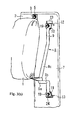
FIG. 2 is a sectional view taken along line II—II of FIG. 1.
FIG. 3 is a perspective view showing a deployment behavior of the curtain airbag.
FIG. 4 is a perspective view of the vicinity of the upper part of a guide member for a curtain airbag according to another embodiment of the present invention.
FIG. 5 is a perspective view of another embodiment.
FIG. 6 is a perspective view of still another embodiment.
DETAILED DESCRIPTION
As shown in FIG. 1, a curtain airbag 1 is arranged along a roof side (a boundary between the ceiling and the side of the compartment) 2 of a vehicle in a longitudinally-folded long thin state. The curtain airbag 1 is inflated by a gas from an inflator (not shown) in the event of a side impact or rollover of the vehicle, and is deployed downward relative to the vehicle along the side structure of the compartment such as a door and a pillar. The curtain airbag 1 has a tab 3 at the upper edge, wherein a bolt 5 (see FIG. 3) is inserted into a bolt insertion hole 4 of the tab 3, and is in turn screwed into a female screw hole 6 of the roof side 2, thereby fixing the curtain airbag 1 to the roof side 2.
The C pillar 7 of the vehicle has a guide member 8 for guiding the rear end of the curtain airbag 1 along the C pillar 7 when the curtain airbag 1 is inflated downward relative to the vehicle body and along the C pillar 7. The guide member 8 includes a rod-shaped guide 9 extending vertically relative to the vehicle body and along the C pillar 7, an upper fixing section 10 and a lower fixing section 11 for fixing the upper and lower ends of the guide 9 to the C pillar 7, respectively, and temporarily tacking sections 12 and 13 for temporarily tacking or connecting the upper and lower fixing sections 10 and 11 to the C pillar 7, respectively, when mounting the guide member 8 to the C pillar 7.
The curtain airbag 1 has a loop-like connecting band 14 in the vicinity of the lower corner at the rear end thereof. The connecting band 14 is hooked around the guide 9, so that the rear end of the curtain airbag 1 is connected to the guide member 8.
The guide 9 may be formed of a pipe member. The lower part of the guide 9 is bent in substantially a crank shape, thus forming a mooring section 9 a for the connecting band 14 at a generally L-shaped corner formed by an upper section 9 c and a substantially horizontal section 9 b of the guide. The horizontal section 9 b that connects with the mooring section 9 a works as a stopper for preventing the movement of the connecting band 14 downwardly from the mooring section 9 a.
The guide 9 has, at the upper and lower ends, leg- shaped sections 15 and 16 for separating the entire guide 9 from the outer surface of the C pillar 7. The leg- shaped sections 15 and 16 are formed such that the upper and lower ends of the guide 9 are bent in substantially a crank shape toward the C pillar 7. The upper and lower fixing section 10 and 11 connect with the ends of the leg- shaped sections 15 and 16, respectively.
The guide member 8 is fixed to the C pillar 7 such that bolts 19 are inserted into bolt insertion holes 17 and 18 (see FIG. 1) formed in the fixing sections 10 and 11, and are then screwed into female screw holes 20 of the C pillar 7, respectively.
The temporarily tacking sections 12 and 13 extend in the extending direction and the intersecting direction of the guide 9 so as to be inserted into the C pillar 7 through the surface at which the upper and lower fixing sections 10 and 11 overlap the C pillar 7, as shown in FIG. 2. The C pillar 7 has temporarily-tacking- section insertion openings 23 and 24 that correspond to the temporarily tacking sections 12 and 13. The upper temporarily tacking section 12 has a hook-shaped section 25 at the end, which is hooked to the lower edge of the opening 23.
In the embodiment, the hook-shaped section 25 is shaped such that the end of the upper temporarily tacking section 12 is bent downward.
The guide member 8 with such a structure can be temporarily tacked to the C pillar 7 such that the upper and lower temporarily tacking sections 12 and 13 are inserted into the corresponding temporarily-tacking- section insertion openings 23 and 24 for engagement. Therefore, there is no need to hold the guide member 8 by hand during the work such as bolting, thus remarkably simplifying installation work.
The hook-shaped section 25 provided at the end of the upper temporarily tacking section 12 is hooked to the lower edge of the opening 23. Therefore, even if a tool comes into contact with the guide member 8 during the work, the guide member 8 does not drop off the C pillar 7.
Since the temporarily tacking sections 12 and 13 are provided at the upper end and the lower end of the guide member 8, respectively, the guide member 8 is not rotated together with the bolts 19 even if the guide member 8 is not held by hand when the bolts 19 are inserted into the respective bolt insertion holes 17 and 18 of the upper and lower fixing sections 10 and 11 and are then screwed into the female screw holes 20 of the C pillar 7.
The guide member 8 mounted to the C pillar 7 guides the connecting band 14 downward when the curtain airbag 1 is inflated. The guide member 8 is arranged such that an upper section 9 c above the mooring section 9 a angles toward the rear of the vehicle as the upper section increases in height. Accordingly, the connecting band 14 that is the rear end of the curtain airbag 1 is prevented from returning upward when the curtain airbag 1 is guided by the guide member 8 to inflate downward relative to the vehicle body.
When inflated, the curtain airbag 1 decreases in longitudinal length by tension applied to the outer surface and the rear end is pulled forward. As shown in FIG. 3(b), when inflation has been completed, the connecting band 14 cannot move upward and backward along the guide 9, being held at the mooring section 9 a.
While in one embodiment of the present invention, the upper or lower part of the fixing sections 10 and 11 are bent toward the C pillar 7 to form the plate-like temporarily tacking sections 12 and 13, respectively, the shape and the forming method of the temporarily tacking sections is not limited to that configuration. For example, the temporarily tacking sections may be formed such that pins or projections are attached to the surfaces of the fixing sections 10 and 11 which overlap with the C pillar 7. These pins or projections may be welded onto the fixing sections. Also, the fixing sections may include an adhesive coating on the surface that contacts the C pillar in order to fix the guide pillar in place during installation.
As shown in FIG. 1, the temporarily tacking sections 12 and 13 and the guide member 8 are integrally formed. However, these components may also be formed as separate members. FIG. 4 shows an example in which each temporarily tacking section and the guide member are separately constructed. FIG. 4 is a perspective view of the vicinity of the upper part of a guide member for a curtain airbag according to another embodiment of the present invention.
A guide member 8A of FIG. 4 has a temporarily tacking member 30 at the vicinity of the upper end of the guide 9 (at the vicinity of the boundary with the leg-shaped section 15), which is constructed separately from the guide member 8A. The temporarily tacking member 30 includes a substantially-C-shaped clip 31 which is elastically in contact along the outer periphery of the guide 9 so as to hold the guide 9, a pair of extending pieces 32 and 32 which extends outward from the circumferential opposite ends of the clip 31, and a projecting temporarily tacking section 33 which extends from the side of one extending piece 32 in a direction that intersects the extending direction of the guide 9.
A similar temporarily tacking member 30 may also be attached to the vicinity of the lower end of the guide 9 (at vicinity of the boundary with the leg-shaped section 16), which is not shown. The C pillar has openings in which the temporarily tacking sections 33 of the temporarily tacking member 30 can be fitted.
Other structures of the guide member 8A are the same as those of the guide member 8 of FIGS. 1 to 3 except that the guide member 8 does not have the temporarily tacking sections 12 and 13 at the upper and lower fixing sections 10 and 11, respectively. In FIG. 4, the same reference numerals as those of FIGS. 1 to 3 denote the same elements.
When the guide member 8A with such a structure is mounted to a C pillar (not shown), first, the clip 31 is elastically increased in diameter so as to separate both the extending pieces 32 and 32 of the temporarily tacking member 30 from each other, and the guide 9 is in turn fitted to the inner periphery of the clip 31 from between the extending pieces 32 and 32, thereby attaching the temporarily tacking members 30 to the vicinities of the upper end and the lower end of the guide 9.
Then, each temporarily tacking section 33 of the temporarily tacking member 30 is fitted to the corresponding opening (not shown) of the C pillar; thereby the guide member 8A is tacked to the C pillar; and in this state, the fixing sections 10 and 11 are fixed with bolts, so that the guide member 8A is secured to the C pillar.
Accordingly, even for the guide member 8A, there is no need to hold the guide member 8A by hand during bolting work, as for the guide member 8, and thus the guide member 8A can be mounted to the C pillar by a vary simple operation. Also, when the fixing sections 10 and 11 are fixed with bolts, the guide member 8A does not rotate with the bolts, having greatly high wording efficiency.
In the embodiment of FIG. 4, the temporarily tacking section 33 is a plate-like projection that linearly extends from the extending piece 32. However, it is also possible to provide a hook-shaped section at the end of the temporarily tacking section 33, in a manner similar to the temporarily tacking section 12 of the guide member 8, thereby ensuring to prevent the temporarily tacking section 33 from coming out of the opening during the temporal tacking, that is, the guide member 8A from dropping off the C pillar.
In the embodiment of FIGS. 1 to 3, the mooring section 9 a is formed such that the guide 9 is bent so that the lower section leans forward (near the curtain airbag 1) from the middle to the lower end longitudinally; however, the structure of the mooring section is not limited to that.
Other embodiments of the mooring section will be described hereinafter with reference to FIGS. 5 and 6. FIGS. 5 and 6 are perspective views of the vicinities of the C pillars to which guide members 8B and 8B′ are mounted, respectively.
The guide member 8B of FIG. 5 also includes a rod-like guide 9B that extends vertically relative to the vehicle body along the C pillar 7, and the upper and lower fixing sections 10 and 11 for fixing the upper and lower ends of the guide 9B to the C pillar 7, respectively, and the temporarily tacking sections 12 and 13 for tacking both the upper and lower fixing sections 10 and 11 to the C pillar 7, respectively, when the guide member 8B is mounted to the C pillar 7. The rear end of the curtain airbag 1 is connected to the guide member 8B such that the loop-like connecting band 14 attached to the vicinity of the lower corner of the rear end is hooked around the guide 9B.
For the guide member 8B, a mooring section 40 is formed such that the lower part of the guide 9B which is substantially as high as the connecting band 14 of the curtain airbag 1 at the completion of inflation is bent forward (toward the curtain airbag 1) to form a loop.
Other structures of the guide member 8B are the same as those of the guide member 8 of FIGS. 1 to 3, wherein in FIG. 5, the same reference numerals as those of FIGS. 1 to 3 denote the same elements.
For the guide member 8B with such a structure, as the curtain airbag 1 is inflated to be deployed downward, the connecting band 14 is moved downward along the guide 9B, and when the curtain airbag 1 is inflated to substantially a maximum size, the connecting band 14 enters the mooring section 40. When the curtain airbag 1 has been fully inflated, the rear end of the curtain airbag 1 is pulled forward by tension applied to the outer surface, and also the connecting band 14 is pulled forward, thus being unable to come out from the mooring section 40. Accordingly, the rear end of the curtain airbag 1 is prevented from returning upward along the guide 9B.
A mooring section 41 of a guide member 8B′ of FIG. 6 is formed such that the mooring section 40 of the guide member 8B of FIG. 5 is made of a radially plastically deformable material. Other structures are the same and the same reference numerals denote the same elements. For the guide member 8B′, when the connecting band 14 enters the mooring section 41 as the curtain airbag 1 is deployed downward, and thereafter, the tension from the curtain airbag 1 is applied to the mooring section 41 through the connecting band 14, the mooring section 41 is pulled forward to be plastically deformed. Accordingly, the connecting band 14 is caught and secured by the mooring section 41 to prevent the rear end of the curtain airbag 1 from returning upward more reliably.
The embodiments described above are examples of the invention and the invention is not limited to the embodiments. For example, while the embodiments are constructed such that the C pillar 7 includes the guide member 8 to guide the rear end of the curtain airbag 1 downward relative to the vehicle body and along the C pillar 7 when the curtain airbag 1 is inflated. In the invention, however, the guide member may be provided to a B pillar or a D pillar. Alternatively, the guide member may be arranged at an A pillar to guide the front end of the curtain airbag.
As described in detail, according to the invention, there is provided a guide member for a curtain airbag which has remarkably high vehicle-installation efficiency. Also, according to the invention, it is also possible to prevent the end of the inflated curtain airbag from returning upward.
The priority application, Japanese Patent Application, Number 2002-212693, filed Jul. 22, 2002 is incorporated by reference herein in its entirety.
Given the disclosure of the present invention, one versed in the art would appreciate that there may be other embodiments and modifications within the scope and spirit of the invention. Accordingly, all modifications attainable by one versed in the art from the present disclosure within the scope and spirit of the present invention are to be included as further embodiments of the present invention. The scope of the present invention is to be defined as set forth in the following claims.

Claims (14)

1. A guide member for guiding a curtain airbag which is deployed downward along a side structure of a compartment of a vehicle, wherein the guide member extends vertically and is mounted to a pillar of the vehicle, wherein the guide member includes:
a mooring section formed by a bend or curved section of the guide member so as to prevent the ends of a deployed curtain airbag from returning upward;
an upper section extending upward from the mooring section and slanting toward the rear of the vehicle as the upper section extends upwardly; and
a vertical portion extending upward from the upper section.
2. The guide member of claim 1, further comprising a section that is configured to be temporarily connected to the vehicle prior to permanent installation of the guide member in the vehicle.
3. The guide member of claim 2, wherein the guide member is a pipe.
4. The guide member of claim 2, further comprising a section of the guide member that is configured to be permanently connected to the vehicle during installation of the guide member.
5. The guide member of claim 2, wherein the section of the guide member that is configured to be temporarily connected to the vehicle includes a projection that is configured to extend through openings in a vehicle pillar.
6. The guide member of claim 3, wherein the section of the guide member that is configured to be permanently connected to the vehicle during installation of the guide member includes openings for fasteners to pass through.
7. The guide member of claim 5, wherein the projection is hook shaped.
8. The guide member of claim 1, wherein the mooring section includes a looped section of the guide member.
9. The guide member of claim 1, wherein the mooring section includes a section of the guide member that is bent at least ninety degrees.
10. The guide member of claim 1, wherein each of an upper part and a lower part of the guide member includes a temporary tacking section for tacking the guide member to the pillar.
11. The guide member of claim 10, wherein the temporary tacking section extends in a direction generally perpendicular to the longitudinal direction of the guide member.
12. The guide member of claim 1, further comprising a leg shaped section extending toward the pillar for separating the vertical portion of the guide member from the pillar.
13. The guide member of claim 12, wherein the leg shaped section includes a curved portion for integrally connecting to the vertical portion.
14. The guide member of claim 13, wherein the leg shaped section is connected to an upper fixing portion for permanently connecting the guide member to the vehicle.
US10/620,450 2002-07-22 2003-07-17 Guide member for curtain airbag Expired - Fee Related US6896288B2 (en)

Applications Claiming Priority (2)

Application Number Priority Date Filing Date Title
JP2002-212693 2002-07-22
JP2002212693A JP4045884B2 (en) 2002-07-22 2002-07-22 Curtain airbag guide member and curtain airbag device

Publications (2)

Publication Number Publication Date
US20040012174A1 US20040012174A1 (en) 2004-01-22
US6896288B2 true US6896288B2 (en) 2005-05-24

Family

ID=29997215

Family Applications (1)

Application Number Title Priority Date Filing Date
US10/620,450 Expired - Fee Related US6896288B2 (en) 2002-07-22 2003-07-17 Guide member for curtain airbag

Country Status (4)

Country Link
US (1) US6896288B2 (en)
EP (2) EP1683688A3 (en)
JP (1) JP4045884B2 (en)
CN (1) CN100391763C (en)

Cited By (19)

* Cited by examiner, † Cited by third party
Publication number Priority date Publication date Assignee Title
US20030080541A1 (en) * 2001-10-30 2003-05-01 Kalandek Bruce A. Side impact or curtain air bag with position enhancing or locating mechanism
US20040178608A1 (en) * 2003-03-13 2004-09-16 Takata Corporation Curtain airbag system and guide mechanism thereof
US20040232663A1 (en) * 2003-05-19 2004-11-25 Takata Corporation Externally developed airbag device
US20050046159A1 (en) * 2003-09-01 2005-03-03 Takata Corporation Curtain airbag apparatus
US20050121885A1 (en) * 2003-12-05 2005-06-09 Elesys North America, Inc. Vehicle occupant sensing system
US20050134030A1 (en) * 2003-12-19 2005-06-23 Takata Corporation Guide unit for guiding curtain airbag and curtain airbag device
US20050134027A1 (en) * 2003-12-19 2005-06-23 Takata Corporation Guide unit for guiding curtain airbag and curtain airbag device
US20050179238A1 (en) * 2004-02-16 2005-08-18 Key Safety Systems, Inc. Attachment of a curtain airbag assembly to a vehicle
US20060097493A1 (en) * 2004-11-05 2006-05-11 Takata Corporation Curtain airbag device
US20070063490A1 (en) * 2005-09-20 2007-03-22 Takata Corporation Mounting structure for curtain airbag
US20070241542A1 (en) * 2006-04-18 2007-10-18 Mark Wallace Air Bag Deployment Ramp
US20080012271A1 (en) * 2006-06-29 2008-01-17 Takata-Petri Ag Side airbag
US20080111354A1 (en) * 2006-11-10 2008-05-15 Seung Soo Ryu Apparatus for guiding deployment of curtain airbag for vehicle
US8967661B2 (en) 2013-05-23 2015-03-03 Nissan North America, Inc. Vehicle body structure
US9333934B2 (en) 2014-06-13 2016-05-10 Nissan North America, Inc. Vehicle body structure
US20210101556A1 (en) * 2019-10-02 2021-04-08 Ford Global Technologies, Llc Vehicle airbag
US11135992B2 (en) 2020-01-23 2021-10-05 Ford Global Technologies, Llc Vehicle roof airbag
US20220306032A1 (en) * 2019-07-01 2022-09-29 Autoliv Development Ab Safety airbag assembly
US20230021237A1 (en) * 2021-07-14 2023-01-19 Hyundai Motor Company Curtain airbag apparatus for vehicle

Families Citing this family (16)

* Cited by examiner, † Cited by third party
Publication number Priority date Publication date Assignee Title
US6964431B2 (en) * 2002-09-30 2005-11-15 Tk Holdings, Inc. Loop cord slide device for airbag
JP2006008060A (en) * 2004-06-29 2006-01-12 Takata Corp Curtain airbag device
DE102004041930B4 (en) * 2004-08-30 2015-04-09 Trw Automotive Gmbh Airbag module with deployment aid
JP4622621B2 (en) * 2005-03-28 2011-02-02 マツダ株式会社 Curtain airbag device
JP4622620B2 (en) * 2005-03-28 2011-02-02 マツダ株式会社 Curtain airbag device
DE102005028505A1 (en) 2005-06-17 2007-04-12 GM Global Technology Operations, Inc., Detroit Safety arrangement and trim part for the interior of a motor vehicle
JP4923743B2 (en) 2005-08-23 2012-04-25 マツダ株式会社 Curtain airbag device
US8451398B2 (en) 2006-02-16 2013-05-28 Panasonic Corporation Light source device and liquid crystal display device using such light source device
JP4710747B2 (en) * 2006-07-26 2011-06-29 マツダ株式会社 Curtain airbag device
JP2008037245A (en) * 2006-08-04 2008-02-21 Mazda Motor Corp Curtain air bag device
JP4830706B2 (en) * 2006-08-04 2011-12-07 マツダ株式会社 Curtain airbag device
JP2011213300A (en) * 2010-04-01 2011-10-27 Nippon Plast Co Ltd Airbag device
GB201012753D0 (en) 2010-07-29 2010-09-15 Ford Global Tech Llc A curtain airbag for a motor vehicle
EP3473500B1 (en) * 2015-03-05 2020-10-14 Autoliv Development AB Installation structure of curtain airbag
KR102461508B1 (en) * 2017-12-08 2022-11-02 현대자동차주식회사 Air bag device for viehicle
US11702029B1 (en) 2021-03-26 2023-07-18 Apple Inc. Deployable restraints with tensioning mechanisms

Citations (10)

* Cited by examiner, † Cited by third party
Publication number Priority date Publication date Assignee Title
US4909541A (en) * 1987-11-06 1990-03-20 Nippon Seiko Kabushiki Kaisha Adjustable shoulder anchor mechanism
EP0642957A2 (en) 1993-09-10 1995-03-15 R. Schmidt Gmbh Height adjustable return loop fitting for safety belts
US5547222A (en) * 1994-01-28 1996-08-20 R. Schmidt Gmbh Safety belt system for a vehicle
US5951046A (en) 1997-01-31 1999-09-14 Suzuki Motor Corporation Construction for attaching a seat belt adjuster
EP0955213A1 (en) 1998-05-08 1999-11-10 Bayerische Motoren Werke Aktiengesellschaft, Patentabteilung AJ-3 Inflatable head protection system for the side region of a vehicle
WO2001032474A2 (en) 1999-11-04 2001-05-10 Breed Automotive Technology, Inc. Side airbag curtain module
US6237938B1 (en) 1999-09-01 2001-05-29 Trw Vehicle Safety Systems Inc. Inflatable curtain with anchor device
US6454296B1 (en) 2000-11-22 2002-09-24 Delphi Technologies, Inc. Side air bag for roll-over restraint
US20030080541A1 (en) * 2001-10-30 2003-05-01 Kalandek Bruce A. Side impact or curtain air bag with position enhancing or locating mechanism
US6733035B2 (en) 2002-03-05 2004-05-11 Delphi Technologies, Inc. Side curtain air bag assembly

Family Cites Families (4)

* Cited by examiner, † Cited by third party
Publication number Priority date Publication date Assignee Title
GB2333076B (en) * 1995-02-20 1999-08-25 Autoliv Dev Improvements in or relating to a safety device
JPH09249089A (en) * 1996-03-15 1997-09-22 Tokai Rika Co Ltd Air bag device
JP3707331B2 (en) * 2000-02-07 2005-10-19 いすゞ自動車株式会社 Curtain airbag compatible headlining support construction
JP2001260796A (en) * 2000-03-23 2001-09-26 Takata Corp Automobile occupant head crash protection device

Patent Citations (11)

* Cited by examiner, † Cited by third party
Publication number Priority date Publication date Assignee Title
US4909541A (en) * 1987-11-06 1990-03-20 Nippon Seiko Kabushiki Kaisha Adjustable shoulder anchor mechanism
EP0642957A2 (en) 1993-09-10 1995-03-15 R. Schmidt Gmbh Height adjustable return loop fitting for safety belts
US5547222A (en) * 1994-01-28 1996-08-20 R. Schmidt Gmbh Safety belt system for a vehicle
US5951046A (en) 1997-01-31 1999-09-14 Suzuki Motor Corporation Construction for attaching a seat belt adjuster
EP0955213A1 (en) 1998-05-08 1999-11-10 Bayerische Motoren Werke Aktiengesellschaft, Patentabteilung AJ-3 Inflatable head protection system for the side region of a vehicle
US6237938B1 (en) 1999-09-01 2001-05-29 Trw Vehicle Safety Systems Inc. Inflatable curtain with anchor device
WO2001032474A2 (en) 1999-11-04 2001-05-10 Breed Automotive Technology, Inc. Side airbag curtain module
US6412810B1 (en) 1999-11-04 2002-07-02 Breed Automotivetechnology, Inc. Inflatable side air bag curtain module
US6454296B1 (en) 2000-11-22 2002-09-24 Delphi Technologies, Inc. Side air bag for roll-over restraint
US20030080541A1 (en) * 2001-10-30 2003-05-01 Kalandek Bruce A. Side impact or curtain air bag with position enhancing or locating mechanism
US6733035B2 (en) 2002-03-05 2004-05-11 Delphi Technologies, Inc. Side curtain air bag assembly

Cited By (32)

* Cited by examiner, † Cited by third party
Publication number Priority date Publication date Assignee Title
US7044500B2 (en) * 2001-10-30 2006-05-16 Key Safety Systems, Inc. Side impact or curtain air bag with position enhancing or locating mechanism
US20030080541A1 (en) * 2001-10-30 2003-05-01 Kalandek Bruce A. Side impact or curtain air bag with position enhancing or locating mechanism
US20040178608A1 (en) * 2003-03-13 2004-09-16 Takata Corporation Curtain airbag system and guide mechanism thereof
US7219921B2 (en) * 2003-03-13 2007-05-22 Takata Corporation Curtain airbag system and guide mechanism thereof
US20040232663A1 (en) * 2003-05-19 2004-11-25 Takata Corporation Externally developed airbag device
US7174986B2 (en) * 2003-05-19 2007-02-13 Takata Corporation Externally developed airbag device
US20050046159A1 (en) * 2003-09-01 2005-03-03 Takata Corporation Curtain airbag apparatus
US20050121885A1 (en) * 2003-12-05 2005-06-09 Elesys North America, Inc. Vehicle occupant sensing system
US20050134027A1 (en) * 2003-12-19 2005-06-23 Takata Corporation Guide unit for guiding curtain airbag and curtain airbag device
US20050134030A1 (en) * 2003-12-19 2005-06-23 Takata Corporation Guide unit for guiding curtain airbag and curtain airbag device
US7273228B2 (en) * 2003-12-19 2007-09-25 Takata Corporation Guide unit for guiding curtain airbag and curtain airbag device
US7338071B2 (en) * 2003-12-19 2008-03-04 Takata Corporation Guide unit for guiding curtain airbag and curtain airbag device
US20050179238A1 (en) * 2004-02-16 2005-08-18 Key Safety Systems, Inc. Attachment of a curtain airbag assembly to a vehicle
US7303206B2 (en) * 2004-02-16 2007-12-04 Key Safety Systems, Inc. Attachment of a curtain airbag assembly to a vehicle
US20060097493A1 (en) * 2004-11-05 2006-05-11 Takata Corporation Curtain airbag device
US7347447B2 (en) * 2004-11-05 2008-03-25 Takata Corporation Curtain airbag device
US20070063490A1 (en) * 2005-09-20 2007-03-22 Takata Corporation Mounting structure for curtain airbag
US7780187B2 (en) * 2005-09-20 2010-08-24 Takata Corporation Mounting structure for curtain airbag
US20070241542A1 (en) * 2006-04-18 2007-10-18 Mark Wallace Air Bag Deployment Ramp
US20080012271A1 (en) * 2006-06-29 2008-01-17 Takata-Petri Ag Side airbag
US7712766B2 (en) * 2006-06-29 2010-05-11 Takata-Petri Ag Side airbag
US20080111354A1 (en) * 2006-11-10 2008-05-15 Seung Soo Ryu Apparatus for guiding deployment of curtain airbag for vehicle
US8967661B2 (en) 2013-05-23 2015-03-03 Nissan North America, Inc. Vehicle body structure
US9321422B2 (en) 2013-05-23 2016-04-26 Nissan North America, Inc. Vehicle body structure
US9333934B2 (en) 2014-06-13 2016-05-10 Nissan North America, Inc. Vehicle body structure
US20220306032A1 (en) * 2019-07-01 2022-09-29 Autoliv Development Ab Safety airbag assembly
US11766979B2 (en) * 2019-07-01 2023-09-26 Autoliv Development Ab Safety airbag assembly with connecting member
US20210101556A1 (en) * 2019-10-02 2021-04-08 Ford Global Technologies, Llc Vehicle airbag
US11148631B2 (en) * 2019-10-02 2021-10-19 Ford Global Technologies, Llc Vehicle airbag
US11135992B2 (en) 2020-01-23 2021-10-05 Ford Global Technologies, Llc Vehicle roof airbag
US20230021237A1 (en) * 2021-07-14 2023-01-19 Hyundai Motor Company Curtain airbag apparatus for vehicle
US11745692B2 (en) * 2021-07-14 2023-09-05 Hyundai Motor Company Curtain airbag apparatus for vehicle

Also Published As

Publication number Publication date
EP1683688A2 (en) 2006-07-26
JP2004051016A (en) 2004-02-19
CN100391763C (en) 2008-06-04
JP4045884B2 (en) 2008-02-13
CN1482028A (en) 2004-03-17
US20040012174A1 (en) 2004-01-22
EP1683688A3 (en) 2009-07-15
EP1384632A1 (en) 2004-01-28

Similar Documents

Publication Publication Date Title
US6896288B2 (en) Guide member for curtain airbag
US7290795B2 (en) Garnish clip for curtain shield airbag
US7216891B2 (en) Fastening device for curtain airbag tether
US6254123B1 (en) Mounting structure for use with a head-protecting airbag body
US7338068B2 (en) Garnish clip for curtain shield airbag
JP4619914B2 (en) Vehicle interior parts
US7374200B2 (en) Head protecting airbag device
US7780187B2 (en) Mounting structure for curtain airbag
US7210886B2 (en) Fastener for curtain airbag
US6070902A (en) Vehicle interior headliner system
US9663056B2 (en) Pillar garnish
US7871103B2 (en) Interior trim article-mounting structure of vehicle equipped with head protection airbag apparatus
KR100857369B1 (en) Curtain air bag install structure
JP5034455B2 (en) Interior structure of a vehicle equipped with a curtain airbag device
US20090152838A1 (en) Airbag inflator device and method of installation
US7338071B2 (en) Guide unit for guiding curtain airbag and curtain airbag device
US20050046159A1 (en) Curtain airbag apparatus
US7309078B2 (en) Vehicle with curtain air bag
KR101090830B1 (en) Curtain airbag module
JP2010168044A (en) Vehicle interior member
JP4134882B2 (en) Curtain airbag device
KR20230015720A (en) Tether clip and pillar connection structure provided with the same
JP3474109B2 (en) Head protection airbag bag fixing structure
JP4134883B2 (en) Curtain airbag device
JP6272702B2 (en) Mounting structure for vehicle pad member

Legal Events

Date Code Title Description
AS Assignment

Owner name: TAKATA CORPORATION, JAPAN

Free format text: ASSIGNMENT OF ASSIGNORS INTEREST;ASSIGNORS:TANAKA, TADASHI;KUMAGAI, MASAYOSHI;REEL/FRAME:014297/0440

Effective date: 20030610

FEPP Fee payment procedure

Free format text: PAYOR NUMBER ASSIGNED (ORIGINAL EVENT CODE: ASPN); ENTITY STATUS OF PATENT OWNER: LARGE ENTITY

CC Certificate of correction
FPAY Fee payment

Year of fee payment: 4

REMI Maintenance fee reminder mailed
LAPS Lapse for failure to pay maintenance fees
STCH Information on status: patent discontinuation

Free format text: PATENT EXPIRED DUE TO NONPAYMENT OF MAINTENANCE FEES UNDER 37 CFR 1.362

FP Lapsed due to failure to pay maintenance fee

Effective date: 20130524