US6889875B2 - Taper well meter dose pump - Google Patents
Taper well meter dose pump Download PDFInfo
- Publication number
- US6889875B2 US6889875B2 US10/197,627 US19762702A US6889875B2 US 6889875 B2 US6889875 B2 US 6889875B2 US 19762702 A US19762702 A US 19762702A US 6889875 B2 US6889875 B2 US 6889875B2
- Authority
- US
- United States
- Prior art keywords
- dip tube
- semi
- solid substance
- well
- chamber
- Prior art date
- Legal status (The legal status is an assumption and is not a legal conclusion. Google has not performed a legal analysis and makes no representation as to the accuracy of the status listed.)
- Expired - Fee Related, expires
Links
- 230000007246 mechanism Effects 0.000 claims abstract description 28
- 239000007787 solid Substances 0.000 claims description 56
- 239000000126 substance Substances 0.000 claims description 54
- 238000000605 extraction Methods 0.000 claims description 9
- 238000000518 rheometry Methods 0.000 claims description 3
- 239000012530 fluid Substances 0.000 abstract description 31
- 238000005086 pumping Methods 0.000 description 5
- 239000011346 highly viscous material Substances 0.000 description 4
- 244000273618 Sphenoclea zeylanica Species 0.000 description 3
- 230000008901 benefit Effects 0.000 description 3
- 238000012986 modification Methods 0.000 description 3
- 230000004048 modification Effects 0.000 description 3
- 239000000463 material Substances 0.000 description 2
- 238000002360 preparation method Methods 0.000 description 2
- 238000013022 venting Methods 0.000 description 2
- 230000009471 action Effects 0.000 description 1
- 239000000853 adhesive Substances 0.000 description 1
- 230000001070 adhesive effect Effects 0.000 description 1
- 238000013459 approach Methods 0.000 description 1
- 238000004891 communication Methods 0.000 description 1
- 230000001010 compromised effect Effects 0.000 description 1
- 239000002537 cosmetic Substances 0.000 description 1
- 239000006071 cream Substances 0.000 description 1
- 230000007423 decrease Effects 0.000 description 1
- 230000000994 depressogenic effect Effects 0.000 description 1
- 238000013461 design Methods 0.000 description 1
- 239000003292 glue Substances 0.000 description 1
- 239000007788 liquid Substances 0.000 description 1
- 238000004519 manufacturing process Methods 0.000 description 1
- 230000013011 mating Effects 0.000 description 1
- 239000002674 ointment Substances 0.000 description 1
- 230000004044 response Effects 0.000 description 1
- 230000000699 topical effect Effects 0.000 description 1
Images


Classifications
-
- B—PERFORMING OPERATIONS; TRANSPORTING
- B05—SPRAYING OR ATOMISING IN GENERAL; APPLYING FLUENT MATERIALS TO SURFACES, IN GENERAL
- B05B—SPRAYING APPARATUS; ATOMISING APPARATUS; NOZZLES
- B05B11/00—Single-unit hand-held apparatus in which flow of contents is produced by the muscular force of the operator at the moment of use
- B05B11/01—Single-unit hand-held apparatus in which flow of contents is produced by the muscular force of the operator at the moment of use characterised by the means producing the flow
- B05B11/02—Membranes or pistons acting on the contents inside the container, e.g. follower pistons
- B05B11/028—Pistons separating the content remaining in the container from the atmospheric air to compensate underpressure inside the container
Definitions
- the present invention relates generally to fluid dispensing devices and more particularly to metered-dose pump devices useful for dispensing high-viscosity semi-solid substances.
- Typical dispensing devices as shown therein include a substantially tubular hollow container body having a substantially circular cross section fitted with a finger-operable pump mechanism and a follower, or take-up, piston.
- the finger-operable pump includes a dip tube having an inlet at its end that provides the fluid to a pump chamber for discharge at a dispensing outlet.
- the follower piston slides toward the pump mechanism due to atmospheric pressure acting on the exterior surface of the piston. This action decreases the internal volume of the body by an amount equal to the volume of product discharged.
- the piston may be fully enclosed by the container body, in which case a vent is typically provided to ensure atmospheric pressure at the external surface of the piston.
- FIGS. 1 and 2 illustrate a dispenser configured with a typical follower piston 25 having a well 40 adapted to mate with the receiving end of a dispensing valve, or dip tube 35 , when the piston 25 reaches its uppermost position ( FIG. 2 , associated with a reduced content of product in the body).
- a typical follower piston 25 having a well 40 adapted to mate with the receiving end of a dispensing valve, or dip tube 35 , when the piston 25 reaches its uppermost position ( FIG. 2 , associated with a reduced content of product in the body).
- a dispensing valve or dip tube 35
- FIGS. 1 and 2 illustrate a dispenser configured with a typical follower piston 25 having a well 40 adapted to mate with the receiving end of a dispensing valve, or dip tube 35 , when the piston 25 reaches its uppermost position ( FIG. 2 , associated with a reduced content of product in the body).
- such a configuration works well for fluid or semi-solid preparations with very low viscosity.
- the pump mechanism may quit pumping or it may deliver inaccurate volume after a significant portion (e.g., about 70%) of the material has been depleted.
- the gap between the pumping tube and the walls of the piston well is generally too limited to allow slightly viscous to highly viscous material to flow freely into the pumping well.
- the volume delivered may be inaccurate and in some cases the pumping mechanism may not work.
- the present invention provides dispensing devices and systems that efficiently dispense fluid, particularly highly viscous substances, after a significant portion of the fluid has been dispensed.
- a dispensing device includes a follower piston coupled within a hollow body and a pump mechanism having a dip tube coupled at the other end of the body and defining a chamber for holding fluid therebetween.
- a well provided in the piston is generally larger in diameter than the dip tube to allow fluid, and particularly highly viscous fluid, in the chamber to flow down into the well as the dip tube enters the well to facilitate fluid removal after a significant portion of the fluid has already been removed.
- the well walls and dip tube end are substantially conical shaped with the well walls either substantially parallel to the dip tube end or having a greater angle relative to the axis of the dip tube.
- a metered-dose pump device for dispensing doses of a semi-solid substance.
- the device typically includes a substantially cylindrical body having a central axis and defining a chamber for housing the semi-solid substance, and a dispensing mechanism coupled to one end of the body, the mechanism including a dip tube having an end with an orifice extending into the chamber along the central axis for extracting the semi-solid substance from the chamber.
- the device also typically includes a piston slidably coupled within the other end of the body, wherein the piston slides with sealable contact within the body, wherein the piston includes a central well which is positioned in line with the central axis, the well having walls with a substantially conical shape and extending outwards from the bottom of the well relative to the central axis, and wherein the bottom of the well is substantially the same size as the orifice of the dip tube.
- the semi solid substance is able to flow down into the well around the end of the dip tube so as to facilitate extraction of the remaining semi-solid substance after a substantial portion of the semi-solid substance has already been extracted.
- a metered-dose pump device for dispensing controlled amounts of a semi-solid substance.
- the device typically includes a substantially cylindrical body having a central axis and defining a chamber for housing the semi-solid substance, and a dispensing mechanism coupled to one end of the body, the mechanism including a substantially cylindrical dip tube having an end with an orifice extending into the chamber along the central axis for extracting the semi-solid substance from the chamber.
- the device also typically includes a piston positioned at the other end of the body and within the body, wherein the piston slides with sealable contact within the body, wherein the piston includes a contact surface defining a boundary of the chamber in contact with the semi-solid substance, the surface having a central well which is positioned in line with the central axis, the well having walls extending outwards from the bottom of the well relative to the central axis with a substantially conical shape, and wherein the bottom of the well is substantially the same size as the orifice of the dip tube.
- the piston slides within the body toward the dispensing mechanism so that when a substantial portion of the semi-solid substance has been removed, the dip tube enters the well, and wherein the remaining semi-solid substance flows down into the well proximal the end of the dip tube so as to facilitate extraction of the remaining semi-solid substance.
- a metered-dose pump device for dispensing a semi-solid substance.
- the device typically includes a substantially cylindrical body having a central axis and defining a chamber for housing a semi-solid substance, and a dip tube having an end with an orifice extending into the chamber along the central axis.
- the device also typically includes a pump means, coupled to one end of the body and to the dip tube, for extracting a portion of the semi-solid substance from the chamber through the dip tube, and for providing the extracted semi-solid substance to a user, and a piston, slidably coupled within the other end of the body, wherein the piston slides with sealable contact within the body, wherein the piston includes a central well which is positioned in line with the axis, the well having walls with a substantially conical shape and extending outwards from the bottom of the well relative to the axis, and wherein the bottom of the well is substantially the same size as the orifice of the dip tube.
- the semi solid substance is able to flow down into the well around the end of the dip tube so as to facilitate extraction of the remaining semi-solid substance after a substantial portion of the semi-solid substance has already been extracted.
- FIGS. 1 and 2 illustrate a cross-sectional side view of a prior art dispensing device with the piston at its lowermost and uppermost positions, respectively;
- FIG. 3 illustrates a cross section of a portion of a dispensing device according to an embodiment of the present invention
- FIG. 3 show a side view of a portion of a follower piston according to an embodiment of the present invention
- FIG. 4 illustrates another embodiment of a well, including only a first well wall portion according to an embodiment of the present invention
- FIG. 5 shows a side view of a portion of a follower piston and a dip tube according to an embodiment of the present invention
- FIG. 6 shows a side view of a portion of a follower piston and a dip tube according to another embodiment of the present invention
- FIG. 7 illustrates another embodiment of the dip tube of FIG. 6 .
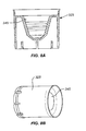
- FIGS. 8 a and 8 b illustrate a side view and an isometric view, respectively, of a follower piston according to another embodiment of the present invention.
- a dispensing device 10 includes a substantially cylindrical hollow body 15 and a pump mechanism 20 and a follower piston 25 defining a chamber 12 therebetween for holding the fluid product to be dispensed.
- FIGS. 1 and 2 are illustrative of a typical prior art dispensing device, and are used herein to describe general aspects and features of devices of the present invention. Specific implementations, embodiments and modifications according to the present invention will be described below with reference to FIGS. 3-7 .
- pump mechanism 20 is adapted to mate with body 15 as is well known, e.g., by snap-fit or screw-fit engagement to top portion 16 of body 15 , by glue or other adhesive, or using other suitable mating means.
- pump 20 includes an internal pumping mechanism that may be of any appropriate conventional or special non-venting design.
- a conventional, non-venting pump such as the pump illustrated in FIGS. 1 and 2 , has an interior chamber (not shown) which has a check valve at the lower end and in which is disposed a pressurizing piston (not shown).
- the pressurizing piston is arranged to cooperate with a hollow stem 22 which extends out through the top of the body of the pump and which is received within the pump actuator button 26 so as to provide egress to dispensing orifice 28 .
- the stem 22 and the piston within the pump body can move downwardly together in the pump chamber, but the hollow stem 22 can also move for some distance separately relative to the piston so as to establish communication through the hollow stem 22 between the pump chamber and the actuator button 26 .
- One or more springs (not shown in the figures), or other biasing mechanisms, act against the piston and/or stem 22 inside the pump body to bias the piston, stem 22 , and actuator button 26 upwardly to an elevated rest position when finger pressure is released.
- a receiving orifice 36 disposed at the end of the dip tube 35 provides for ingress of the product from chamber 12 into the internal pump chamber.
- product is dispensed from the pump 20 via dispensing orifice 28 , and when depressed, product is extracted from chamber 12 into pump 20 .
- a check valve e.g., a ball bearing, may be disposed within dip tube 35 proximal orifice 36 to prevent backflow of product into chamber 12 when actuator button 26 is pressed.
- An optional cap or cover 30 may be releasably mounted over pump mechanism 20 as shown.
- An optional bottom portion 44 is provided, which for embodiments including a vacuum-filled chamber 12 also includes a vent 42 to ensure atmospheric pressure at the external surface (e.g., bottom) of piston 25 .
- a lip seal 46 provides a seal at the contact perimeter between piston 25 and body 15 .
- FIG. 3 show a side view of a follower piston 125 according to an embodiment of the present invention.
- Piston 125 includes a well 140 defined by well walls 145 and well bottom 152 .
- a lip 146 provides a (slidable) seal with the body of the dispensing device.
- well 140 includes a second wall portion 145 ′ having an angle 151 , relative to axis 150 , that is greater than the angle formed by first portion 145 .
- FIG. 4 illustrates another embodiment of a well 140 , including only first well wall portion 145 , without a second well wall portion having a different angle relative to axis 150 .
- one or more passageways 147 , and/or one or more notches may be cut into or formed in piston 125 so as to provide one or more conduits or openings to facilitate fluid flow into well 140 from space 148 around the periphery of the top of piston 125 as piston 125 approaches pump mechanism 20 .
- FIG. 5 shows a side view of a portion of the follower piston 125 and a dip tube 135 according to an embodiment of the present invention.
- dip tube 135 includes side walls 138 that are substantially parallel to axis 150 (not shown).
- well 140 and dip tube 135 have substantially circular cross-sections (e.g., when viewed from above), although they may have oval or other cross-section geometries as desired.
- dip tube wall 138 and well wall 145 advantageously allows fluid, and particularly highly viscous fluid such as fluid having a viscosity greater than about 1,000 cps, and preferably greater than about 2,000 cps, or a non-newtonian rheology, to more freely and efficiently flow therebetween to reach the bottom 152 of well 140 so as to facilitate extraction via orifice 136 of dip tube 135 as tube 135 enters well 140 .
- Second dip tube wall portion 138 ′ is provided in some embodiments, for example, to allow for a larger circumference dip tube and improved fluid flow relative to well wall 145 ′ as dip tube 135 reaches the bottom of well 140 .
- FIG. 6 shows a side view of a portion of the follower piston 125 and a dip tube 135 according to another embodiment of the present invention.
- dip tube 135 includes walls 138 that are substantially parallel to well walls 145 .
- Dip tube 135 is sized and dimensioned relative to well 140 to provide annular space between dip tube walls 138 and well walls 145 sufficient to allow fluid, and particularly viscous and highly-viscous fluid to efficiently flow therebetween to the bottom 152 of well 140 as dip tube 135 enters well 140 .
- well 140 and dip tube 135 preferably have substantially circular cross-sections (e.g., when viewed from above) such as to form conical-shaped structures, although they may have oval or other cross-section geometries as desired
- the angle 151 between axis 150 and well walls 145 and/or tube walls 138 is preferably not greater than 30 degrees, but may be greater such as 40 degrees, 45 degrees or more. Additionally, the relative angle between the well walls 145 and axis 150 is preferably greater than or equal to the relative angle between the dip tube walls 138 and axis 150 .
- FIG. 7 illustrates additional features and embodiments of a dip tube similar to dip tube 135 of FIG. 6 .
- dip tube 235 includes one or more perforations 237 positioned proximal the bottom of the dip tube to facilitate extraction of fluid into the internal pump chamber (not shown).
- one or more slotted openings 239 are provided to facilitate fluid extraction. It should be understood that the number and dimensions of the perforations and/or slotted openings can be varied as desired for the particular application/fluid medium. It should also be appreciated that perforations and/or slotted openings are applicable to other dip tube configurations including, for example, the dip tube configuration as shown in FIG. 5 , wherein such openings and/or perforations would preferably be included in walls 138 ′.
- the dip tube configurations as shown in FIGS. 5 and 6 and used with the well configuration of FIG. 3 could also be used with the well configuration shown in FIG. 4 , wherein the dip tube is preferably geometrically configured and sized relative to the well walls to provide improved fluid flow as taught herein.
- the chamber 12 may be filled with fluid either under vacuum, or under atmospheric pressure and then vacuum pressured.
- FIGS. 8 a and 8 b illustrate a side view and an isometric view, respectively, of a follower piston 325 according to another embodiment of the present invention.
- follower piston 325 is similar in many respects to follower piston 125 of FIG. 3 .
- the walls 345 do not extend above the main body as shown, whereas walls 145 of piston 125 extend above the main body, e.g., above the circumference defined by lip 146 . It should be appreciated that other piston configurations may be implemented within the scope of the present invention.
Landscapes
- Reciprocating Pumps (AREA)
- Containers And Packaging Bodies Having A Special Means To Remove Contents (AREA)
- Closures For Containers (AREA)
Abstract
Description
Claims (29)
Priority Applications (1)
| Application Number | Priority Date | Filing Date | Title |
|---|---|---|---|
| US10/197,627 US6889875B2 (en) | 2002-06-04 | 2002-07-15 | Taper well meter dose pump |
Applications Claiming Priority (2)
| Application Number | Priority Date | Filing Date | Title |
|---|---|---|---|
| US38601402P | 2002-06-04 | 2002-06-04 | |
| US10/197,627 US6889875B2 (en) | 2002-06-04 | 2002-07-15 | Taper well meter dose pump |
Publications (2)
| Publication Number | Publication Date |
|---|---|
| US20030222105A1 US20030222105A1 (en) | 2003-12-04 |
| US6889875B2 true US6889875B2 (en) | 2005-05-10 |
Family
ID=29586378
Family Applications (1)
| Application Number | Title | Priority Date | Filing Date |
|---|---|---|---|
| US10/197,627 Expired - Fee Related US6889875B2 (en) | 2002-06-04 | 2002-07-15 | Taper well meter dose pump |
Country Status (1)
| Country | Link |
|---|---|
| US (1) | US6889875B2 (en) |
Cited By (1)
| Publication number | Priority date | Publication date | Assignee | Title |
|---|---|---|---|---|
| US20070084110A1 (en) * | 2004-05-06 | 2007-04-19 | Eric Rossignol | Closure Device For A Non-Vented Liquid Product Dispenser |
Families Citing this family (7)
| Publication number | Priority date | Publication date | Assignee | Title |
|---|---|---|---|---|
| US8980290B2 (en) | 2000-08-03 | 2015-03-17 | Antares Pharma Ipl Ag | Transdermal compositions for anticholinergic agents |
| ATE485837T1 (en) * | 2000-08-03 | 2010-11-15 | Antares Pharma Ipl Ag | COMPOSITION FOR TRANSDERMAL AND/OR TRANSMUCOSAL ADMINISTRATION OF ACTIVE INGREDIENTS WHICH GUARANTEES ADEQUATE THERAPEUTIC LEVELS |
| US7198801B2 (en) | 2000-08-03 | 2007-04-03 | Antares Pharma Ipl Ag | Formulations for transdermal or transmucosal application |
| ATE534373T1 (en) | 2003-10-10 | 2011-12-15 | Antares Pharma Ipl Ag | TRANSDERMAL PHARMACEUTICAL FORMULATION TO MINIMIZE RESIDUE ON THE SKIN |
| US7425340B2 (en) | 2004-05-07 | 2008-09-16 | Antares Pharma Ipl Ag | Permeation enhancing compositions for anticholinergic agents |
| US8067399B2 (en) | 2005-05-27 | 2011-11-29 | Antares Pharma Ipl Ag | Method and apparatus for transdermal or transmucosal application of testosterone |
| CN101426475A (en) | 2006-04-21 | 2009-05-06 | 安塔雷斯制药Ipl股份公司 | Methods of treating hot flashes with formulations for transdermal or transmucosal application |
Citations (3)
| Publication number | Priority date | Publication date | Assignee | Title |
|---|---|---|---|---|
| US5921438A (en) * | 1992-05-11 | 1999-07-13 | Yoshino Kogyosho Co., Ltd. | Laminated bottle and pump device therefor |
| US6375045B1 (en) * | 2000-03-30 | 2002-04-23 | Yonwoo Corporation | Airless type dispenser |
| US6418978B2 (en) * | 1998-01-08 | 2002-07-16 | L'oreal | Packaging and dispensing device including a vacuum-filled container, and a method of manufacture |
-
2002
- 2002-07-15 US US10/197,627 patent/US6889875B2/en not_active Expired - Fee Related
Patent Citations (3)
| Publication number | Priority date | Publication date | Assignee | Title |
|---|---|---|---|---|
| US5921438A (en) * | 1992-05-11 | 1999-07-13 | Yoshino Kogyosho Co., Ltd. | Laminated bottle and pump device therefor |
| US6418978B2 (en) * | 1998-01-08 | 2002-07-16 | L'oreal | Packaging and dispensing device including a vacuum-filled container, and a method of manufacture |
| US6375045B1 (en) * | 2000-03-30 | 2002-04-23 | Yonwoo Corporation | Airless type dispenser |
Cited By (2)
| Publication number | Priority date | Publication date | Assignee | Title |
|---|---|---|---|---|
| US20070084110A1 (en) * | 2004-05-06 | 2007-04-19 | Eric Rossignol | Closure Device For A Non-Vented Liquid Product Dispenser |
| US7694856B2 (en) * | 2004-05-06 | 2010-04-13 | Rexam Dispensing Smt | Closure device for a non-vented liquid product dispenser |
Also Published As
| Publication number | Publication date |
|---|---|
| US20030222105A1 (en) | 2003-12-04 |
Similar Documents
| Publication | Publication Date | Title |
|---|---|---|
| US9254954B2 (en) | Metering valve | |
| CN1210077C (en) | Medium dispenser | |
| JP5536961B2 (en) | Liquid container with vacuum pumping device | |
| US10138050B2 (en) | Dispensing valve incorporating a metering valve | |
| US20110240677A1 (en) | Airless double-piston double-action pump and cosmetics bottle dispensing device | |
| CN100464871C (en) | Manual metering pump and device for packaging and dispensing fluid or pasty products | |
| CN107626017B (en) | Liquid dropping device | |
| CZ153199A3 (en) | Pumping dosing apparatus | |
| KR102035727B1 (en) | Dispenser for liquid container | |
| CN103189146A (en) | Dosing hoods for containers | |
| CN101443128A (en) | Fluid product dispensing pump | |
| US6889875B2 (en) | Taper well meter dose pump | |
| JPS63200857A (en) | Pump dispenser for viscous product | |
| CN116547027A (en) | Device for delivering a dose of a mist of an ophthalmic liquid, and pump suitable for a device for delivering a dose of an ophthalmic liquid | |
| US12434900B2 (en) | Aerosol metering valve system and a container comprising an aerosol metering valve system | |
| EP2121462B1 (en) | Inlet for pump | |
| JP6682093B2 (en) | Drug dispenser with bacteria penetration prevention function | |
| JP2023529541A (en) | Actuator valve cartridges in various packaging | |
| KR20200071096A (en) | Fluid product distributor | |
| CN100564192C (en) | Metering valves and dispenser devices for dispensing liquids or powders | |
| AU2015218380B2 (en) | Dispensing valve incorporating a metering valve | |
| KR102306251B1 (en) | Container | |
| HU222174B1 (en) | Dispensing device for storing liquid and plastic materials and dispensing by means of pressure gas | |
| AU2381288A (en) | Container for liquids | |
| US7178701B2 (en) | Metering pump |
Legal Events
| Date | Code | Title | Description |
|---|---|---|---|
| AS | Assignment |
Owner name: CELLEGY PHARMACEUTICALS, INC., CALIFORNIA Free format text: ASSIGNMENT OF ASSIGNORS INTEREST;ASSIGNORS:LEE, CHARLES E.;LEE, J.C;REEL/FRAME:013369/0159 Effective date: 20020923 |
|
| AS | Assignment |
Owner name: STRAKAN INTERNATIONAL LIMITED, UNITED KINGDOM Free format text: SECURITY INTEREST;ASSIGNOR:CELLEGY PHARMACEUTICALS, INC.;REEL/FRAME:018338/0001 Effective date: 20060926 |
|
| AS | Assignment |
Owner name: STRAKAN INTERNATIONAL LIMITED, UNITED KINGDOM Free format text: ASSIGNMENT OF ASSIGNORS INTEREST;ASSIGNOR:CELLEGY PHARMACEUTICALS, INC.;REEL/FRAME:018934/0497 Effective date: 20061128 |
|
| AS | Assignment |
Owner name: CELLEGY PHARMACEUTICALS, INC., CALIFORNIA Free format text: MERGER;ASSIGNOR:CELLEGY PHARMACEUTICALS, INC.;REEL/FRAME:018942/0268 Effective date: 20040615 |
|
| AS | Assignment |
Owner name: CELLEGY PHARMACEUTICALS, INC., PENNSYLVANIA Free format text: TERMINATION AND RELEASE OF SECURITY INTEREST IN PATENTS;ASSIGNOR:STRAKAN INTERNATIONAL LIMITED;REEL/FRAME:019028/0368 Effective date: 20061128 |
|
| AS | Assignment |
Owner name: MORGAN STANLEY BANK INTERNATIONAL LIMITED, UNITED Free format text: PATENT SECURITY AGREEMENT;ASSIGNOR:STRAKAN INTERNATIONAL LIMITED;REEL/FRAME:019094/0323 Effective date: 20070327 |
|
| REMI | Maintenance fee reminder mailed | ||
| LAPS | Lapse for failure to pay maintenance fees | ||
| STCH | Information on status: patent discontinuation |
Free format text: PATENT EXPIRED DUE TO NONPAYMENT OF MAINTENANCE FEES UNDER 37 CFR 1.362 |
|
| FP | Lapsed due to failure to pay maintenance fee |
Effective date: 20090510 |
|
| AS | Assignment |
Owner name: STRAKAN INTERNATIONAL LIMITED, BERMUDA Free format text: RELEASE OF PATENT SECURITY AGREEMENT;ASSIGNOR:MORGAN STANLEY BANK INTERNATIONAL LIMITED, AS SECURITY TRUSTEE;REEL/FRAME:027212/0299 Effective date: 20111110 |