US6883555B1 - Device for producing a tubular belt band that can be turned inside out - Google Patents
Device for producing a tubular belt band that can be turned inside out Download PDFInfo
- Publication number
- US6883555B1 US6883555B1 US10/168,168 US16816802A US6883555B1 US 6883555 B1 US6883555 B1 US 6883555B1 US 16816802 A US16816802 A US 16816802A US 6883555 B1 US6883555 B1 US 6883555B1
- Authority
- US
- United States
- Prior art keywords
- belt bands
- belt
- power loom
- bands
- hem
- Prior art date
- Legal status (The legal status is an assumption and is not a legal conclusion. Google has not performed a legal analysis and makes no representation as to the accuracy of the status listed.)
- Expired - Lifetime
Links
Images


Classifications
-
- D—TEXTILES; PAPER
- D03—WEAVING
- D03D—WOVEN FABRICS; METHODS OF WEAVING; LOOMS
- D03D1/00—Woven fabrics designed to make specified articles
- D03D1/0005—Woven fabrics for safety belts
-
- D—TEXTILES; PAPER
- D03—WEAVING
- D03D—WOVEN FABRICS; METHODS OF WEAVING; LOOMS
- D03D11/00—Double or multi-ply fabrics not otherwise provided for
- D03D11/02—Fabrics formed with pockets, tubes, loops, folds, tucks or flaps
Definitions
- the invention pertains to a device for producing at least two tubular belt bands which can be turned inside-out.
- WO 98/51,845 describes a tubular band and a device for its production on a power loom.
- the power loom has a reed, the dents of which form a gap, which tapers down from the top toward the bottom.
- the reed can be moved up and down, as a result of which the warp threads arrive in areas where they are spread out to different degrees (areas of different density), so that a tubular band of varying width can be produced.
- the widening effect of the expanders can be controlled in synchrony with, and essentially in proportion to, the increase or decrease in the distance between the warp threads.
- tubular band be produced on a power loom as a wide, multiple-use fabric with a seam and that it then be cut into individual tubular bands by a thermal cutting device. Because of the considerable change in the density of the warp threads by the reed, however, there is considerable doubt that a usable wide fabric can be produced, since there is a considerable amount of additional compression and decompression between the adjacent tubular bands.
- the density of the warp threads changes in correspondence with the degree of spreading by the reed, which means that structure of the fabric is looser in the wider areas than in the narrower ones.
- the tubular band which is obtained has a relatively coarse structure, especially in the wider areas, and its strength is also limited correspondingly.
- a tubular fabric of this type is not suitable as a belt band nor as an inflatable auto safety belt, because such belt bands must absorb longitudinal forces, that is, forces which proceed in the restraining direction.
- the threads are neither parallel to each other nor straight, as a result of which longitudinal forces cannot be absorbed efficiently; on the contrary, they cause a change in the length and/or a deformation of the belt band.
- the hem of the tubular band is on the outside, which is not only unsightly but also dangerous because of its hard edge, which can cause injury.
- a woven belt band which is suitable as an inflatable belt band for auto safety belts is described in WO 99/40,247.
- the disadvantage here is that this fabric either must be woven as a round fabric or it must have two woven layers, which are connected to each other along at least one side by a woven hem.
- the belt band must be assembled to form several layers by a complicated process, not only to make it suitable as a belt band but also to hide the unsightly and dangerous hem.
- the task of the invention is to provide a device for producing a tubular belt band which can be turned inside out, this device making it possible to produce the belt band easily and efficiently.
- a device having a power loom with a shedding mechanism having a reed with parallel dents, a woof insertion device that extends over an entire width of the power loom, and a control unit for controlling the shedding mechanism.
- the power loom further includes an expander that extends over the entire width of the power loom.
- the expander has a smaller diameter in a tubular area than in a hem area in correspondence with the belt bands to be produced so that the clamping pressure of the expander is substantially constant over an entire width of the woven fabric web.
- the device further includes a thermal cutting device having cutting heads operative to cut out the belt bands in the hem area from the woven fabric web.
- the belt band is produced on a power loom with parallel dents and because the shape of the cavity is determined only by the production of the hem, it is simple to produce; and second, because the warp threads are exactly parallel to each other and thus do not undergo any change in length or position under load, a very strong and durable belt band is obtained.
- the expander which extends over the entire width of the fabric, has a smaller diameter in the area of the tubular band than it does in the area of the hem, which ensures that the fabric is clamped uniformly over its entire width and that the woven fabric web takes a smooth course with little or no distortion and thus that the fabric can be produced satisfactorily in spite of different thicknesses and densities of the weave.
- production is especially efficient because of the multiple use which is now possible; that is, at least two belt bands can be produced simultaneously in the woven web.
- the woven hem can be made to lie on the inside by reversing the inside and outside surfaces.
- the woven belt band thus obtained is not only visually attractive but also highly advantageous in use. Because the edge of the belt band is rounded, it looks attractive and is also convenient and safe to use. In particular, these positive properties make it suitable as an inflatable auto safety belt.
- the belt band is suitable for a wide variety of uses. For example, it is suitable for air or water bags and for air or water hoses. It is also suitable as strapping or as safety belt material for vehicles and is especially suitable for inflatable auto safety belts.
- FIG. 1 shows a cross section of a belt band turned inside out
- FIG. 2 shows a cross section of the belt band according to FIG. 1 before it has been turned inside out
- FIG. 3 shows the belt band of FIG. 2 with the arrangement of the threads made evident
- FIG. 4 shows another cross section of an inside-out belt band with cavity sections of different widths
- FIG. 5 shows a diagram of the belt band of FIG. 4 before it has been turned inside out
- FIG. 6 shows a cross section of the belt band of FIG. 5 along line VI—VI of FIG. 5 ;
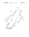
- FIG. 7 shows a schematic diagram of a side view of a power loom used for the production of the belt band
- FIG. 8 shows a top view of the power loom of FIG. 7 along line VIII—VIII of FIG. 7 ;
- FIG. 9 shows a partial cutaway schematic diagram of the expander of the power loom of FIG. 8 in detail, on a larger scale
- FIG. 10 shows a schematic diagram of the production of the belt band of FIG. 1 by cutting a wide fabric web into individual belt bands;
- FIG. 11 shows a schematic diagram of a first variant of the production of a belt band of FIGS. 4-6 by making straight cuts through a wide fabric web;
- FIG. 12 shows a second variant of the production of a belt band of FIGS. 4-6 by cutting through the center of the hem area between two belt bands of a wide fabric web;
- FIG. 13 shows a schematic diagram of a third variant of the production of a belt band of FIGS. 4-6 by cutting the hem area between two belt bands of a wide fabric web by the use of two cutting heads per hem.
- FIGS. 1-3 show a first belt band 2 , which is formed out of an upper fabric layer 4 and a lower fabric layer 6 , which are connected to each other by hems 8 and 10 , one on each side, and which enclose between them a cavity 12 .
- the hems 8 , 10 are parallel to each other, and thus the width of the cavity 12 whose boundaries they form remains uniform over the entire length.
- FIGS. 2 and 3 show the belt band after production but before it has been turned inside out
- FIG. 1 shows the read-for-use inside-out state, that is the state after the belt band of FIG. 2 has been turned inside out and the hems 8 , 10 are no longer on the outside but on the inside.
- the belt band is formed by warp threads 14 , which are connected to each other by woof threads 16 .
- the warp threads 14 1 of the cavity area 12 are preferably thicker than the warp threads 14 2 of the hems 8 , 10 . All of the warp threads are parallel to each other, but the warp threads 14 2 of the hems 8 , 10 are arranged with greater density than the warp threads 14 1 of the fabric layers 4 , 6 of the cavity 12 .
- the thicker warp threads 14 1 of the fabric layers 4 , 6 serve in particular to transmit force in the longitudinal direction of the belt band.
- the fabric layers 4 , 6 are connected to each other at the transition points to the hem 8 , 10 by tie-off threads 18 , which help to prevent unintentional separation of the hem.
- the belt band 20 shown in FIGS. 4-6 is essentially the same as the belt band of FIGS. 1-3 , and the thus same parts have been provided with the same reference numbers.
- the belt band 20 has areas 22 along the sides, in which the belt band 20 and the cavity 12 1 have been widened. In these lateral areas 22 , the warp threads (not shown) are thinner than they are in the central area 24 , preferably having the same thickness as the warp threads of the hems 8 1 and 10 1 . On the side facing the cavity 12 1 , these hems 8 1 and 10 1 have tie-off threads 18 .
- the fabric layers 4 1 and 6 1 are also connected to each other by tie-off threads 26 at the transition points to the lateral areas 22 to facilitate the process of turning the band inside-out.
- These tie-off threads 26 are designed as breakable threads, which break when the cavity 12 1 is inflated, which is the case, for example, when a belt band of this type is used as an inflatable auto safety belt.
- FIGS. 5 and 6 show the belt band 20 after it has been produced but before it has been turned inside out; FIG. 4 shows it after turning.
- the inside or the outside of the belt bands 2 and 20 can be provided with a coating to prevent or limit the passage of fluid.
- FIGS. 7-9 show a schematic diagram of a power loom for producing the belt bands 2 and 20 .
- the warp threads 14 are introduced via the warp beam 30 of a shedding mechanism 32 ; this mechanism comprises a Jacquard machine 34 , which can be controlled by a computer-controlled electronic control unit 36 in accordance with the desired pattern.
- the Jacquard machine 34 contains heddles 38 , which act via eyes 40 to control the individual warp threads 14 .
- a woof insertion device (not shown) is provided to insert the woof threads 42 into the shed 44 opened by the shedding mechanism 32 ; the reed 46 then beats them at the fabric edge 48 .
- the reed 46 comprises an arrangement of parallel dents 50 , which ensures that the warp threads 14 are kept parallel to each other.
- the woven web thus obtained then passes through an expander 52 , which keeps the woven web 54 at the desired width.
- a fabric take-up device 56 supplies the required longitudinal tension on the woven web on the power loom and guides the web to a take-up container (not shown) or a corresponding fabric beam.
- the fabric take-up device 56 has a heat-setting device 58 associated with it to free the woven web thus produced of tension before the fabric leaves the fabric take-up device. How hollow fabric can be produced with a power loom of this type belongs to the state of the art and is described in, for example, Hans Walter Kipp, Bandwebtechnik [Band Weaving Technology], JTM-Stainless Frick, 1988, pp. 180 ff.
- the power loom has a thermal cutting device 60 , equipped with as many cutting heads 62 as there are cuts to be made lengthwise through the woven web 54 .
- the cutting heads can be permanently mounted on a carrier 64 . If the cutting heads 62 are intended to produce figured cuts, however, then they are designed so that can be moved along the carrier 64 and thus crosswise, for example, to the travel direction of the woven web. These movements can be controlled by the control unit 36 in accordance with the desired pattern, as directed by the signals passing over the control line 66 .
- the expander 52 has a profile which corresponds to the belt band to be produced.
- a clamping rod 65 of the expander 52 is installed in a slot 63 and has recesses 67 in the areas assigned to the cavities 12 .
- These recesses reduce the pressure applied there, whereas greater pressure is applied in the areas of the hems 8 , 10 , with the result that the pressure is essentially uniform over the entire width, and the fabric web 54 proceeds along its course smoothly and with little or no distortion.
- a press roll 68 of the fabric take-up device 56 is also profiled with recesses 69 in the areas assigned to the cavities 12 .
- FIG. 10 shows a schematic diagram of the production of two belt bands 2 from a fabric web 54 1 . Because the belt band 2 has a central area 24 and hems 8 , 10 of uniform width, the cutting heads 62 of the thermal cutting device 60 can be adjusted permanently to a fixed spacing. The cutting heads 62 make parallel cuts 71 through the hem areas 70 at the side of the belt bands 2 , so that the hems 8 and 10 are formed.
- FIG. 11 shows the production of belt bands 20 1 with cavities 12 1 of varying width according to FIG. 5 from a woven web 54 2 , where the adjacent belt bands 20 1 are parallel to each other. Because the woven web is separated by parallel cuts 71 , the cutting heads 62 are attached permanently the appropriate distance apart so a carrier 64 .
- FIGS. 12 and 13 show the production of belt bands 20 2 from a woven web 54 3 by means of the power loom according to FIGS. 7-9 ; however, the lateral areas 22 of adjacent belt bands are now offset with respect to each other in order to increase efficiency and to reduce the waste of the production process.
- These belt bands 20 2 can be cut in two different ways. In the variant according to FIG. 12 , only one cutting head is used per hem area. This makes a single cut 71 through the hem area 70 1 approximately half way between the belt bands 20 2 and in any case produces hems 8 1 , 10 1 of different width. In the other variant according to FIG. 13 , two cutting heads are provided per hem area 70 2 , which make two cuts 71 2 , 71 3 and produce hems 8 2 , 10 2 of the same width.
- the thermal cutting device 60 1 has two cutting units 72 , 74 , each of which comprises a row of cutting heads 62 1 , 62 2 for each cutting pattern.
- the heads can be moved synchronously and simultaneously with each other in correspondence with the contour of the hems 8 1 , 10 1 to be produced.
- the cutting heads of each cutting unit 72 , 74 are attached to a common carrier 76 , 78 , which can be moved by an actuator 80 , 82 transversely to the travel direction of the woven web 54 1 , that is, transversely to the warp threads, in accordance with the selected pattern.
- the actuators 80 , 82 receive their control pulses over control lines 66 1 from the control unit 36 .
- a thermal cutting device with two cutting heads 62 3 , 62 4 for each hem area is provided. These heads can be moved back and forth individually in accordance with the selected pattern, so that belt bands 20 2 with hems 8 2 , 10 2 of uniform width can be cut out.
- the cutting heads are mounted with freedom to move on stationary carriers 84 , 86 ; and each one has, for example, a stepping motor (not shown), which can be controlled by a control device 36 acting via a control line 66 3 .
- the stepping motor turns a drive wheel 88 , which acts on the carrier and thus moves the cutting head along the carrier.
- the cutting devices are mounted directly on the power loom. It is quite possible, however, simply to produce the woven web on the power loom first and then to cut it into the desired belt bands by means of a cutting device separate from the loom.
Landscapes
- Engineering & Computer Science (AREA)
- Textile Engineering (AREA)
- Auxiliary Weaving Apparatuses, Weavers' Tools, And Shuttles (AREA)
- Woven Fabrics (AREA)
- Looms (AREA)
Abstract
A device for producing at least two tubular belt bands that are turned inside out, where each of the belt bands has two fabric layers on top of one another and connected to each other in a longitudinal direction by woven hems to form a cavity. Warp threads of the layers have a uniform warp thread density over an entire length of the belt bands. The device includes a power loom having a shedding mechanism with a reed with parallel dents, a weft insertion device extending over an entire width of the power loom, a control unit for controlling the shedding mechanism, and an expander extending over the entire width of the power loom. The expander has a smaller diameter in a tubular area than in a hem area in correspondence with the belt bands to be produced so that clamping pressure of the expander is substantially constant over an entire width of the woven fabric. A thermal cutting device has cutting heads that are operative to cut out the belt bands in the hem area from the woven fabric web.
Description
This is a U.S. national stage of application No. PCT/CH99/00606, filed on Dec. 16, 1999. Country: Switzerland. Priority is claimed on that application.
1. Technical Area
The invention pertains to a device for producing at least two tubular belt bands which can be turned inside-out.
2. State of the Art
WO 98/51,845 describes a tubular band and a device for its production on a power loom. The power loom has a reed, the dents of which form a gap, which tapers down from the top toward the bottom. The reed can be moved up and down, as a result of which the warp threads arrive in areas where they are spread out to different degrees (areas of different density), so that a tubular band of varying width can be produced. For this purpose, it is also necessary that the fabric be guided by expanders along the two long edges, preferably immediately after the woof thread has been beaten. The widening effect of the expanders can be controlled in synchrony with, and essentially in proportion to, the increase or decrease in the distance between the warp threads. It is possible to produce a number of different seamless variants of this type of tubular band. For one of these variants, it is proposed that the tubular band be produced on a power loom as a wide, multiple-use fabric with a seam and that it then be cut into individual tubular bands by a thermal cutting device. Because of the considerable change in the density of the warp threads by the reed, however, there is considerable doubt that a usable wide fabric can be produced, since there is a considerable amount of additional compression and decompression between the adjacent tubular bands.
Aside from the fact that the device and the production method are extremely complicated, the density of the warp threads changes in correspondence with the degree of spreading by the reed, which means that structure of the fabric is looser in the wider areas than in the narrower ones. As a result, the tubular band which is obtained has a relatively coarse structure, especially in the wider areas, and its strength is also limited correspondingly. In particular, a tubular fabric of this type is not suitable as a belt band nor as an inflatable auto safety belt, because such belt bands must absorb longitudinal forces, that is, forces which proceed in the restraining direction. Because the arrangement of the warp threads varies with their density, the threads are neither parallel to each other nor straight, as a result of which longitudinal forces cannot be absorbed efficiently; on the contrary, they cause a change in the length and/or a deformation of the belt band. In addition, the hem of the tubular band is on the outside, which is not only unsightly but also dangerous because of its hard edge, which can cause injury.
A woven belt band which is suitable as an inflatable belt band for auto safety belts is described in WO 99/40,247. The disadvantage here is that this fabric either must be woven as a round fabric or it must have two woven layers, which are connected to each other along at least one side by a woven hem. The belt band must be assembled to form several layers by a complicated process, not only to make it suitable as a belt band but also to hide the unsightly and dangerous hem.
The task of the invention is to provide a device for producing a tubular belt band which can be turned inside out, this device making it possible to produce the belt band easily and efficiently.
This task is accomplished by a device having a power loom with a shedding mechanism having a reed with parallel dents, a woof insertion device that extends over an entire width of the power loom, and a control unit for controlling the shedding mechanism. The power loom further includes an expander that extends over the entire width of the power loom. The expander has a smaller diameter in a tubular area than in a hem area in correspondence with the belt bands to be produced so that the clamping pressure of the expander is substantially constant over an entire width of the woven fabric web. The device further includes a thermal cutting device having cutting heads operative to cut out the belt bands in the hem area from the woven fabric web. First, because the belt band is produced on a power loom with parallel dents and because the shape of the cavity is determined only by the production of the hem, it is simple to produce; and second, because the warp threads are exactly parallel to each other and thus do not undergo any change in length or position under load, a very strong and durable belt band is obtained. The expander, which extends over the entire width of the fabric, has a smaller diameter in the area of the tubular band than it does in the area of the hem, which ensures that the fabric is clamped uniformly over its entire width and that the woven fabric web takes a smooth course with little or no distortion and thus that the fabric can be produced satisfactorily in spite of different thicknesses and densities of the weave. In addition, production is especially efficient because of the multiple use which is now possible; that is, at least two belt bands can be produced simultaneously in the woven web.
Because the belt band can be turned inside out, the woven hem can be made to lie on the inside by reversing the inside and outside surfaces. The woven belt band thus obtained is not only visually attractive but also highly advantageous in use. Because the edge of the belt band is rounded, it looks attractive and is also convenient and safe to use. In particular, these positive properties make it suitable as an inflatable auto safety belt.
There are many different types of power looms which can be used to produce the band. For example, those with air or water nozzles and also those with gripper or projectile type insertion mechanisms for inserting the woof can be used.
The belt band is suitable for a wide variety of uses. For example, it is suitable for air or water bags and for air or water hoses. It is also suitable as strapping or as safety belt material for vehicles and is especially suitable for inflatable auto safety belts.
Exemplary embodiments of the invention are described in greater detail below on the basis of the drawings:
As can be seen in FIG. 3 , the belt band is formed by warp threads 14, which are connected to each other by woof threads 16. The warp threads 14 1 of the cavity area 12 are preferably thicker than the warp threads 14 2 of the hems 8, 10. All of the warp threads are parallel to each other, but the warp threads 14 2 of the hems 8, 10 are arranged with greater density than the warp threads 14 1 of the fabric layers 4, 6 of the cavity 12. The thicker warp threads 14 1 of the fabric layers 4, 6 serve in particular to transmit force in the longitudinal direction of the belt band. To increase the safety, the fabric layers 4, 6 are connected to each other at the transition points to the hem 8, 10 by tie-off threads 18, which help to prevent unintentional separation of the hem.
The belt band 20 shown in FIGS. 4-6 is essentially the same as the belt band of FIGS. 1-3 , and the thus same parts have been provided with the same reference numbers. In contrast to the belt band 2 of FIGS. 1-3 , however, the belt band 20 has areas 22 along the sides, in which the belt band 20 and the cavity 12 1 have been widened. In these lateral areas 22, the warp threads (not shown) are thinner than they are in the central area 24, preferably having the same thickness as the warp threads of the hems 8 1 and 10 1. On the side facing the cavity 12 1, these hems 8 1 and 10 1 have tie-off threads 18. The fabric layers 4 1 and 6 1 are also connected to each other by tie-off threads 26 at the transition points to the lateral areas 22 to facilitate the process of turning the band inside-out. These tie-off threads 26, however, are designed as breakable threads, which break when the cavity 12 1 is inflated, which is the case, for example, when a belt band of this type is used as an inflatable auto safety belt. FIGS. 5 and 6 show the belt band 20 after it has been produced but before it has been turned inside out; FIG. 4 shows it after turning.
The inside or the outside of the belt bands 2 and 20 can be provided with a coating to prevent or limit the passage of fluid.
Between the expander 52 and the fabric take-up device 56, the power loom has a thermal cutting device 60, equipped with as many cutting heads 62 as there are cuts to be made lengthwise through the woven web 54. For straight cuts, the cutting heads can be permanently mounted on a carrier 64. If the cutting heads 62 are intended to produce figured cuts, however, then they are designed so that can be moved along the carrier 64 and thus crosswise, for example, to the travel direction of the woven web. These movements can be controlled by the control unit 36 in accordance with the desired pattern, as directed by the signals passing over the control line 66.
As can be derived from FIGS. 8 and 9 , the expander 52 has a profile which corresponds to the belt band to be produced. Thus, a clamping rod 65 of the expander 52 is installed in a slot 63 and has recesses 67 in the areas assigned to the cavities 12. These recesses reduce the pressure applied there, whereas greater pressure is applied in the areas of the hems 8, 10, with the result that the pressure is essentially uniform over the entire width, and the fabric web 54 proceeds along its course smoothly and with little or no distortion. For the same reason, a press roll 68 of the fabric take-up device 56 is also profiled with recesses 69 in the areas assigned to the cavities 12.
In a diagram similar to that of FIG. 10 , FIG. 11 shows the production of belt bands 20 1 with cavities 12 1 of varying width according to FIG. 5 from a woven web 54 2, where the adjacent belt bands 20 1 are parallel to each other. Because the woven web is separated by parallel cuts 71, the cutting heads 62 are attached permanently the appropriate distance apart so a carrier 64.
In the embodiment according to FIG. 12 , the thermal cutting device 60 1 has two cutting units 72, 74, each of which comprises a row of cutting heads 62 1, 62 2 for each cutting pattern. The heads can be moved synchronously and simultaneously with each other in correspondence with the contour of the hems 8 1, 10 1 to be produced. For this purpose, the cutting heads of each cutting unit 72, 74 are attached to a common carrier 76, 78, which can be moved by an actuator 80, 82 transversely to the travel direction of the woven web 54 1, that is, transversely to the warp threads, in accordance with the selected pattern. For this purpose, the actuators 80, 82 receive their control pulses over control lines 66 1 from the control unit 36.
In the embodiment of FIG. 13 , a thermal cutting device with two cutting heads 62 3, 62 4 for each hem area is provided. These heads can be moved back and forth individually in accordance with the selected pattern, so that belt bands 20 2 with hems 8 2, 10 2 of uniform width can be cut out. The cutting heads are mounted with freedom to move on stationary carriers 84, 86; and each one has, for example, a stepping motor (not shown), which can be controlled by a control device 36 acting via a control line 66 3. The stepping motor turns a drive wheel 88, which acts on the carrier and thus moves the cutting head along the carrier.
In the present exemplary embodiments, the cutting devices are mounted directly on the power loom. It is quite possible, however, simply to produce the woven web on the power loom first and then to cut it into the desired belt bands by means of a cutting device separate from the loom.
Claims (17)
1. A device for producing at least two tubular belt bands which can be turned inside out, where each of the belt bands has two fabric layers on top of one another, and connected to each other in a longitudinal direction by woven hems, to form a cavity, warp threads of the layers have a uniform warp thread density over an entire length of the belt bands, the device comprising:
a power loom having a shedding mechanism with a reed with parallel dents, a woof insertion device extending over an entire width of the power loom, a control unit for controlling the shedding mechanism, and an expander extending over the entire width of the power loom, the expander having a smaller diameter in a tubular area than in a hem area in correspondence with the belt bands to be produced, so that clamping pressure of the expander is substantially constant over an entire width of the woven fabric; and
a thermal cutting device having cutting heads operative to cut out the belt bands in the hem area from the woven fabric web.
2. A device according to claim 1 , wherein the power loom is configured so that the belt bands are producable with warp threads which are thinner in the hem than other areas of the belt band.
3. A device according to claim 1 , wherein the power loom is configured so that the belt bands are producable with warp threads which are thicker in a central area than in laterally adjacent areas.
4. A device according to claim 3 , wherein the power loom is configured so that belt bands are produced with warp threads between the hem and the central area which are thinner than the warp threads of the central area.
5. A device according to claim 4 , wherein the warp threads between the hem and the central area are thicker than warp threads in the hem.
6. A device according to claim 3 , wherein the power loom is configured so that belt bands are produced with warp threads which have greater density on both sides of the central area than in the central area.
7. A device according to claim 1 , wherein the power loom is configured so that belt bands are produced which contain tie-off threads at the hems.
8. A device according to claim 1 , wherein the shedding mechanism is controlled by the control unit of the power loom so that belt bands of various type can be produced by changing at least one of the position and shape of the woven hem and thereby changing a width of the cavity.
9. A device according to claim 8 , wherein the control unit is operative to control the shedding mechanism so that wide and narrow sections of adjacent belt bands are offset with respect to each other.
10. A device according to claim 8 , wherein the shedding mechanism and the control unit of the power loom are operatively configured so that belt bands are produced with fabric layers which are connected by breakable tie-off threads in an area of the cavities of greater width, which tie-off threads are provided on both sides of the cavity of the central area.
11. A device according to claim 1 , wherein the cutting heads are connected to the control unit by a control line and are movable transversely to the warp threads in correspondence with a selected pattern.
12. A device according to claim 1 , wherein the cutting device includes two movable cutting heads between two adjacent belt bands operative to cut out belt bands of varying width with hems of essentially uniform width.
13. A device according to claim 1 , wherein the cutting device has one movable cutting head arranged between two adjacent belt bands so as to cut the hem area between the belt bands at least to approximately half an original width.
14. A device according to claim 1 , wherein the power loom has a fabric take-up device which includes at least one press roll with areas of different diameter alternating along its length so that clamping pressure or take-off tension of the fabric is substantially constant over the entire width of one of the woven fabric web and the belt bands.
15. A device according to claim 14 , and further comprising a heat-setting device arranged one of before and on the product take-up device.
16. A device according to claim 1 , wherein the cutting device is installed on the power loom in front of the fabric take-up device in a direction of movement of the belt bands.
17. A device according to claim 1 , wherein the cutting device is installed downline from the power loom in a direction of movement of the belt bands.
Applications Claiming Priority (1)
| Application Number | Priority Date | Filing Date | Title |
|---|---|---|---|
| PCT/CH1999/000606 WO2001044547A2 (en) | 1999-12-16 | 1999-12-16 | Device for producing a tubular belt band that can be turned inside out |
Publications (1)
| Publication Number | Publication Date |
|---|---|
| US6883555B1 true US6883555B1 (en) | 2005-04-26 |
Family
ID=4551753
Family Applications (1)
| Application Number | Title | Priority Date | Filing Date |
|---|---|---|---|
| US10/168,168 Expired - Lifetime US6883555B1 (en) | 1999-12-16 | 1999-12-16 | Device for producing a tubular belt band that can be turned inside out |
Country Status (8)
| Country | Link |
|---|---|
| US (1) | US6883555B1 (en) |
| EP (1) | EP1278901B1 (en) |
| JP (1) | JP4380959B2 (en) |
| CN (1) | CN1262699C (en) |
| AU (1) | AU1544600A (en) |
| DE (1) | DE59911625D1 (en) |
| ES (1) | ES2237179T3 (en) |
| WO (1) | WO2001044547A2 (en) |
Cited By (7)
| Publication number | Priority date | Publication date | Assignee | Title |
|---|---|---|---|---|
| US7836918B1 (en) * | 2009-11-18 | 2010-11-23 | Paradox LLC | Process for imparting high stretch, recovery and modulus into a woven fabric |
| US7841369B1 (en) * | 2009-11-18 | 2010-11-30 | vParadox LLC | Weaving process for production of a full fashioned woven stretch garment with load carriage capability |
| US9393926B2 (en) * | 2014-08-27 | 2016-07-19 | Autoliv Asp, Inc. | Folding patterns of an inflatable seat belt |
| US20190344743A1 (en) * | 2018-05-14 | 2019-11-14 | Ford Global Technologies, Llc | Seatbelt assembly |
| CN111165947A (en) * | 2020-02-28 | 2020-05-19 | 安庆市恒昌机械制造有限责任公司 | A headband on-line making device and mask making machine |
| EP3892764A1 (en) * | 2020-04-10 | 2021-10-13 | Finotx U.S.A. Corp. | Woven personal respirator mask and methods of making same |
| US20230235489A1 (en) * | 2020-05-26 | 2023-07-27 | Autoliv Development Ab | Belt strap for a safety belt device of a motor vehicle |
Families Citing this family (15)
| Publication number | Priority date | Publication date | Assignee | Title |
|---|---|---|---|---|
| JP4593307B2 (en) * | 2005-02-14 | 2010-12-08 | 旭化成せんい株式会社 | Weaving method for base fabric for bag-woven airbag |
| JP4603390B2 (en) * | 2005-03-03 | 2010-12-22 | 旭化成せんい株式会社 | Air Jet Loom Weaving Method for Base Fabric for Bag Woven Airbag |
| JP2013107495A (en) * | 2011-11-21 | 2013-06-06 | Takata Corp | Bag, air belt, and air belt device |
| FR2995691B1 (en) | 2012-09-19 | 2014-10-10 | Commissariat Energie Atomique | THERMAL FLOW SENSOR, GAS SENSOR COMPRISING AT LEAST ONE SUCH SENSOR AND PIRANI GAUGE COMPRISING AT LEAST ONE SUCH SENSOR |
| FR2995692B1 (en) | 2012-09-19 | 2014-10-10 | Commissariat Energie Atomique | THERMAL FLOW SENSOR WITH INCREASED RESOLUTION |
| CN102926113A (en) * | 2012-11-21 | 2013-02-13 | 常熟市宝沣特种纤维有限公司 | Cylindrical fabric inner expanding device for shuttle loom |
| FR3017463B1 (en) | 2014-02-13 | 2020-11-13 | Commissariat Energie Atomique | SUSPENDED-STRUCTURE GAS CONCENTRATION SENSOR |
| DE102015007785B4 (en) | 2015-06-19 | 2024-05-29 | Autoliv Development Ab | Seat belt and seat belt device |
| US9663062B2 (en) | 2015-10-16 | 2017-05-30 | Autoliv Asp, Inc. | Airbags including internal tethers and methods of forming the same |
| US9873401B2 (en) | 2016-02-26 | 2018-01-23 | Autoliv Asp, Inc. | Airbag fabric including apertures and methods of forming the same |
| DE102017103853A1 (en) | 2017-02-24 | 2018-08-30 | Brose Fahrzeugteile Gmbh & Co. Kommanditgesellschaft, Bamberg | Capacitive proximity sensor of a body component of a motor vehicle |
| EP3369849B1 (en) * | 2017-03-03 | 2020-08-26 | Autoliv Development AB | A method of producing a woven elongate flexible tube |
| DE102018210890B4 (en) * | 2018-07-03 | 2022-10-13 | Autoliv Development Ab | Webbing for a safety belt device in a motor vehicle |
| KR102077650B1 (en) * | 2019-10-14 | 2020-02-14 | 박태현 | Manufacturing method of silk fabric oiled cover and silk fabric oiled cover thereof |
| EP4092174A1 (en) * | 2021-05-21 | 2022-11-23 | Jacob Müller AG Frick | Weaving machine for producing strips of material cut into shapes |
Citations (16)
| Publication number | Priority date | Publication date | Assignee | Title |
|---|---|---|---|---|
| US3155121A (en) * | 1961-10-03 | 1964-11-03 | Kendall & Co | Seamless pillowcase and fabric |
| US3331402A (en) * | 1964-07-04 | 1967-07-18 | Sulzer Ag | Looms with means for correcting weft thread distortion |
| US3563282A (en) * | 1969-01-13 | 1971-02-16 | Jean Antonin Philippe Gonon | Method of weaving a pocketed tape |
| DE1610812A1 (en) | 1966-11-24 | 1971-04-01 | Siemens Ag | Automatic fabric cutting machine |
| US4205709A (en) | 1976-06-18 | 1980-06-03 | G. Bopp & Co. Ag | Metal fabric cell plates for alkaline cell accumulators |
| US4385648A (en) * | 1981-01-19 | 1983-05-31 | Intrusion-Prepakt, Incorporated | Woven fabric form element for forming cast-in-place structures |
| WO1989002491A1 (en) | 1987-09-21 | 1989-03-23 | Textilma Ag | Weaving machine |
| EP0363490A1 (en) | 1987-12-11 | 1990-04-18 | Asahi Kasei Kogyo Kabushiki Kaisha | Bag for absorbing impact and production thereof |
| US5021283A (en) * | 1987-03-31 | 1991-06-04 | Asahi Kasei Kogyo Kabushiki Kaisha | Woven fabric having multi-layer structure and composite material comprising the woven fabric |
| US5070912A (en) * | 1989-08-10 | 1991-12-10 | Lindauer Dornier Gesellschaft Mbh | Air jet weaving loom with expander element and spreader table |
| EP0534300A1 (en) | 1991-09-24 | 1993-03-31 | Giancarlo Saporiti | A process and apparatus for the production of tapes and labels with smooth borders by means of ultrasonic cutting |
| US5592977A (en) * | 1992-12-15 | 1997-01-14 | Kikuchi Web Tech Co., Ltd. | Multi-layered woven belt with rope shaped portion |
| US5651395A (en) * | 1989-02-16 | 1997-07-29 | Airbags International Limited | Circular air bag made of two simultaneously woven fabrics |
| WO1998051845A1 (en) | 1997-05-11 | 1998-11-19 | Buesgen Alexander | Fabric with a variable width |
| WO1999040247A1 (en) | 1998-02-04 | 1999-08-12 | Johann Berger | Inflatable belt strap |
| US6007092A (en) | 1998-02-04 | 1999-12-28 | Johann Berger | Inflatable belt webbing |
-
1999
- 1999-12-16 AU AU15446/00A patent/AU1544600A/en not_active Abandoned
- 1999-12-16 DE DE59911625T patent/DE59911625D1/en not_active Expired - Lifetime
- 1999-12-16 US US10/168,168 patent/US6883555B1/en not_active Expired - Lifetime
- 1999-12-16 WO PCT/CH1999/000606 patent/WO2001044547A2/en not_active Ceased
- 1999-12-16 EP EP99957830A patent/EP1278901B1/en not_active Expired - Lifetime
- 1999-12-16 JP JP2001545624A patent/JP4380959B2/en not_active Expired - Fee Related
- 1999-12-16 ES ES99957830T patent/ES2237179T3/en not_active Expired - Lifetime
- 1999-12-16 CN CN99817068.2A patent/CN1262699C/en not_active Expired - Fee Related
Patent Citations (18)
| Publication number | Priority date | Publication date | Assignee | Title |
|---|---|---|---|---|
| US3155121A (en) * | 1961-10-03 | 1964-11-03 | Kendall & Co | Seamless pillowcase and fabric |
| US3331402A (en) * | 1964-07-04 | 1967-07-18 | Sulzer Ag | Looms with means for correcting weft thread distortion |
| DE1610812A1 (en) | 1966-11-24 | 1971-04-01 | Siemens Ag | Automatic fabric cutting machine |
| US3563282A (en) * | 1969-01-13 | 1971-02-16 | Jean Antonin Philippe Gonon | Method of weaving a pocketed tape |
| US4205709A (en) | 1976-06-18 | 1980-06-03 | G. Bopp & Co. Ag | Metal fabric cell plates for alkaline cell accumulators |
| US4385648A (en) * | 1981-01-19 | 1983-05-31 | Intrusion-Prepakt, Incorporated | Woven fabric form element for forming cast-in-place structures |
| US5021283A (en) * | 1987-03-31 | 1991-06-04 | Asahi Kasei Kogyo Kabushiki Kaisha | Woven fabric having multi-layer structure and composite material comprising the woven fabric |
| WO1989002491A1 (en) | 1987-09-21 | 1989-03-23 | Textilma Ag | Weaving machine |
| US5115839A (en) | 1987-09-21 | 1992-05-26 | Textilma Ag | Weaving machine with ribbon cutting device |
| EP0363490A1 (en) | 1987-12-11 | 1990-04-18 | Asahi Kasei Kogyo Kabushiki Kaisha | Bag for absorbing impact and production thereof |
| US5651395A (en) * | 1989-02-16 | 1997-07-29 | Airbags International Limited | Circular air bag made of two simultaneously woven fabrics |
| US5685347A (en) * | 1989-02-16 | 1997-11-11 | Airbags International Limited | Circular air bag made of two simultaneously woven fabrics |
| US5070912A (en) * | 1989-08-10 | 1991-12-10 | Lindauer Dornier Gesellschaft Mbh | Air jet weaving loom with expander element and spreader table |
| EP0534300A1 (en) | 1991-09-24 | 1993-03-31 | Giancarlo Saporiti | A process and apparatus for the production of tapes and labels with smooth borders by means of ultrasonic cutting |
| US5592977A (en) * | 1992-12-15 | 1997-01-14 | Kikuchi Web Tech Co., Ltd. | Multi-layered woven belt with rope shaped portion |
| WO1998051845A1 (en) | 1997-05-11 | 1998-11-19 | Buesgen Alexander | Fabric with a variable width |
| WO1999040247A1 (en) | 1998-02-04 | 1999-08-12 | Johann Berger | Inflatable belt strap |
| US6007092A (en) | 1998-02-04 | 1999-12-28 | Johann Berger | Inflatable belt webbing |
Non-Patent Citations (1)
| Title |
|---|
| Copy of a portion of a book published by Sauerländer entitled "Narrow Fabric Weaving" written by Hans Walter Kipp, Copyright 1989, pp. 1, 5, 6, and 180-221. |
Cited By (8)
| Publication number | Priority date | Publication date | Assignee | Title |
|---|---|---|---|---|
| US7836918B1 (en) * | 2009-11-18 | 2010-11-23 | Paradox LLC | Process for imparting high stretch, recovery and modulus into a woven fabric |
| US7841369B1 (en) * | 2009-11-18 | 2010-11-30 | vParadox LLC | Weaving process for production of a full fashioned woven stretch garment with load carriage capability |
| US9393926B2 (en) * | 2014-08-27 | 2016-07-19 | Autoliv Asp, Inc. | Folding patterns of an inflatable seat belt |
| US20190344743A1 (en) * | 2018-05-14 | 2019-11-14 | Ford Global Technologies, Llc | Seatbelt assembly |
| CN111165947A (en) * | 2020-02-28 | 2020-05-19 | 安庆市恒昌机械制造有限责任公司 | A headband on-line making device and mask making machine |
| EP3892764A1 (en) * | 2020-04-10 | 2021-10-13 | Finotx U.S.A. Corp. | Woven personal respirator mask and methods of making same |
| US20230235489A1 (en) * | 2020-05-26 | 2023-07-27 | Autoliv Development Ab | Belt strap for a safety belt device of a motor vehicle |
| US12312715B2 (en) * | 2020-05-26 | 2025-05-27 | Autoliv Development Ab | Belt strap for a safety belt device of a motor vehicle |
Also Published As
| Publication number | Publication date |
|---|---|
| WO2001044547A2 (en) | 2001-06-21 |
| JP2003524710A (en) | 2003-08-19 |
| AU1544600A (en) | 2001-06-25 |
| EP1278901B1 (en) | 2005-02-09 |
| CN1630746A (en) | 2005-06-22 |
| ES2237179T3 (en) | 2005-07-16 |
| EP1278901A2 (en) | 2003-01-29 |
| DE59911625D1 (en) | 2005-03-17 |
| CN1262699C (en) | 2006-07-05 |
| JP4380959B2 (en) | 2009-12-09 |
| WO2001044547A3 (en) | 2002-12-05 |
Similar Documents
| Publication | Publication Date | Title |
|---|---|---|
| US6883555B1 (en) | Device for producing a tubular belt band that can be turned inside out | |
| US6000442A (en) | Woven fabric having a bulging zone and method and apparatus of forming same | |
| US6575201B2 (en) | Fabric with a variable width | |
| US5881776A (en) | Rapier woven low permeability air bag fabric | |
| DE69835581T2 (en) | WOVEN AIRBAG WITH POWER LOCK | |
| US5769130A (en) | Seat belt weaving process | |
| US4640317A (en) | Woven straps with transverse contractions | |
| US6092559A (en) | Device for controlling warp threads for the production of leno fabrics on a textile machine | |
| US20070200329A1 (en) | Woven air bag with integrally woven 3-D tethers | |
| US5592977A (en) | Multi-layered woven belt with rope shaped portion | |
| Sondhelm | Technical fabric structures–1. Woven fabrics | |
| US20010013377A1 (en) | Method and weaving loom for producing a leno ground fabric | |
| DE19857034C1 (en) | Producing seat belt with inflatable section, comprises weaving webbing with alternate single and double layers, and placing inserts into double layers | |
| KR102495128B1 (en) | Belt straps for seat belt devices in automobiles | |
| US5360038A (en) | Seam weaving method using a shedding system with pneumatically operated heddles | |
| JPS6433245A (en) | Loom for fabric having curved contour | |
| JPH093744A (en) | Apparatus for forming false-edge of gauge pitch by loom | |
| CN102602357A (en) | Design method of one-step molded gas bag, and one-step molded safe gas bag | |
| EP1415028B1 (en) | Method for producing woven fabric | |
| US5494080A (en) | Arcuate heddle and shedding system employing an arcuate heddle | |
| EP3369849B1 (en) | A method of producing a woven elongate flexible tube | |
| Greenwood et al. | Stress-orientated woven preforms for composites | |
| EP1008681B1 (en) | Double-layer belt and process for its manufacture | |
| KR200292049Y1 (en) | The textiles | |
| US971632A (en) | Loom. |
Legal Events
| Date | Code | Title | Description |
|---|---|---|---|
| AS | Assignment |
Owner name: TEXTILMA AG, SWITZERLAND Free format text: ASSIGNMENT OF ASSIGNORS INTEREST;ASSIGNOR:SPEICH, FRANCISCO;REEL/FRAME:013249/0335 Effective date: 20020605 |
|
| STCF | Information on status: patent grant |
Free format text: PATENTED CASE |
|
| FEPP | Fee payment procedure |
Free format text: PAYOR NUMBER ASSIGNED (ORIGINAL EVENT CODE: ASPN); ENTITY STATUS OF PATENT OWNER: LARGE ENTITY |
|
| FPAY | Fee payment |
Year of fee payment: 4 |
|
| FPAY | Fee payment |
Year of fee payment: 8 |
|
| FPAY | Fee payment |
Year of fee payment: 12 |