US6874586B2 - Track assembly for an all-terrain vehicle - Google Patents
Track assembly for an all-terrain vehicle Download PDFInfo
- Publication number
- US6874586B2 US6874586B2 US10/165,707 US16570702A US6874586B2 US 6874586 B2 US6874586 B2 US 6874586B2 US 16570702 A US16570702 A US 16570702A US 6874586 B2 US6874586 B2 US 6874586B2
- Authority
- US
- United States
- Prior art keywords
- terrain vehicle
- endless track
- lugs
- track
- track belt
- Prior art date
- Legal status (The legal status is an assumption and is not a legal conclusion. Google has not performed a legal analysis and makes no representation as to the accuracy of the status listed.)
- Expired - Lifetime, expires
Links
Images


Classifications
-
- B—PERFORMING OPERATIONS; TRANSPORTING
- B62—LAND VEHICLES FOR TRAVELLING OTHERWISE THAN ON RAILS
- B62D—MOTOR VEHICLES; TRAILERS
- B62D55/00—Endless track vehicles
- B62D55/04—Endless track vehicles with tracks and alternative ground wheels, e.g. changeable from endless track vehicle into wheeled vehicle and vice versa
Definitions
- the present invention relates to all-terrain vehicles. More specifically, the present invention is concerned with track assemblies for an all-terrain vehicle.
- a wheeled vehicle is more maneuverable than a tracked vehicle, but is not as efficient on uneven or soft terrain such as, for example snow.
- Tracked all-terrain vehicles have been proposed, which require complicated track assemblies comprising a track frame to maintain the tension of the endless track belt and prevent it from loosening. Furthermore, such vehicles have generally a large contact area with the ground, which results in a decreased maneuverability and an increased impact on the often soft terrain.
- An object of the present invention is therefore to provide improved track assemblies for an all-terrain vehicle.
- an all-terrain vehicle comprising at least two track assemblies to support the all-terrain vehicle onto a ground surface, each one of said at least two track assemblies comprising:
- a longitudinal endless track belt provided with an inner surface provided with a plurality of inner lugs and an outer surface provided with a plurality of external lugs;
- said longitudinal endless track belt when mounted to said mounting structure, said longitudinal endless track belt has a punctually localized surface contact with the ground surface.
- an endless track belt assembly comprising:
- a track driving wheel provided with a plurality of teeth
- an endless track belt provided with an inner surface having a plurality of inner lugs and an outer surface having a plurality of external lugs, said endless track belt being wounded around said track driving wheel;
- a method for mounting an endless track belt on a all-terrain vehicle comprising the acts of:
- a track driving wheel having a plurality of teeth so spaced that a distance between two consecutive of the plurality of teeth spans a distance separating two consecutive of a plurality of inner lugs of the endless track belt;
- FIG. 1 is a side elevational view of an all-terrain vehicle provided with track assemblies according to an embodiment of the present invention
- FIG. 2 is a side elevational view of the front track assembly of the vehicle of FIG. 1 , seen from of the outside of the all-terrain vehicle;
- FIG. 3 is a side elevational view of the front track assembly of the vehicle of FIG. 1 , seen form the inside of the all-terrain vehicle;
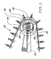
- FIG. 4 is a sectional view taken along the line 4 — 4 of FIG. 3 ;
- FIG. 5 is an enlarged side view of an outside idler wheel attachment of the track assembly of FIG. 2 ;
- FIG. 6 is a sectional view of a rigid member of the track assembly of FIG. 2 ;
- FIG. 7 is a top plan view of the attachment of the front track assembly of FIG. 1 to the all-terrain vehicle;
- FIG. 8 is a side elevational view of a rear track assembly of FIG. 1 , seen from the inside of the all-terrain vehicle;
- FIG. 9 is a top plan view of the attachment of the rear track assembly of FIG. 1 to the all-terrain vehicle;
- FIG. 10 is a sectional view similar to FIG. 4 but illustrating a second type of endless track.
- FIG. 11 is a sectional view similar to FIG. 4 but illustrating a third type of endless track.
- FIG. 1 shows an all-terrain vehicle 10 comprising a body 12 and four track assemblies (only two shown) according to the present invention arranged in a plane adjacent to each side of the vehicle 10 .
- the front track assembly 14 is better seen in FIG. 2 . It comprises a longitudinal endless track belt 23 and a mounting structure to mount the endless track belt 23 to the vehicle 10 .
- the mounting structure includes a track driving wheel 24 , a pair of inside idler wheels 26 , a pair of outside idler wheels 28 and supports to interconnect the wheels 24 , 26 and 28 as will be described hereinbelow.
- the endless track belt 23 is provided with inner lugs 30 on its inner surface 31 and with external lugs 32 on its outer surface 33 . It is wounded around the track driving wheel 24 and the idler wheels 28 and 26 .
- the track driving wheel 24 is mounted to a conventional hub 35 of the all-terrain vehicle 10 .
- the wheel 24 includes a first mounting plate 37 mounted to the hub 35 and a second mounting plate 34 mounted to the first plate 37 via four bolt and spacer assemblies 36 .
- a circular disk 38 is mounted to the bolt and spacer assemblies 36 and includes equidistant wide teeth 40 contacting the inner surface 31 of the track 23 .
- the equidistant teeth 40 are so located as to cooperate with some of the inner lugs 30 of the endless track belt 23 . More precisely, as can be better seen from FIG. 2 , the teeth 40 are spaced so that the distance between two consecutive teeth 40 spans the distance separating consecutive inner lugs 30 of the endless track belt 23 , in a meshing engagement, in such a way as to drive the endless track belt 23 .
- Each of the inside idler wheels 26 includes a peripheral portion in contact with the internal surface 31 of the track 23 .
- the wheels 26 are interconnected by a spacing element (not shown).
- each outer idler wheel 28 includes a peripheral portion in contact with the internal surface 31 of the track 23 .
- the wheels 28 are interconnected by a spacing element 42 .
- the wheels 24 , 26 and 28 are interconnected, as seen from the outside of the track assembly 14 , by an angled connecting element 44 .
- the angled connecting element 44 has a center portion 46 provided with an aperture 48 in which bearings 50 are mounted.
- a fastener 52 connects the connecting element 44 to the second plate 34 while allowing the angled connecting element 44 to pivot about the fastener.
- the connecting element 44 has a short arm 54 having a free end to which the inside idler wheels 26 are rotatably mounted.
- the connecting element 44 also has a long arm 56 having a free end to which the inside idler wheels 28 are rotatably mounted as will be further discussed hereinbelow.
- the connecting element 44 is better seen from the top plan view of FIG. 6 .
- FIG. 3 of the appended drawings as can be seen from the inside of the all-terrain vehicle 10 , the idler wheels 26 and 28 of the front track assembly 14 are also directly connected together by an elbowed connection element 58 .
- the inside idler wheels 26 are rotatably mounted to a first end of the elbowed connection element 58 while the outside idler wheels 28 are rotatably mounted to a second end of the elbowed connection element 58 .
- the tension of the endless track belt 23 is adjusted by the connection of the outside idler wheels 28 to the elements 44 and 58 .
- the connection of the wheels 28 to the elbowed connection element 58 will be described.
- a tension adjusting assembly according to another aspect of the present invention will be described.
- a distal end of the connection element 58 includes a slotted aperture 60 receiving a fastener 62 used to rotatably mount the wheels 28 to the assembly. By sliding the fastener 62 in the aperture 60 , it is possible to increase or decrease the tension on the track 23 .
- a cam element 64 having an outer periphery provided with notches 66 located at different distances from the attachment point of the element 64 , is mounted to the fastener 62 . By selecting which notch 66 is in contact with a fixed pin 68 of the element 58 , a predetermined tension may be maintained.
- the cam element 64 is provided with a handle 70 to facilitate the manipulation by a user.
- the overall profile of the track 23 is generally convex.
- the convex profile of the track 23 is created by a lug arrangement comprising two successive transverse rows of lugs arranged in a staggered relationship.
- a first transverse row of lugs contains three lugs 72 , 74 and 76 and a second row of lugs contains four lugs 78 , 80 , 82 and 84 . These lugs are symmetrical about a longitudinal axis (not shown).
- a first lateral lug 72 of the first row includes three ground-contacting surfaces separated by two indentations.
- the shape of lateral lug 72 is such that the ground contacting surfaces are generally transversally convex.
- a central lug 74 is centered about longitudinal axis and includes two ground-contacting surfaces separated by an indentation.
- the ground contacting surfaces are symmetrical about the longitudinal axis and are generally transversally convex.
- a second lateral lug 76 is a mirror image of lug 72 about the longitudinal axis.
- the first and second lateral lugs 72 and 76 are laterally spaced apart from the central lug 74 .
- a first intermediate lug 80 includes two ground-contacting surfaces separated by an indentation.
- the ground engaging surfaces are slightly transversally convex.
- a first external lug 78 includes two ground-contacting surfaces that are separated by an indentation and are transversally convex.
- the second intermediate lug 82 and the second external lug 84 are respectively mirror images of lugs 80 and 78 with respect to the longitudinal axis. For concision purposes, these lugs will not be further described herein.
- the endless track belt 23 further includes, for each row of lugs, a stiffening rod 71 , made of glass fibers for example.
- Each stiffening rod 71 is embedded in the material forming the track belt 23 so as to be generally parallel to the inner surface 31 thereof.
- the rods 71 provide enhanced rigidity to the endless track belt 23 .
- the enhanced rigidity of the track belt 23 has many advantages. For example, it helps the track to provide adequate traction even when the center portion of the track is not in direct contact with the ground, as illustrated in FIG. 4 . However, it has been found that this type of traction may be detrimental to the steering of the vehicle in some conditions.
- the ground contacting surfaces of symmetrical lugs 78 and 84 are not aligned with the outer surfaces of the other lugs to form a continuous profile. Indeed, the ground contacting surfaces of lugs 78 and 84 are more angled and exceed the convex profile defined by the other lugs. This configuration of the outer lugs is advantageous since it further prevents the vehicle from tipping over during sharp turns at high speed when the vehicle 10 is severely tilted.
- the way the front track assembly 14 is attached to the body 12 of the vehicle 10 differs from the way the rear track assembly 16 is attached to the body 12 of the vehicle 10 . These two attachments will be described hereinbelow.
- the front track assembly 14 is attached to the body 12 of the vehicle 10 in a fashion shown in FIGS. 4 and 7
- the rear track assembly 16 is attached to the body 12 of the vehicle 10 in a fashion shown in FIGS. 8 and 9 .
- the front track assembly 14 is mounted to a tubular wheel table 100 of the vehicle 10 by means of a generally triangular plate 102 fastened thereto by a plurality of U-bolts 104 , 106 , 108 and 110 .
- a rod 112 is connected between the elbowed connection element 58 and a pivot 114 of the tubular wheel table 100 .
- a first end of the rod 112 is attached to the elbowed connection element 58 by means of rubber damping elements 116 , in such a way as to allow a vertical movement at this point of the rod 112 in relation to the elbowed connection element 58 .
- a second end of the rod 112 is attached to the pivot 114 of the tubular wheel table 100 by means of an R-clip 120 , in such a way as to allow at this point a horizontal movement of the plate 102 holding the tubular wheel table 100 relative to the elbowed connection element 58 .
- the front track assembly 14 is further attached to the body 12 of the vehicle 10 through a conventional rod 150 of the suspension system of the vehicle 10 and a conventional rod 157 used for direction (see FIG. 4 ).
- the rear track assembly 16 is mounted to the body 12 of the vehicle 10 by a rod 212 .
- the rod 212 is connected on a first end to the elbowed connection element 58 ′ by means of a rubber damping attachment 216 . It is attached, on a second end, to a tubular chassis 130 of the body 12 of the vehicle 10 by means of a chipping joint 132 fastened thereto by an R-clip 134 .
- the present invention provides for track assemblies that are easily removed or mounted to the vehicle 10 , through using R-clips ( 120 and 134 ), which enable disconnecting the track assemblies from the vehicle in a simple manner.
- the interior surface 31 of the endless track belt 23 is provided with a plurality of equally spaced lugs 30 , which ensure a positive engagement with the teeth 40 provided on the outer circumference of the wheel 24 .
- the wheel 24 is coupled to a drive shaft, via the hub 30 , connected to an engine (not shown), in such a way that the engine drives the wheel 24 in rotation.
- the wheel 24 thus drives the endless track belt 23 by the meshing engagement of the teeth 40 with the internal lugs 30 of the endless track belt 23 .
- the external lugs 32 on the external circumference surface of the endless track belt 23 respectively exert a positive mechanical connection with the underlying ground surface that contributes to propel the vehicle 10 .
- FIG. 10 and FIG. 11 show sectional views similar to that of FIG. 4 but illustrating variants of an endless track that may be mounted to the track assembly of the present invention.
- the overall profile of the endless track belt 23 a is generally convex.
- the convex profile of the endless track belt 23 a is created by the same lug arrangement as that described hereinabove in relation to FIG. 4 .
- the endless track belt 23 a does not include stiffening rods under each row of lugs. Consequently, the rigidity of the endless track belt 23 a is less than the rigidity of the endless track belt 23 ( FIG. 4 ) and the profile of the endless track belt 23 a conforms itself to the profile of the ground. Since the pressure is more localized in the center of the endless track belt 23 a , a more punctually localized contact zone between the endless track belt 23 a and the ground 29 is created. In many cases, this punctually localized contact zone makes the vehicle 10 more maneuverable.
- FIG. 11 a third version of an endless track belt 23 b will be described.
- the endless track belt 23 b is wounded around the track driving wheel 24 and the idler wheels 28 and 26 , is still provided with inner lugs 30 on its inner surface 31 . However, its outer surface is provided with rectangular lugs 86 . Since there are no stiffening rods in the endless track belt 23 b , the endless track belt 23 b is free to conform itself to the ground 29 , as seen in FIG. 11 . Furthermore, since the pressure is exerted only in the middle of the endless track belt 23 b by the wide teeth 40 , a punctually localized contact zone between the endless track belt 23 b and the ground 29 is created.
- the endless track belts 23 a has a particularly punctually localized contact surface with the ground 29 . Indeed, since it is transversally convex, it generally contacts the ground 29 with a limited surface at any given time when the ground 29 is hard.
- the external lugs only exert a pressure on the ground 29 , when it is hard, in the vicinity of the wide teeth 40 if the wheel 24 .
- FIGS. 1 , 2 , 3 , and 8 it will be seen that the peripheral portion of the track driving wheel 24 in contact with the lower portion of the endless track belt 23 is below the peripheral portion of the idler wheels 26 , 28 . Therefore, on flat ground surfaces, only a punctually localized surface of endless track belt 23 , under the track driving wheel; 24 , is in contact with ground 29 .
- one skilled in the art could designed another convex profile of the external lugs of the endless track belts 23 and/or another arrangement of the mounting assembly of the endless track belts 23 to the vehicle 10 to obtain this “one point contact” feature without departing from the spirit and nature of the present invention.
- the all-terrain vehicle of the present invention provided with four endless track assemblies, can be used for a wide range of operations and terrain, while being highly mobile and offering good running performance.
- the endless track structure maintains an adequate configuration over a variety of surfaces.
- the present invention can be applied both in the case of a two-wheel drive vehicle wherein the power is typically applied only to the rear track belt assemblies and the front track assemblies merely facilitate steering, and in the case of a four-wheel vehicle, wherein power is independently provided to each one of the four track assemblies.
- the all-terrain vehicle 10 equipped with track assemblies according to the present invention, may be viewed as a snow vehicle since it may be used on snow as efficiently as conventional snow vehicles such as snowmobiles, for example.
- the one-point contact feature of the present invention allows the use of the all-terrain vehicle on harder surface without the usual drawbacks of tracked vehicles.
- the present track assembly system can equip all four wheels of an all-terrain vehicle or only the front or rear wheels thereof, since it only weakly reduces the speed of the vehicle relative to the underground surface.
- a further possibility would be to use track assemblies according to the present invention in place of the rear wheels of a vehicle, while mounting skis in place of the front wheels thereof.
Landscapes
- Engineering & Computer Science (AREA)
- Chemical & Material Sciences (AREA)
- Combustion & Propulsion (AREA)
- Transportation (AREA)
- Mechanical Engineering (AREA)
- Automatic Cycles, And Cycles In General (AREA)
- Tires In General (AREA)
Abstract
Description
Claims (12)
Priority Applications (2)
| Application Number | Priority Date | Filing Date | Title |
|---|---|---|---|
| US10/165,707 US6874586B2 (en) | 2002-02-27 | 2002-06-06 | Track assembly for an all-terrain vehicle |
| US10/967,245 US20050133281A1 (en) | 2002-02-27 | 2004-10-19 | Track assembly for an all-terrain vehicle |
Applications Claiming Priority (2)
| Application Number | Priority Date | Filing Date | Title |
|---|---|---|---|
| US10/087,103 US20030159859A1 (en) | 2002-02-27 | 2002-02-27 | Track assembly for an all-terrain vehicle |
| US10/165,707 US6874586B2 (en) | 2002-02-27 | 2002-06-06 | Track assembly for an all-terrain vehicle |
Related Parent Applications (1)
| Application Number | Title | Priority Date | Filing Date |
|---|---|---|---|
| US10/087,103 Continuation-In-Part US20030159859A1 (en) | 2002-02-27 | 2002-02-27 | Track assembly for an all-terrain vehicle |
Related Child Applications (1)
| Application Number | Title | Priority Date | Filing Date |
|---|---|---|---|
| US10/967,245 Continuation US20050133281A1 (en) | 2002-02-27 | 2004-10-19 | Track assembly for an all-terrain vehicle |
Publications (2)
| Publication Number | Publication Date |
|---|---|
| US20030159860A1 US20030159860A1 (en) | 2003-08-28 |
| US6874586B2 true US6874586B2 (en) | 2005-04-05 |
Family
ID=34681090
Family Applications (2)
| Application Number | Title | Priority Date | Filing Date |
|---|---|---|---|
| US10/165,707 Expired - Lifetime US6874586B2 (en) | 2002-02-27 | 2002-06-06 | Track assembly for an all-terrain vehicle |
| US10/967,245 Abandoned US20050133281A1 (en) | 2002-02-27 | 2004-10-19 | Track assembly for an all-terrain vehicle |
Family Applications After (1)
| Application Number | Title | Priority Date | Filing Date |
|---|---|---|---|
| US10/967,245 Abandoned US20050133281A1 (en) | 2002-02-27 | 2004-10-19 | Track assembly for an all-terrain vehicle |
Country Status (1)
| Country | Link |
|---|---|
| US (2) | US6874586B2 (en) |
Cited By (37)
| Publication number | Priority date | Publication date | Assignee | Title |
|---|---|---|---|---|
| US20040168837A1 (en) * | 2002-11-27 | 2004-09-02 | Universite De Sherbrooke | Modular robotic platform |
| US20060181148A1 (en) * | 2005-01-28 | 2006-08-17 | Robert Bessette | Traction assembly for a vehicle |
| US20060232026A1 (en) * | 2005-02-14 | 2006-10-19 | Kyle Reeves | Rear Drive Assembly for a Snow Bicycle |
| US20070169968A1 (en) * | 2006-01-24 | 2007-07-26 | Andre Todd | Traction assembly for a vehicle |
| US20070240917A1 (en) * | 2004-12-21 | 2007-10-18 | Bombardier Recreational Products Inc. | Endless Belt Drive for a Vehicle |
| WO2006050527A3 (en) * | 2004-11-03 | 2007-12-06 | Imura Internat U S A | Pressure cooker |
| WO2008041879A1 (en) * | 2006-08-21 | 2008-04-10 | Eduard Arkadjevich Geraschenko | Tracked cross-country motor vehicle |
| US20080257616A1 (en) * | 2005-09-08 | 2008-10-23 | Ake Olsson | Tracked Vehicle, Especially a Snow Scooter |
| US7513327B1 (en) * | 2005-10-13 | 2009-04-07 | Kent Peterson | System for converting a recreational vehicle |
| US20090090570A1 (en) * | 2007-10-03 | 2009-04-09 | Zuchoski Jeremie | Track assembly for an all-terrain vehicle |
| US20090255745A1 (en) * | 2007-01-24 | 2009-10-15 | Polaris Industries Inc. | Motorized snowboard |
| US20090266628A1 (en) * | 2008-04-24 | 2009-10-29 | Hagen Schempf | Stair climbing tread hardware for a robot |
| US20120211288A1 (en) * | 2011-02-18 | 2012-08-23 | Angelo Afanador | Triangle Track Vehicle Wheel |
| USD682160S1 (en) * | 2011-11-02 | 2013-05-14 | Camoplast Solideal Inc. | Lower frame of a track system for an all-terrain vehicle |
| USD682159S1 (en) * | 2011-11-02 | 2013-05-14 | Camoplast Solideal Inc. | Upper frame of a track system for an all-terrain vehicle |
| USD682161S1 (en) * | 2011-11-02 | 2013-05-14 | Camoplast Solideal Inc. | Frame of a track system for an all-terrain vehicle |
| US8574021B2 (en) | 2011-09-23 | 2013-11-05 | Mattel, Inc. | Foldable toy vehicles |
| US20150136497A1 (en) * | 2013-10-16 | 2015-05-21 | Vincent Morin | Track System |
| US9067631B1 (en) | 2010-12-14 | 2015-06-30 | Camoplast Solideal Inc. | Endless track for traction of a vehicle |
| US9211921B2 (en) | 2010-11-02 | 2015-12-15 | Camso Inc. | Track assembly for providing traction to an off-road vehicle such as an all-terrain vehicle (ATV) or a snowmobile |
| US9334001B2 (en) | 2010-12-14 | 2016-05-10 | Camso Inc. | Drive sprocket, drive lug configuration and track drive arrangement for an endless track vehicle |
| US9511805B2 (en) | 2009-12-11 | 2016-12-06 | Camso Inc. | Endless track for propelling a vehicle, with edge-cutting resistance |
| US9676430B2 (en) | 2014-09-16 | 2017-06-13 | David Owen Mattson | Vehicle track assembly |
| US10252757B2 (en) | 2016-04-12 | 2019-04-09 | Soucy International Inc. | Track system for attachment to a vehicle |
| US10421507B2 (en) * | 2015-02-13 | 2019-09-24 | Moorend Ltd. | Apparatus arranged for converting a wheeled vehicle to a tracked vehicle |
| US10538282B2 (en) * | 2015-02-13 | 2020-01-21 | Moorend Ltd. | Apparatus arranged for converting a wheeled vehicle to a tracked vehicle |
| US10783723B2 (en) | 2015-06-29 | 2020-09-22 | Camso Inc. | Systems and methods for monitoring a track system for traction of a vehicle |
| US10889322B2 (en) | 2018-07-30 | 2021-01-12 | Terra Drive Systems, Inc. | Oscillation limited driven steering track assembly |
| US10933877B2 (en) | 2010-12-14 | 2021-03-02 | Camso Inc. | Track drive mode management system and methods |
| US10940902B2 (en) | 2017-02-15 | 2021-03-09 | Soucy International Inc. | Track assembly and vehicle |
| US11046377B2 (en) | 2015-03-04 | 2021-06-29 | Camso Inc. | Track system for traction of a vehicle |
| US11148745B1 (en) * | 2019-02-26 | 2021-10-19 | Gregory Parker | Hydraulic drive powered endless track drive motorcycle |
| US11186330B2 (en) | 2010-06-30 | 2021-11-30 | Camso Inc. | Track assembly for an off-road vehicle |
| US11780513B2 (en) * | 2018-02-15 | 2023-10-10 | Soucy International Inc. | Rear track assembly for a vehicle |
| US11835955B2 (en) | 2017-12-08 | 2023-12-05 | Camso Inc. | Systems and methods for monitoring off-road vehicles |
| US12090795B2 (en) | 2018-08-30 | 2024-09-17 | Camso Inc. | Systems and methods for monitoring vehicles with tires |
| US12254616B2 (en) | 2018-08-30 | 2025-03-18 | Camso Inc. | Systems and methods for monitoring tracked vehicles |
Families Citing this family (9)
| Publication number | Priority date | Publication date | Assignee | Title |
|---|---|---|---|---|
| US20060060395A1 (en) * | 2004-06-09 | 2006-03-23 | Denis Boivin | Track assembly for an all-terrain vehicle |
| GB2435868A (en) * | 2006-03-06 | 2007-09-12 | Stephen John Heard | Vehicle mountable crawler assembly with frictionally driven track |
| US20110074210A1 (en) * | 2006-09-22 | 2011-03-31 | Michel Paradis | Noiseless Elastomeric Tracks For Tracked Vehicles |
| US10266216B2 (en) | 2010-04-20 | 2019-04-23 | Denis Boivin | Track system having anti-diving flaps |
| US8776931B2 (en) | 2010-04-20 | 2014-07-15 | Denis Boivin | Track system for an all-wheel drive vehicle |
| US8613332B2 (en) * | 2012-01-07 | 2013-12-24 | Oak Novations, Ltd. | Removable track drive |
| CN105626830B (en) * | 2015-10-18 | 2020-03-31 | 刘金松 | Combined chain wheel |
| CN111846069A (en) * | 2016-03-26 | 2020-10-30 | 刘金松 | AI balance car |
| US11963916B2 (en) * | 2019-12-30 | 2024-04-23 | Stryker Corporation | Track assembly for patient transport apparatus |
Citations (33)
| Publication number | Priority date | Publication date | Assignee | Title |
|---|---|---|---|---|
| US916601A (en) * | 1908-03-14 | 1909-03-30 | David Roberts | Traction-engine. |
| US1031174A (en) * | 1912-01-30 | 1912-07-02 | Severo Campo Fregoso | Wheel. |
| US1038569A (en) * | 1912-01-02 | 1912-09-17 | Fred V Grover | Attachment for automobile-wheels. |
| US1062318A (en) * | 1911-03-16 | 1913-05-20 | George C Berlin | Driving-gear. |
| US1117640A (en) * | 1911-08-07 | 1914-11-17 | Charles B Coon | Combined traction-wheel and track. |
| US1228687A (en) * | 1913-11-17 | 1917-06-05 | G W Parsons Company | Caterpillar-wheel. |
| US1453782A (en) * | 1921-06-18 | 1923-05-01 | Bell John Thomas | Tractor appliance for trucks |
| US1774835A (en) * | 1929-04-04 | 1930-09-02 | Alvin O Lombard | Traction device |
| US2461850A (en) * | 1946-05-31 | 1949-02-15 | Goodrich Co B F | Tractor vehicle |
| US2467947A (en) * | 1945-05-22 | 1949-04-19 | Goodrich Co B F | Traction apparatus |
| US2496136A (en) * | 1948-01-02 | 1950-01-31 | Goodrich Co B F | Undercarriage for self-laying track type vehicles |
| US3590935A (en) * | 1968-11-04 | 1971-07-06 | Angelo Celia | Clutch and attachment device for vehicle wheels |
| US3598454A (en) * | 1969-05-26 | 1971-08-10 | Textron Inc | Vehicle drive track stiffener |
| US3688858A (en) * | 1969-09-12 | 1972-09-05 | Outboard Marine Corp | All-terrain vehicle |
| US3841424A (en) * | 1971-12-27 | 1974-10-15 | Caterpillar Tractor Co | Triangular track resilient bogie suspension |
| US3894778A (en) * | 1974-01-25 | 1975-07-15 | Us Army | Cable-actuated track tensioner |
| US3938606A (en) * | 1974-11-04 | 1976-02-17 | Caterpillar Tractor Co. | Track-idler recoil suspension mechanism |
| US4194584A (en) | 1978-07-17 | 1980-03-25 | Delany James F | Variable terrain vehicle |
| US4232753A (en) | 1977-10-28 | 1980-11-11 | Konetehdas Maskinfabrik Norcar Ky Kb | Endless track vehicle |
| US4483407A (en) | 1982-03-26 | 1984-11-20 | Hitachi, Ltd. | Variable configuration track laying vehicle |
| US4714302A (en) * | 1978-01-02 | 1987-12-22 | Skega Aktiebolag | Vehicle track |
| US5340205A (en) * | 1992-11-13 | 1994-08-23 | Deere & Company | Suspension system for a tracked vehicle |
| US5474146A (en) | 1988-12-06 | 1995-12-12 | Honda Giken Kogyo Kabushiki Kaisha | Snow vehicle |
| US5515936A (en) | 1995-07-10 | 1996-05-14 | Vehicules Ts Bellechasse Ltee | Track tensioning system for endless track propelled vehicle |
| US5607210A (en) | 1994-12-21 | 1997-03-04 | Brazier; Glen | Wheel mount track conversion assembly |
| US5655615A (en) | 1994-01-06 | 1997-08-12 | Mick; Jeffrey | Wheeled vehicle for distributing agricultural materials in fields having uneven terrain |
| US5954148A (en) | 1995-10-18 | 1999-09-21 | Kabushiki Kaisha Toyoda Jidoshokki Seisakusho | Crawler apparatus for vehicle |
| US6006847A (en) | 1997-02-18 | 1999-12-28 | Knight; Doyle D | Endless track structure for light wheeled vehicle |
| US6095275A (en) | 1995-12-19 | 2000-08-01 | Shaw; Charles T. | Conversion system for all terrain vehicles |
| US6129426A (en) * | 1998-02-25 | 2000-10-10 | Tucker Sno-Cat Corporation | Tracked vehicle with improved guide wheel assembly |
| US6132287A (en) | 1997-08-19 | 2000-10-17 | Kuralt; Richard Blake | Transforming tracked toy vehicle |
| US6199646B1 (en) | 1996-08-01 | 2001-03-13 | Kubota Corporation | Working vehicle with semicrawlers |
| US6626258B1 (en) * | 1998-02-25 | 2003-09-30 | Vernal D. Forbes | Snow vehicle |
-
2002
- 2002-06-06 US US10/165,707 patent/US6874586B2/en not_active Expired - Lifetime
-
2004
- 2004-10-19 US US10/967,245 patent/US20050133281A1/en not_active Abandoned
Patent Citations (33)
| Publication number | Priority date | Publication date | Assignee | Title |
|---|---|---|---|---|
| US916601A (en) * | 1908-03-14 | 1909-03-30 | David Roberts | Traction-engine. |
| US1062318A (en) * | 1911-03-16 | 1913-05-20 | George C Berlin | Driving-gear. |
| US1117640A (en) * | 1911-08-07 | 1914-11-17 | Charles B Coon | Combined traction-wheel and track. |
| US1038569A (en) * | 1912-01-02 | 1912-09-17 | Fred V Grover | Attachment for automobile-wheels. |
| US1031174A (en) * | 1912-01-30 | 1912-07-02 | Severo Campo Fregoso | Wheel. |
| US1228687A (en) * | 1913-11-17 | 1917-06-05 | G W Parsons Company | Caterpillar-wheel. |
| US1453782A (en) * | 1921-06-18 | 1923-05-01 | Bell John Thomas | Tractor appliance for trucks |
| US1774835A (en) * | 1929-04-04 | 1930-09-02 | Alvin O Lombard | Traction device |
| US2467947A (en) * | 1945-05-22 | 1949-04-19 | Goodrich Co B F | Traction apparatus |
| US2461850A (en) * | 1946-05-31 | 1949-02-15 | Goodrich Co B F | Tractor vehicle |
| US2496136A (en) * | 1948-01-02 | 1950-01-31 | Goodrich Co B F | Undercarriage for self-laying track type vehicles |
| US3590935A (en) * | 1968-11-04 | 1971-07-06 | Angelo Celia | Clutch and attachment device for vehicle wheels |
| US3598454A (en) * | 1969-05-26 | 1971-08-10 | Textron Inc | Vehicle drive track stiffener |
| US3688858A (en) * | 1969-09-12 | 1972-09-05 | Outboard Marine Corp | All-terrain vehicle |
| US3841424A (en) * | 1971-12-27 | 1974-10-15 | Caterpillar Tractor Co | Triangular track resilient bogie suspension |
| US3894778A (en) * | 1974-01-25 | 1975-07-15 | Us Army | Cable-actuated track tensioner |
| US3938606A (en) * | 1974-11-04 | 1976-02-17 | Caterpillar Tractor Co. | Track-idler recoil suspension mechanism |
| US4232753A (en) | 1977-10-28 | 1980-11-11 | Konetehdas Maskinfabrik Norcar Ky Kb | Endless track vehicle |
| US4714302A (en) * | 1978-01-02 | 1987-12-22 | Skega Aktiebolag | Vehicle track |
| US4194584A (en) | 1978-07-17 | 1980-03-25 | Delany James F | Variable terrain vehicle |
| US4483407A (en) | 1982-03-26 | 1984-11-20 | Hitachi, Ltd. | Variable configuration track laying vehicle |
| US5474146A (en) | 1988-12-06 | 1995-12-12 | Honda Giken Kogyo Kabushiki Kaisha | Snow vehicle |
| US5340205A (en) * | 1992-11-13 | 1994-08-23 | Deere & Company | Suspension system for a tracked vehicle |
| US5655615A (en) | 1994-01-06 | 1997-08-12 | Mick; Jeffrey | Wheeled vehicle for distributing agricultural materials in fields having uneven terrain |
| US5607210A (en) | 1994-12-21 | 1997-03-04 | Brazier; Glen | Wheel mount track conversion assembly |
| US5515936A (en) | 1995-07-10 | 1996-05-14 | Vehicules Ts Bellechasse Ltee | Track tensioning system for endless track propelled vehicle |
| US5954148A (en) | 1995-10-18 | 1999-09-21 | Kabushiki Kaisha Toyoda Jidoshokki Seisakusho | Crawler apparatus for vehicle |
| US6095275A (en) | 1995-12-19 | 2000-08-01 | Shaw; Charles T. | Conversion system for all terrain vehicles |
| US6199646B1 (en) | 1996-08-01 | 2001-03-13 | Kubota Corporation | Working vehicle with semicrawlers |
| US6006847A (en) | 1997-02-18 | 1999-12-28 | Knight; Doyle D | Endless track structure for light wheeled vehicle |
| US6132287A (en) | 1997-08-19 | 2000-10-17 | Kuralt; Richard Blake | Transforming tracked toy vehicle |
| US6129426A (en) * | 1998-02-25 | 2000-10-10 | Tucker Sno-Cat Corporation | Tracked vehicle with improved guide wheel assembly |
| US6626258B1 (en) * | 1998-02-25 | 2003-09-30 | Vernal D. Forbes | Snow vehicle |
Cited By (64)
| Publication number | Priority date | Publication date | Assignee | Title |
|---|---|---|---|---|
| US20040168837A1 (en) * | 2002-11-27 | 2004-09-02 | Universite De Sherbrooke | Modular robotic platform |
| WO2006050527A3 (en) * | 2004-11-03 | 2007-12-06 | Imura Internat U S A | Pressure cooker |
| US8056655B2 (en) | 2004-12-21 | 2011-11-15 | Bombardier Recreational Products Inc. | Endless belt drive for a vehicle |
| US7712557B2 (en) * | 2004-12-21 | 2010-05-11 | Bombardier Recreational Products Inc. | Endless belt drive for a vehicle |
| US20100230185A1 (en) * | 2004-12-21 | 2010-09-16 | Bombardier Recreational Products Inc. | Endless belt drive for a vehicle |
| US20070240917A1 (en) * | 2004-12-21 | 2007-10-18 | Bombardier Recreational Products Inc. | Endless Belt Drive for a Vehicle |
| US20080156548A1 (en) * | 2004-12-21 | 2008-07-03 | Bombardier Recreational Products Inc. | Endless Belt Drive for a Vehicle |
| US20060181148A1 (en) * | 2005-01-28 | 2006-08-17 | Robert Bessette | Traction assembly for a vehicle |
| US7497530B2 (en) | 2005-01-28 | 2009-03-03 | Soucy International Inc. | Traction assembly for a vehicle |
| US20060232026A1 (en) * | 2005-02-14 | 2006-10-19 | Kyle Reeves | Rear Drive Assembly for a Snow Bicycle |
| US7232130B2 (en) * | 2005-02-14 | 2007-06-19 | Kyle Reeves | Rear drive assembly for a snow bicycle |
| US20080257616A1 (en) * | 2005-09-08 | 2008-10-23 | Ake Olsson | Tracked Vehicle, Especially a Snow Scooter |
| US7845448B2 (en) * | 2005-09-08 | 2010-12-07 | Ake Olsson | Tracked vehicle, especially a snow scooter |
| US7513327B1 (en) * | 2005-10-13 | 2009-04-07 | Kent Peterson | System for converting a recreational vehicle |
| US8056656B2 (en) | 2006-01-24 | 2011-11-15 | Soucy International Inc. | Anti-torque system for a traction assembly |
| US20110079980A1 (en) * | 2006-01-24 | 2011-04-07 | Todd Andre | Anti-torque system for a traction assembly |
| US7870914B2 (en) | 2006-01-24 | 2011-01-18 | Soucy International Inc. | Traction assembly for a vehicle |
| US20070169968A1 (en) * | 2006-01-24 | 2007-07-26 | Andre Todd | Traction assembly for a vehicle |
| WO2008041879A1 (en) * | 2006-08-21 | 2008-04-10 | Eduard Arkadjevich Geraschenko | Tracked cross-country motor vehicle |
| US20090255745A1 (en) * | 2007-01-24 | 2009-10-15 | Polaris Industries Inc. | Motorized snowboard |
| US20100108421A1 (en) * | 2007-10-03 | 2010-05-06 | Camoplast Inc. | Track assembly for an all-terrain vehicle |
| US20090090570A1 (en) * | 2007-10-03 | 2009-04-09 | Zuchoski Jeremie | Track assembly for an all-terrain vehicle |
| US8347991B2 (en) * | 2007-10-03 | 2013-01-08 | Camoplast Solideal, Inc. | Track assembly for an all-terrain vehicle |
| US10005507B2 (en) | 2007-10-03 | 2018-06-26 | Camso Inc. | Track assembly for an all-terrain vehicle |
| US8662214B2 (en) * | 2007-10-03 | 2014-03-04 | Camoplast Solideal Inc. | Track assembly for an all-terrain vehicle |
| US20090266628A1 (en) * | 2008-04-24 | 2009-10-29 | Hagen Schempf | Stair climbing tread hardware for a robot |
| US9511805B2 (en) | 2009-12-11 | 2016-12-06 | Camso Inc. | Endless track for propelling a vehicle, with edge-cutting resistance |
| US11186330B2 (en) | 2010-06-30 | 2021-11-30 | Camso Inc. | Track assembly for an off-road vehicle |
| US9914497B2 (en) | 2010-11-02 | 2018-03-13 | Camso Inc. | Track assembly for providing traction to an off-road vehicle such as an all-terrain vehicle (ATV) or a snowmobile |
| US9211921B2 (en) | 2010-11-02 | 2015-12-15 | Camso Inc. | Track assembly for providing traction to an off-road vehicle such as an all-terrain vehicle (ATV) or a snowmobile |
| US9162718B2 (en) | 2010-12-14 | 2015-10-20 | Camso Inc. | Endless track for traction of a vehicle |
| US12583458B2 (en) | 2010-12-14 | 2026-03-24 | Camso Inc. | Track drive mode management system and methods |
| US9067631B1 (en) | 2010-12-14 | 2015-06-30 | Camoplast Solideal Inc. | Endless track for traction of a vehicle |
| US9334001B2 (en) | 2010-12-14 | 2016-05-10 | Camso Inc. | Drive sprocket, drive lug configuration and track drive arrangement for an endless track vehicle |
| US10933877B2 (en) | 2010-12-14 | 2021-03-02 | Camso Inc. | Track drive mode management system and methods |
| US10328982B2 (en) | 2010-12-14 | 2019-06-25 | Camso Inc. | Drive sprocket, drive lug configuration and track drive arrangement for an endless track vehicle |
| US8695735B2 (en) * | 2011-02-18 | 2014-04-15 | Angelo Afanador | Triangle track vehicle wheel |
| US20120211288A1 (en) * | 2011-02-18 | 2012-08-23 | Angelo Afanador | Triangle Track Vehicle Wheel |
| US8574021B2 (en) | 2011-09-23 | 2013-11-05 | Mattel, Inc. | Foldable toy vehicles |
| USD682160S1 (en) * | 2011-11-02 | 2013-05-14 | Camoplast Solideal Inc. | Lower frame of a track system for an all-terrain vehicle |
| USD682159S1 (en) * | 2011-11-02 | 2013-05-14 | Camoplast Solideal Inc. | Upper frame of a track system for an all-terrain vehicle |
| USD682161S1 (en) * | 2011-11-02 | 2013-05-14 | Camoplast Solideal Inc. | Frame of a track system for an all-terrain vehicle |
| US9981703B2 (en) * | 2013-10-16 | 2018-05-29 | Soucy International Inc. | Track system |
| US20150136497A1 (en) * | 2013-10-16 | 2015-05-21 | Vincent Morin | Track System |
| US10137948B2 (en) | 2014-09-16 | 2018-11-27 | David Owen Mattson | Vehicle track assembly having track rotation indicator pole |
| US9676430B2 (en) | 2014-09-16 | 2017-06-13 | David Owen Mattson | Vehicle track assembly |
| US10538282B2 (en) * | 2015-02-13 | 2020-01-21 | Moorend Ltd. | Apparatus arranged for converting a wheeled vehicle to a tracked vehicle |
| US10421507B2 (en) * | 2015-02-13 | 2019-09-24 | Moorend Ltd. | Apparatus arranged for converting a wheeled vehicle to a tracked vehicle |
| US11046377B2 (en) | 2015-03-04 | 2021-06-29 | Camso Inc. | Track system for traction of a vehicle |
| US11167810B2 (en) | 2015-03-04 | 2021-11-09 | Camso Inc. | Track system for traction of a vehicle |
| US11897558B2 (en) | 2015-03-04 | 2024-02-13 | Camso Inc. | Track system for traction of a vehicle |
| US10783723B2 (en) | 2015-06-29 | 2020-09-22 | Camso Inc. | Systems and methods for monitoring a track system for traction of a vehicle |
| US12008846B2 (en) | 2015-06-29 | 2024-06-11 | Camso Inc. | Systems and methods for monitoring a track system for traction of a vehicle |
| US10252757B2 (en) | 2016-04-12 | 2019-04-09 | Soucy International Inc. | Track system for attachment to a vehicle |
| US12012163B2 (en) | 2017-02-15 | 2024-06-18 | Soucy International Inc. | Track assembly and vehicle |
| US10940902B2 (en) | 2017-02-15 | 2021-03-09 | Soucy International Inc. | Track assembly and vehicle |
| US11097793B2 (en) | 2017-02-15 | 2021-08-24 | Soucy International Inc. | Rear track assembly for a vehicle |
| US12351257B2 (en) | 2017-02-15 | 2025-07-08 | Soucy International Inc. | Track assembly and vehicle |
| US11835955B2 (en) | 2017-12-08 | 2023-12-05 | Camso Inc. | Systems and methods for monitoring off-road vehicles |
| US11780513B2 (en) * | 2018-02-15 | 2023-10-10 | Soucy International Inc. | Rear track assembly for a vehicle |
| US10889322B2 (en) | 2018-07-30 | 2021-01-12 | Terra Drive Systems, Inc. | Oscillation limited driven steering track assembly |
| US12090795B2 (en) | 2018-08-30 | 2024-09-17 | Camso Inc. | Systems and methods for monitoring vehicles with tires |
| US12254616B2 (en) | 2018-08-30 | 2025-03-18 | Camso Inc. | Systems and methods for monitoring tracked vehicles |
| US11148745B1 (en) * | 2019-02-26 | 2021-10-19 | Gregory Parker | Hydraulic drive powered endless track drive motorcycle |
Also Published As
| Publication number | Publication date |
|---|---|
| US20050133281A1 (en) | 2005-06-23 |
| US20030159860A1 (en) | 2003-08-28 |
Similar Documents
| Publication | Publication Date | Title |
|---|---|---|
| US6874586B2 (en) | Track assembly for an all-terrain vehicle | |
| US7497530B2 (en) | Traction assembly for a vehicle | |
| CA2319934C (en) | Rubber-band track with various hardnesses | |
| US9033430B2 (en) | Track assembly for an all-terrain vehicle (ATV) or other tracked vehicle | |
| CA2881212C (en) | A track assembly for an all-terrain vehicle | |
| US4719983A (en) | Device and attendant equipment for converting a motor-scooter into a vehicle suitable for operating on snowy ground | |
| US9346500B2 (en) | Track and drive sprockets for a tracked vehicle | |
| US20030159859A1 (en) | Track assembly for an all-terrain vehicle | |
| US8007058B2 (en) | Traction assembly with endless track having variable ground-contacting area | |
| CA2414655C (en) | Traction band and sprocket for vehicles | |
| CA2825509C (en) | Track assembly for an all-terrain vehicle | |
| CA2854554C (en) | Track assembly for an all-terrain vehicle | |
| US4950211A (en) | Track drive sprocket wheel for snow grooming vehicle | |
| US20020033643A1 (en) | Endless track for a vehicle | |
| US20070063584A1 (en) | Snowmobile traction band | |
| US20060090939A1 (en) | Removable snowmobile repositioning device | |
| CA1270022A (en) | Rear crawler track retrofit for garden and lawn tractors | |
| US20210114690A1 (en) | Drive track for a tracked vehicle | |
| US20250340258A1 (en) | Drive wheel for track systems and track system having same | |
| JPH09123953A (en) | Suspension structure of tracked vehicle | |
| JP4144803B2 (en) | Snowmobile cart | |
| CA2495642A1 (en) | Traction assembly for a vehicle |
Legal Events
| Date | Code | Title | Description |
|---|---|---|---|
| AS | Assignment |
Owner name: A & D BOIVIN DESIGN INC., CANADA Free format text: ASSIGNMENT OF ASSIGNORS INTEREST;ASSIGNORS:BOIVIN, DENIS;BIOVIN, ALAIN;REEL/FRAME:015651/0567 Effective date: 20020227 |
|
| STCF | Information on status: patent grant |
Free format text: PATENTED CASE |
|
| AS | Assignment |
Owner name: CAMOPLAST INC., CANADA Free format text: ASSIGNMENT OF ASSIGNORS INTEREST;ASSIGNOR:A & D BOIVIN DESIGN INC.;REEL/FRAME:017619/0559 Effective date: 20060502 |
|
| FEPP | Fee payment procedure |
Free format text: PAT HOLDER NO LONGER CLAIMS SMALL ENTITY STATUS, ENTITY STATUS SET TO UNDISCOUNTED (ORIGINAL EVENT CODE: STOL); ENTITY STATUS OF PATENT OWNER: LARGE ENTITY |
|
| REFU | Refund |
Free format text: REFUND - SURCHARGE, PETITION TO ACCEPT PYMT AFTER EXP, UNINTENTIONAL (ORIGINAL EVENT CODE: R2551); ENTITY STATUS OF PATENT OWNER: LARGE ENTITY |
|
| FEPP | Fee payment procedure |
Free format text: PAYOR NUMBER ASSIGNED (ORIGINAL EVENT CODE: ASPN); ENTITY STATUS OF PATENT OWNER: LARGE ENTITY |
|
| FPAY | Fee payment |
Year of fee payment: 4 |
|
| AS | Assignment |
Owner name: CAMOPLAST INC., CANADA Free format text: CORRECTIVE ASSIGNMENT TO CORRECT THE APPLICATION NUMBER 11/165,707 THAT IS TO BE REMOVED FROM THE ASSIGNMENT PREVIOUSLY RECORDED ON REEL 017619 FRAME 0559. ASSIGNOR(S) HEREBY CONFIRMS THE APPLICATION NUMBER 11/165,707 WAS NOT TO BE ASSIGNED;ASSIGNOR:A & D BOIVIN DESIGN INC.;REEL/FRAME:025592/0182 Effective date: 20060502 |
|
| FPAY | Fee payment |
Year of fee payment: 8 |
|
| AS | Assignment |
Owner name: CANADIAN IMPERIAL BANK OF COMMERCE, AS AGENT, CANA Free format text: SECURITY AGREEMENT;ASSIGNOR:CAMOPLAST SOLIDEAL INC.;REEL/FRAME:031006/0511 Effective date: 20130808 |
|
| FPAY | Fee payment |
Year of fee payment: 12 |
|
| AS | Assignment |
Owner name: CAMSO INC. (FORMERLY CAMOPLAST SOLIDEAL INC.), CAN Free format text: RELEASE BY SECURED PARTY;ASSIGNOR:CANADIAN IMPERIAL BANK OF COMMERCE;REEL/FRAME:050022/0767 Effective date: 20190604 |