US6867945B2 - Cassette loading device - Google Patents
Cassette loading device Download PDFInfo
- Publication number
- US6867945B2 US6867945B2 US10/159,740 US15974002A US6867945B2 US 6867945 B2 US6867945 B2 US 6867945B2 US 15974002 A US15974002 A US 15974002A US 6867945 B2 US6867945 B2 US 6867945B2
- Authority
- US
- United States
- Prior art keywords
- engagement member
- subarm
- holder
- main arm
- cassette
- Prior art date
- Legal status (The legal status is an assumption and is not a legal conclusion. Google has not performed a legal analysis and makes no representation as to the accuracy of the status listed.)
- Expired - Fee Related, expires
Links
Images


Classifications
-
- G—PHYSICS
- G11—INFORMATION STORAGE
- G11B—INFORMATION STORAGE BASED ON RELATIVE MOVEMENT BETWEEN RECORD CARRIER AND TRANSDUCER
- G11B15/00—Driving, starting or stopping record carriers of filamentary or web form; Driving both such record carriers and heads; Guiding such record carriers or containers therefor; Control thereof; Control of operating function
- G11B15/675—Guiding containers, e.g. loading, ejecting cassettes
- G11B15/67563—Guiding containers, e.g. loading, ejecting cassettes with movement of the cassette perpendicular to its main side, i.e. top loading
- G11B15/67565—Guiding containers, e.g. loading, ejecting cassettes with movement of the cassette perpendicular to its main side, i.e. top loading of the cassette with holder
Definitions
- the present invention relates to a cassette loading device used for a magnetic recording/reproducing apparatus.
- Videotape camera-recorders include a cassette loading device for loading a cassette into the recorder.
- FIGS. 8A-8C illustrate specific portions of the conventional cassette loading device.
- the aforementioned Patent Publication uses member names such as a “boss 20 ”, a “support pin (flange) 21 ”, and a “pin hole 17 b ”, these members are respectively referred to herein as a “support pin boss 20 ”, a “support pin 21 ”, and a “pin insertion hole 17 b ” and, as shown in FIG. 8C , reference numeral 22 is also used to denote a “support pin flange”.
- FIG. 8A is a perspective view showing a portion of the conventional cassette loading device.
- FIG. 8B is a side view for explaining an insertion direction of the support pin 21 .
- FIG. 8C is a cross-sectional view of the support pin 21 .
- the conventional cassette loading device includes a cassette holder 11 which receives a cassette (not shown).
- the cassette holder 11 has a flat box-like structure and receives a cassette from the right side of FIG. 8 A.
- the cassette holder 11 can be moved up and down whilst being kept horizontal by a holder retention mechanism including two pairs of arms 13 and 15 .
- a holder retention mechanism including two pairs of arms 13 and 15 .
- the arms 13 and 15 are pivotably supported by a support pin 16 .
- One end of the arms 13 and 15 is pivotably attached to a chassis sidewall 17 and a holder sidewall 11 a , respectively.
- the other end of the arms 13 and 15 is supported by support pins 12 and 21 so as to be in communication with the holder sidewall 11 a and the chassis sidewall 17 , respectively.
- the support pins 12 and 21 are respectively engaged with a slot 11 b provided in the holder sidewall 11 a and a slot 17 a provided in the chassis sidewall 17 in a slidable manner.
- the slot 17 a extends along a longitudinal direction of the chassis sidewall 17 .
- the pin insertion hole 17 b is provided at the center of the upper side of the slot 17 a , such that the slot 17 a and the pin insertion hole 17 b are connected.
- the pin insertion hole 17 b is large enough to allow the support pin flange 22 to pass therethrough.
- a width of the slot 17 a excluding the pin insertion hole 17 b is narrower than a diameter of the support pin flange 22 .
- the support pin boss 20 of the arm 15 is narrower than the width of the slot 17 a and is engaged with the slot 17 a so as to be slidable along the longitudinal direction of the slot 17 a.
- the pin insertion hole 17 b is covered by a frame 19 a of a cassette slip prevention element 19 . This prevents the support pin 21 from being disengaged from the slot 17 a during operation when the cassette holder 11 is moved up and down.
- the cassette holder 11 When the support pin flange 22 is positioned at the end of the slot 17 a shown in FIG. 8B by a dashed circle, the cassette holder 11 is in an uppermost position of its moving range. When the pin flange 22 is positioned at the other end of the slot 17 a , the cassette holder 11 is in a lowermost position of its moving range.
- a cover member is required to cover the pin insertion hole 17 b so as to prevent the support pin 21 from being disengaged from the slot 17 a during operation, e.g., the frame 19 a of the cassette slip prevention element 19 .
- the number of parts used for the conventional cassette loading device is increased.
- a cassette loading device including: a holder for retaining a cassette therein, the holder reciprocating between a first holder position for insertion of the cassette into the holder and a second holder position for loading the cassette into a body; a main arm including: a first main arm engagement member provided at one end of the main arm for engagement with a first holder engagement member provided at a near side of a side face of the holder such that the main arm is rotatable about the first holder engagement member; and a second main arm engagement member provided at another end of the main arm for engagement with a second body engagement member provided at a far side of the body such that the main arm is slidable along the second body engagement member; and a subarm including: a first subarm engagement member provided at one end of the subarm for engagement with a first body engagement member provided at a near side of the body such that the subarm is rotatable about the first body engagement member; and a second subarm engagement member provided at another end of
- the first body engagement member has an inclined surface along which the first subarm engagement member is slidable so as to elastically deform the subarm during partial engagement of the first subarm engagement member with first body engagement member.
- the subarm further includes a guide member and the body further includes a slit for accommodating the guide member when the first subarm engagement member is at least partially engaged with the first body engagement member.
- the second body engagement member includes a first portion and a second portion
- the second main arm engagement member includes a flange, the diameter of the flange being larger than a width of the first portion of the second body engagement member and smaller than a diameter of the second portion of the second body engagement member.
- the invention described herein makes possible the advantages of providing a cassette loading device which can be readily and easily assembled and which uses a small number of parts.
- FIG. 1 is a left side view of a cassette loading device according to the present invention after assembly
- FIG. 2 is a top view of the cassette loading device of FIG. 1 ;
- FIG. 3 is a magnified top view showing a primary part of the cassette loading device of FIG. 1 ;
- FIG. 4 is another left side view of the cassette loading device of FIG. 1 ;
- FIG. 5 is a left side view of the cassette loading device according to the present invention during assembly
- FIG. 6 is another left side view of the cassette loading device according to the present invention during assembly
- FIG. 7 is a magnified top view showing a primary part of the cassette loading device according to the present invention during assembly
- FIG. 8A is a perspective view showing a portion of a conventional cassette loading device
- FIG. 8B is a side view for explaining an insertion direction of a support pin 21 of the conventional cassette loading device of FIG. 8A ;
- FIG. 8C is a cross-sectional view of the support pin 21 of FIG. 8 A.
- a cassette loading device includes: a holder for retaining a cassette therein, the holder reciprocating between a first holder position for insertion of the cassette (e.g., a cassette including a (magnetic) tape therein) into the holder and a second holder position for loading the cassette into a body (e.g., the body of a magnetic recording/reproducing apparatus); a main arm including a first main arm engagement member provided at one end of the main arm for engagement with a first holder engagement member provided at a near side of a side face of the holder such that the main arm is rotatable about the first holder engagement member, and a second main arm engagement member provided at another end of the main arm for engagement with a second body engagement member provided at a far side of the body such that the main arm is slidable along the second body engagement member; and a subarm including a first subarm engagement member provided at one end of the subarm for engagement with a first body engagement member provided at a near side of the body such that the main arm is
- the subarm is supported at a rotation center thereof so as to be rotatable with respect to a rotation center on the main arm.
- the first subarm engagement member is elastically deformed so that the first subarm engagement member is moved along a direction of a rotation center axis of the subarm so that the first subarm engagement member is disengaged from the first body engagement member.
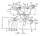
- FIG. 1 is a left side view of a cassette loading device according to the present invention after assembly.
- the cassette loading device shown in FIG. 1 is in a state where a user can insert or remove a cassette to or from the body of the cassette loading device.
- FIG. 2 is a top view of the cassette loading device of FIG. 1 .
- FIG. 3 is a magnified top view showing a primary part of the cassette loading device of FIG. 1 .
- FIG. 4 is another left side view of the cassette loading device of FIG. 1 .
- the cassette loading device shown in FIG. 4 is in a state where a cassette has been loaded into the body of the magnetic recording/reproducing apparatus.
- a “near side” refers to a first position in a direction shown with arrow A in FIGS. 1 , 4 , 5 and 6
- a “far side” refers to a second position in a direction shown with arrow B in the same figures.
- reference numerals 1 , 2 and 3 respectively denote a cassette including a (magnetic) tape, a body sidewall of a body of a magnetic recording/reproducing apparatus, and a holder.
- the body sidewall 2 includes a body support hole 2 a (first body engagement member), a body slot 2 b (second body engagement member), a guide slit 2 c , and a receiving portion 2 d .
- the body slot 2 b includes an enlarged hole 2 e on its far side.
- the receiving portion 2 d includes an inclined face 2 f on the back side thereof (corresponding to the reverse side of the sheet of FIG. 1 ).
- the holder 3 retains the cassette 1 therein and includes a holder support hole 3 a (first holder engagement member) and a holder slot 3 b (second holder engagement member). Although a ceiling portion or the like, which defines an uppermost position of the cassette loading device, is located above the holder 3 , such a portion is omitted in the drawings for clarity of illustration.
- Reference numeral 4 denotes a main arm which includes: a first main arm support hole 4 a (first main arm engagement member) and a spring hanger hole 4 b at the near side; a second main arm support hole 4 c substantially at the center of the main arm 4 ; and a main arm pin 5 -(second main arm engagement member) at the far side.
- the main arm pin 5 is engaged with the body slot 2 b in a slidable manner.
- the main arm pin 5 includes a base 5 a and a flange 5 b having a diameter larger than that of the base 5 a .
- a slot width of the body slot 2 b is larger than the diameter of the base 5 a and smaller than the diameter of the flange 5 b .
- the enlarged hole 2 e has a diameter larger than that of the flange 5 b .
- Reference numeral 6 denotes a synchronous shaft which is positioned in the first main arm support hole 4 a and is fixed so as not to be rotated with respect to the main arm 4 .
- the synchronous shaft 6 is also positioned in a support hole in a main arm 10 (shown in FIG. 2 ) provided on the other side (right side view) of the body and is fixed in a similar manner.
- the synchronous shaft 6 passes through the holder support hole 3 a and is supported with respect to the holder 3 in a rotatable manner.
- the main arm 10 is also rotated at the same angle as the rotation angle of the main arm 4 , thereby ensuring that the left and right holder retention mechanisms move in synchronization with each other.
- Reference numeral 7 denotes a subarm which includes: a first subarm pin 8 a (second subarm engagement member) and a spring hanger 7 a at the far side; a second subarm pin 8 b substantially at the center of the subarm 7 ; and a third subarm pin 8 c (first subarm engagement member) and a press portion 7 b on the near side.
- the first subarm pin 8 a is engaged with the holder slot 3 b in a slidable manner.
- the second subarm pin 8 b is engaged with the second main arm support hole 4 c in a rotatable manner.
- the third subarm pin 8 c is engaged with the body support hole 2 a in a rotatable manner.
- the subarm 7 has a guide 7 c and a near side portion 7 d .
- the body sidewall 2 is sandwiched between the near side portion 7 d and the guide 7 c .
- the subarm 7 can be elastically deformed in a direction normal to the elongated length thereof about the rotation center thereof.
- Reference numeral 9 denotes a spring having one end joined to the spring hanger 7 a and another end joined to the spring hanger hole 4 b so as to be connected between the main arm 4 and the subarm 7 .
- the holder 3 is retained by the main arm 4 and the subarm 7 so as to move up and down. Motion trajectories of the main arm 4 and the subarm 7 cause the holder 3 to be maintained in a substantially horizontal manner in relation to the body even when the holder 3 is moved up and down.
- the spring 9 biases the main arm 4 so as to be rotated counterclockwise and also biases the subarm 7 so as to be rotated clockwise, so that the holder 3 is always biased so as to move upward (i.e., away from the body), when it is desired to move the holder from the lowermost position thereof.
- the holder 3 is in an uppermost position of its moving range. In this state, a user can insert the cassette 1 into the holder 3 and remove the cassette 1 from the holder 3 .
- the holder 3 is in a lowermost position of its moving range. In this state, the cassette 1 is loaded into the body, such that the tape in the cassette 1 is in a recordable and reproduceable state. It should be noted that none of the drawings show a lock mechanism for retaining the cassette loading device in the state shown in FIG. 4 , however such lock mechanisms are known.
- the main arm 10 on the right side of the body which is connected to the main arm 4 via the synchronous shaft 6 , is also rotated at the same angle as the rotation angle of the main arm 4 , thereby ensuring that the left and right mechanisms move in synchronization with each other. That is, the holder 3 can move up and down while in a substantially horizontal manner with respect to the body such that neither the right nor left sides of the holder is at a level substantially higher than the other side.
- FIGS. 5 and 6 respectively illustrate a left side view of the cassette loading device according to the present invention during different steps of assembly.
- FIG. 7 is a magnified top view showing a primary part of the cassette loading device during assembly.
- the arm pin 5 is aligned with the enlarged hole 2 e in the body slot 2 b , and the flange 5 b of the main arm pin 5 is passed through the enlarged hole 2 e in a normal direction from the reverse of the sheet of FIG. 5 to the front face of the sheet. This is also done for the right side of the cassette loading device and body of the magnetic recording/reproducing apparatus.
- the main arm pin 5 By sliding the main arm pin 5 to the near side of the body slot 2 b , it is possible to engage the main arm pin 5 with the body slot 2 b .
- the cassette loading device is rotated clockwise about a pivot provided by the main arm pin 5 such that the cassette loading device is shifted to a position shown in FIG. 6 . In this position, the body sidewall 2 is sandwiched between the near side portion 7 d and the guide 7 c of the subarm 7 , and the third subarm pin 8 c is forced to come into contact with the receiving portion 2 d of the body.
- the third pin 8 c is moved so as to slide on the inclined face 2 f of the receiving portion 2 d .
- the subarm 7 is made to move along a direction shown by arrow C, the subarm 7 is not allowed to move since the right side of the guide 7 a is forced to come into contact with the left side surface of the body sidewall 2 .
- the near side portion 7 d of the subarm 7 is elastically deformed, and the third subarm pin 8 c is moved along the direction shown by arrow C by sliding along the inclined surface 2 f so as to provide partial engagement of the third subarm pin 8 c and the body, in which state the guide 7 c is at least partially accommodated in the guide slot 2 c of the body. That is, the third subarm pin 8 c is moved along a direction of a rotation center axis of the subarm 7 .
- the third subarm pin 8 c is aligned with the body support hole 2 a , as shown in FIG. 3 , where the elastically-deformed subarm 7 returns to its original state. This causes the subarm third pin 8 c to fit into the body support hole 2 a , thereby being engaged with the body support hole 2 a.
- FIG. 1 illustrates complete assemblage of the cassette loading device assembled with body sidewall 2 .
- the main arm pin 5 never moves to a position of the enlarged hole 2 e over a moving range of the cassette loading device. Accordingly, after assembly, the main arm pin 5 is not disengaged from the body slot 2 b . Thus, it is not necessary to cover the large hole 2 e , of the body slot 2 b to maintain engagement of the main arm pin 5 with the body slot 2 b during operation of the cassette loading device of the present invention.
- a cassette loading device includes: a holder for retaining a cassette therein, the holder reciprocating between a first holder position for insertion of the cassette (e.g., a cassette including a (magnetic) tape therein) into the holder and a second holder position for loading the cassette into a body (e.g., the body of a magnetic recording/reproducing apparatus); a main arm including a first main arm engagement member provided at one end of the main arm for engagement with a first holder engagement member provided at a first position of a side face of the holder such that the main arm is rotatable about the first main arm engagement member, and a second main arm engagement member provided at another end of the main arm for engagement with a second body engagement member provided at a second position of the body such that the main arm is slidable along the second body engagement member; and a subarm including a first subarm engagement member provided at one end of the subarm for engagement with a first body engagement member provided at a first position
- the subarm is supported at a rotation center thereof so as to be rotatable with respect to a rotation center on the main arm.
- the first subarm engagement member is elastically deformed so that the first subarm engagement member is moved along a direction of a rotation center axis of the subarm so that the first subarm engagement member is disengaged from the first body engagement member.
Landscapes
- Automatic Tape Cassette Changers (AREA)
- Feeding And Guiding Record Carriers (AREA)
Abstract
Description
Claims (4)
Applications Claiming Priority (2)
| Application Number | Priority Date | Filing Date | Title |
|---|---|---|---|
| JP2001190989A JP2003006960A (en) | 2001-06-25 | 2001-06-25 | Cassette mounting device |
| JP2001-190989 | 2001-06-25 |
Publications (2)
| Publication Number | Publication Date |
|---|---|
| US20020196579A1 US20020196579A1 (en) | 2002-12-26 |
| US6867945B2 true US6867945B2 (en) | 2005-03-15 |
Family
ID=19029679
Family Applications (1)
| Application Number | Title | Priority Date | Filing Date |
|---|---|---|---|
| US10/159,740 Expired - Fee Related US6867945B2 (en) | 2001-06-25 | 2002-05-31 | Cassette loading device |
Country Status (2)
| Country | Link |
|---|---|
| US (1) | US6867945B2 (en) |
| JP (1) | JP2003006960A (en) |
Families Citing this family (3)
| Publication number | Priority date | Publication date | Assignee | Title |
|---|---|---|---|---|
| KR20050120164A (en) * | 2004-06-18 | 2005-12-22 | 삼성전자주식회사 | Lever fixing apparatus of cassette housing and magnetic recording and reproducing apparatus having the same |
| JP6097929B2 (en) * | 2013-01-17 | 2017-03-22 | パナソニックIpマネジメント株式会社 | refrigerator |
| CN105650082B (en) * | 2016-03-23 | 2017-09-29 | 广西大学 | A kind of self-locking structure |
Citations (5)
| Publication number | Priority date | Publication date | Assignee | Title |
|---|---|---|---|---|
| US6038100A (en) * | 1994-08-06 | 2000-03-14 | Canon Kabushiki Kaisha | Recording and/or reproducing apparatus with variably damped cassette loading mechanism |
| US6072658A (en) * | 1995-03-22 | 2000-06-06 | Canon Kabushiki Kaisha | Cassette mounting device having link mechanism arranged to support cassette holder |
| US6115209A (en) * | 1997-03-12 | 2000-09-05 | Matsushita Electric Industrial Co., Ltd. | Cassette loading device |
| US6198596B1 (en) * | 1997-08-22 | 2001-03-06 | Canon Kabushiki Kaisha | Cassette mounting device having lock lever spring disposed in cassette holder |
| US20010012173A1 (en) * | 2000-01-25 | 2001-08-09 | Kiyoshi Kumagai | Cassette loading apparatus |
Family Cites Families (1)
| Publication number | Priority date | Publication date | Assignee | Title |
|---|---|---|---|---|
| JPS578665U (en) * | 1980-06-18 | 1982-01-16 |
-
2001
- 2001-06-25 JP JP2001190989A patent/JP2003006960A/en active Pending
-
2002
- 2002-05-31 US US10/159,740 patent/US6867945B2/en not_active Expired - Fee Related
Patent Citations (5)
| Publication number | Priority date | Publication date | Assignee | Title |
|---|---|---|---|---|
| US6038100A (en) * | 1994-08-06 | 2000-03-14 | Canon Kabushiki Kaisha | Recording and/or reproducing apparatus with variably damped cassette loading mechanism |
| US6072658A (en) * | 1995-03-22 | 2000-06-06 | Canon Kabushiki Kaisha | Cassette mounting device having link mechanism arranged to support cassette holder |
| US6115209A (en) * | 1997-03-12 | 2000-09-05 | Matsushita Electric Industrial Co., Ltd. | Cassette loading device |
| US6198596B1 (en) * | 1997-08-22 | 2001-03-06 | Canon Kabushiki Kaisha | Cassette mounting device having lock lever spring disposed in cassette holder |
| US20010012173A1 (en) * | 2000-01-25 | 2001-08-09 | Kiyoshi Kumagai | Cassette loading apparatus |
Also Published As
| Publication number | Publication date |
|---|---|
| US20020196579A1 (en) | 2002-12-26 |
| JP2003006960A (en) | 2003-01-10 |
Similar Documents
| Publication | Publication Date | Title |
|---|---|---|
| EP0504859B1 (en) | Cassette loading apparatus | |
| JP3387789B2 (en) | Tray loading mechanism of recording / reproducing device | |
| EP0944083A1 (en) | Recording medium cartridge with spring-biased shutter | |
| US6867945B2 (en) | Cassette loading device | |
| US6456582B1 (en) | Apparatus for chucking a cartridge having a position restricting mechanism | |
| KR0176551B1 (en) | Magnetic recording / playback device | |
| JP4103435B2 (en) | Tape guide mechanism of magnetic recording / reproducing apparatus | |
| EP0431914B1 (en) | Magnetic tape cassettes | |
| JP2899780B2 (en) | Cassette holder device | |
| EP0411670A2 (en) | Disk cartridge | |
| JPS6364821B2 (en) | ||
| JPH0437325Y2 (en) | ||
| US4807215A (en) | Floppy disc loading apparatus | |
| JPH0441485Y2 (en) | ||
| US5768048A (en) | Tape cassette cover opening and closing device | |
| JP2002170305A (en) | Cassette mounting device | |
| JPH0531702Y2 (en) | ||
| KR830002732Y1 (en) | Tape recorder | |
| JP2623637B2 (en) | Cassette loading device | |
| JPH0734528Y2 (en) | Disk cassette mounting device | |
| JPH0765462A (en) | Loading device for tape cassette | |
| JPH0124775Y2 (en) | ||
| JPH04289552A (en) | Cassette loader | |
| JPH0773566A (en) | Cartridge leading-in device | |
| JPH11213487A (en) | Unlocking mechanism of cassette front cover for cassette loading device |
Legal Events
| Date | Code | Title | Description |
|---|---|---|---|
| AS | Assignment |
Owner name: MATSUSHITA ELECTRIC INDUSTRIAL CO., LTD., JAPAN Free format text: ASSIGNMENT OF ASSIGNORS INTEREST;ASSIGNORS:IWASAKI, KEISHI;KONISHI, AKIO;REEL/FRAME:012957/0033 Effective date: 20020419 |
|
| FEPP | Fee payment procedure |
Free format text: PAYOR NUMBER ASSIGNED (ORIGINAL EVENT CODE: ASPN); ENTITY STATUS OF PATENT OWNER: LARGE ENTITY |
|
| FPAY | Fee payment |
Year of fee payment: 4 |
|
| FEPP | Fee payment procedure |
Free format text: PAYOR NUMBER ASSIGNED (ORIGINAL EVENT CODE: ASPN); ENTITY STATUS OF PATENT OWNER: LARGE ENTITY Free format text: PAYER NUMBER DE-ASSIGNED (ORIGINAL EVENT CODE: RMPN); ENTITY STATUS OF PATENT OWNER: LARGE ENTITY |
|
| FPAY | Fee payment |
Year of fee payment: 8 |
|
| REMI | Maintenance fee reminder mailed | ||
| LAPS | Lapse for failure to pay maintenance fees | ||
| STCH | Information on status: patent discontinuation |
Free format text: PATENT EXPIRED DUE TO NONPAYMENT OF MAINTENANCE FEES UNDER 37 CFR 1.362 |
|
| STCH | Information on status: patent discontinuation |
Free format text: PATENT EXPIRED DUE TO NONPAYMENT OF MAINTENANCE FEES UNDER 37 CFR 1.362 |
|
| FP | Lapsed due to failure to pay maintenance fee |
Effective date: 20170315 |