US6853472B2 - Electrolytes for electrooptic devices comprising ionic liquids - Google Patents
Electrolytes for electrooptic devices comprising ionic liquids Download PDFInfo
- Publication number
- US6853472B2 US6853472B2 US10/600,807 US60080703A US6853472B2 US 6853472 B2 US6853472 B2 US 6853472B2 US 60080703 A US60080703 A US 60080703A US 6853472 B2 US6853472 B2 US 6853472B2
- Authority
- US
- United States
- Prior art keywords
- structural formula
- independently
- bridge
- alkyl
- imide
- Prior art date
- Legal status (The legal status is an assumption and is not a legal conclusion. Google has not performed a legal analysis and makes no representation as to the accuracy of the status listed.)
- Expired - Lifetime, expires
Links
- 0 [3*][N+]1(C)CCCC1 Chemical compound [3*][N+]1(C)CCCC1 0.000 description 36
- VFQJMARQPNUHLA-UHFFFAOYSA-N CC(C(C(N)=C(C1=N)N)=N)=C1N Chemical compound CC(C(C(N)=C(C1=N)N)=N)=C1N VFQJMARQPNUHLA-UHFFFAOYSA-N 0.000 description 1
- BBQCFWYJYBWYDF-UHFFFAOYSA-N CC.CC.OC1=C(N2N=C3C=CC=CC3=N2)C=CC=C1 Chemical compound CC.CC.OC1=C(N2N=C3C=CC=CC3=N2)C=CC=C1 BBQCFWYJYBWYDF-UHFFFAOYSA-N 0.000 description 1
- VBHBZVSEBMMFRL-UHFFFAOYSA-N CCCCC(CC)C[N+]1=CC=C(C2=CC=[N+](C(=O)[O-])C=C2)C=C1.O=S(=O)([N-]S(=O)(=O)C(F)(F)F)C(F)(F)F Chemical compound CCCCC(CC)C[N+]1=CC=C(C2=CC=[N+](C(=O)[O-])C=C2)C=C1.O=S(=O)([N-]S(=O)(=O)C(F)(F)F)C(F)(F)F VBHBZVSEBMMFRL-UHFFFAOYSA-N 0.000 description 1
- GTAXSEAXYGDXRU-UHFFFAOYSA-N CCCCC(CC)C[N+]1=CC=C(C2=CC=[N+](CC(=O)O[Eu])C=C2)C=C1.O=S(=O)([N-]S(=O)(=O)C(F)(F)F)C(F)(F)F Chemical compound CCCCC(CC)C[N+]1=CC=C(C2=CC=[N+](CC(=O)O[Eu])C=C2)C=C1.O=S(=O)([N-]S(=O)(=O)C(F)(F)F)C(F)(F)F GTAXSEAXYGDXRU-UHFFFAOYSA-N 0.000 description 1
- ILTQOTFNHPFZIP-UHFFFAOYSA-N CS(=O)(=O)[N-]S(=O)(=O)C(F)(F)F Chemical compound CS(=O)(=O)[N-]S(=O)(=O)C(F)(F)F ILTQOTFNHPFZIP-UHFFFAOYSA-N 0.000 description 1
- NUNIPPYORIVCKW-UHFFFAOYSA-N CS1(CCCC1)N=C Chemical compound CS1(CCCC1)N=C NUNIPPYORIVCKW-UHFFFAOYSA-N 0.000 description 1
- PDWGJFDOLSGHGX-UHFFFAOYSA-N C[N+]1=CC=C(C2=CC=[N+](C)C=C2)C=C1.[BH4-] Chemical compound C[N+]1=CC=C(C2=CC=[N+](C)C=C2)C=C1.[BH4-] PDWGJFDOLSGHGX-UHFFFAOYSA-N 0.000 description 1
- NHHWJSXMTZIPES-UHFFFAOYSA-N O=S(C(F)(F)F)([N-]S(C(F)(F)F)(=O)=O)=O Chemical compound O=S(C(F)(F)F)([N-]S(C(F)(F)F)(=O)=O)=O NHHWJSXMTZIPES-UHFFFAOYSA-N 0.000 description 1
Images


Classifications
-
- C—CHEMISTRY; METALLURGY
- C09—DYES; PAINTS; POLISHES; NATURAL RESINS; ADHESIVES; COMPOSITIONS NOT OTHERWISE PROVIDED FOR; APPLICATIONS OF MATERIALS NOT OTHERWISE PROVIDED FOR
- C09B—ORGANIC DYES OR CLOSELY-RELATED COMPOUNDS FOR PRODUCING DYES, e.g. PIGMENTS; MORDANTS; LAKES
- C09B57/00—Other synthetic dyes of known constitution
-
- C—CHEMISTRY; METALLURGY
- C07—ORGANIC CHEMISTRY
- C07C—ACYCLIC OR CARBOCYCLIC COMPOUNDS
- C07C311/00—Amides of sulfonic acids, i.e. compounds having singly-bound oxygen atoms of sulfo groups replaced by nitrogen atoms, not being part of nitro or nitroso groups
- C07C311/48—Amides of sulfonic acids, i.e. compounds having singly-bound oxygen atoms of sulfo groups replaced by nitrogen atoms, not being part of nitro or nitroso groups having nitrogen atoms of sulfonamide groups further bound to another hetero atom
-
- C—CHEMISTRY; METALLURGY
- C07—ORGANIC CHEMISTRY
- C07C—ACYCLIC OR CARBOCYCLIC COMPOUNDS
- C07C317/00—Sulfones; Sulfoxides
- C07C317/02—Sulfones; Sulfoxides having sulfone or sulfoxide groups bound to acyclic carbon atoms
- C07C317/04—Sulfones; Sulfoxides having sulfone or sulfoxide groups bound to acyclic carbon atoms of an acyclic saturated carbon skeleton
-
- C—CHEMISTRY; METALLURGY
- C07—ORGANIC CHEMISTRY
- C07D—HETEROCYCLIC COMPOUNDS
- C07D213/00—Heterocyclic compounds containing six-membered rings, not condensed with other rings, with one nitrogen atom as the only ring hetero atom and three or more double bonds between ring members or between ring members and non-ring members
- C07D213/02—Heterocyclic compounds containing six-membered rings, not condensed with other rings, with one nitrogen atom as the only ring hetero atom and three or more double bonds between ring members or between ring members and non-ring members having three double bonds between ring members or between ring members and non-ring members
- C07D213/04—Heterocyclic compounds containing six-membered rings, not condensed with other rings, with one nitrogen atom as the only ring hetero atom and three or more double bonds between ring members or between ring members and non-ring members having three double bonds between ring members or between ring members and non-ring members having no bond between the ring nitrogen atom and a non-ring member or having only hydrogen or carbon atoms directly attached to the ring nitrogen atom
- C07D213/06—Heterocyclic compounds containing six-membered rings, not condensed with other rings, with one nitrogen atom as the only ring hetero atom and three or more double bonds between ring members or between ring members and non-ring members having three double bonds between ring members or between ring members and non-ring members having no bond between the ring nitrogen atom and a non-ring member or having only hydrogen or carbon atoms directly attached to the ring nitrogen atom containing only hydrogen and carbon atoms in addition to the ring nitrogen atom
- C07D213/22—Heterocyclic compounds containing six-membered rings, not condensed with other rings, with one nitrogen atom as the only ring hetero atom and three or more double bonds between ring members or between ring members and non-ring members having three double bonds between ring members or between ring members and non-ring members having no bond between the ring nitrogen atom and a non-ring member or having only hydrogen or carbon atoms directly attached to the ring nitrogen atom containing only hydrogen and carbon atoms in addition to the ring nitrogen atom containing two or more pyridine rings directly linked together, e.g. bipyridyl
-
- G—PHYSICS
- G02—OPTICS
- G02F—OPTICAL DEVICES OR ARRANGEMENTS FOR THE CONTROL OF LIGHT BY MODIFICATION OF THE OPTICAL PROPERTIES OF THE MEDIA OF THE ELEMENTS INVOLVED THEREIN; NON-LINEAR OPTICS; FREQUENCY-CHANGING OF LIGHT; OPTICAL LOGIC ELEMENTS; OPTICAL ANALOGUE/DIGITAL CONVERTERS
- G02F1/00—Devices or arrangements for the control of the intensity, colour, phase, polarisation or direction of light arriving from an independent light source, e.g. switching, gating or modulating; Non-linear optics
- G02F1/01—Devices or arrangements for the control of the intensity, colour, phase, polarisation or direction of light arriving from an independent light source, e.g. switching, gating or modulating; Non-linear optics for the control of the intensity, phase, polarisation or colour
- G02F1/15—Devices or arrangements for the control of the intensity, colour, phase, polarisation or direction of light arriving from an independent light source, e.g. switching, gating or modulating; Non-linear optics for the control of the intensity, phase, polarisation or colour based on an electrochromic effect
- G02F1/1503—Devices or arrangements for the control of the intensity, colour, phase, polarisation or direction of light arriving from an independent light source, e.g. switching, gating or modulating; Non-linear optics for the control of the intensity, phase, polarisation or colour based on an electrochromic effect caused by oxidation-reduction reactions in organic liquid solutions, e.g. viologen solutions
-
- G—PHYSICS
- G02—OPTICS
- G02F—OPTICAL DEVICES OR ARRANGEMENTS FOR THE CONTROL OF LIGHT BY MODIFICATION OF THE OPTICAL PROPERTIES OF THE MEDIA OF THE ELEMENTS INVOLVED THEREIN; NON-LINEAR OPTICS; FREQUENCY-CHANGING OF LIGHT; OPTICAL LOGIC ELEMENTS; OPTICAL ANALOGUE/DIGITAL CONVERTERS
- G02F1/00—Devices or arrangements for the control of the intensity, colour, phase, polarisation or direction of light arriving from an independent light source, e.g. switching, gating or modulating; Non-linear optics
- G02F1/01—Devices or arrangements for the control of the intensity, colour, phase, polarisation or direction of light arriving from an independent light source, e.g. switching, gating or modulating; Non-linear optics for the control of the intensity, phase, polarisation or colour
- G02F1/15—Devices or arrangements for the control of the intensity, colour, phase, polarisation or direction of light arriving from an independent light source, e.g. switching, gating or modulating; Non-linear optics for the control of the intensity, phase, polarisation or colour based on an electrochromic effect
- G02F1/1514—Devices or arrangements for the control of the intensity, colour, phase, polarisation or direction of light arriving from an independent light source, e.g. switching, gating or modulating; Non-linear optics for the control of the intensity, phase, polarisation or colour based on an electrochromic effect characterised by the electrochromic material, e.g. by the electrodeposited material
- G02F2001/15145—Devices or arrangements for the control of the intensity, colour, phase, polarisation or direction of light arriving from an independent light source, e.g. switching, gating or modulating; Non-linear optics for the control of the intensity, phase, polarisation or colour based on an electrochromic effect characterised by the electrochromic material, e.g. by the electrodeposited material the electrochromic layer comprises a mixture of anodic and cathodic compounds
Definitions
- the present invention relates generally to electrolyte solutions and electrooptic devices and more particularly to electrolyte solutions of UV stabilizing dyes in ionic liquid solvents and to electrooptic devices employing these solutions.
- Electrooptic devices are devices in which an applied electrical voltage produces a change in the optical properties of the device. Electrooptic devices are used for many applications such as variable transmission windows used for management of solar heat gain in buildings and variable transmission automotive mirrors.
- a specific type of an electrooptic device is an electrochromic device, i.e. a device that changes color in response to an applied voltage.
- Electrochromic (EC) devices provide reversible modulation of light and are useful for several applications. Some of the applications are rearview mirrors for automobiles, trucks, buses, scooters and motorcycles; windows for automobiles, other transportation (including road, rail, water and air) and buildings, eyewear and attenuation or modulation of artificial lighting, displays, contrast enhancement filters (including variable transmission filters for helmet mounted displays). The only successful commercial application thus far has been for automotive rearview mirrors. High cost and lack of durability have limited commercial window applications of these EC devices.
- the durability limitation of the EC devices arises in part due to the electrolytes and solvents used in the prior art.
- the typical high dielectric solvents used in present day devices may have one or more of the following drawbacks: high volatility, high moisture sensitivity, hydrophilicity, a narrow range of electrochemical stability, chemical reactivity, and susceptibility to light-induced degradation (typically from ultraviolet or UV light).
- One of the requirements of solvents for EC devices is that the other chemical components of the EC device are soluble and chemically stable with them.
- ionic liquids for electrooptic devices
- many of the known components of electrochromic devices have limited solubility in ionic liquids.
- the intrinsic limitations, e.g. electrochemical stability, of known electrochromic dyes and additives are matched to conventional organic solvents, and therefore these dyes and other additives do not allow the full exploitation of the advantageous properties of the ionic liquids.
- the use of ionic liquids is described, for example, in PCT Patent Application WO 01/93363 to A. McEwen et al. entitled “Non-Flammable Electrolytes,” in Japanese Patent 98168028 to M. Watanabe et al.
- an object of the present invention is to provide an electrooptic device with greater durability.
- Another object of the present invention is to provide electrolyte solutions for electrooptic devices.
- Still another object of the invention is to provide soluble dye compounds for use with ionic liquids for electrooptic devices.
- the present invention includes an electrolyte solution having a Tg of less than about ⁇ 40° C. that includes at least one bifunctional redox dye compound dissolved in an ionic liquid solvent.
- redox dye compound useful with the invention includes a redox active anodic moiety and a redox active cathodic moiety.
- Another type of redox dye compound includes an energy receptor moiety and either a redox active anodic moiety or a redox active cathodic moiety.
- Preferred cations of the ionic liquid solvent include lithium cation and quaternary ammonium cations, where preferred quaternary ammonium cations are pyridinium, pyridazinium, pyrimidinium, pyrazinium, imidazolium, pyrazolium, thiazolium, oxazolium, triazolium, tetraalkylammonium, N-methyl morpholinium, cations of the formula [(CH 3 CH 2 ) 3 N(R 1 )] + , wherein R 1 is alkyl having 2-10 carbons, cations of the formula [(CH 3 ) 2 (CH 3 CHCH 3 )N(R 2 )] + , wherein R 2 is alkyl having 2-10 carbons, cations having the structural formula wherein R 3 is alkyl having 2-10 carbons, and cations having the structural formula wherein R 4 is alkyl having 2-10 carbons, and preferred anions include trifluoromethyl
- the invention also includes an electro-optic device having at least one chamber and, as the electrolyte medium inside the chamber, an electrolyte solution of a bifunctional redox dye compound dissolved in ionic liquid solvent and having a Tg of less than about ⁇ 40° C.
- a bifunctional redox dye compound useful with the invention includes a redox active anodic moiety and a redox active cathodic moiety.
- Another type of redox dye compound includes an energy receptor moiety and either a redox active anodic moiety or a redox active cathodic moiety.
- Preferred cations of the ionic liquid solvent include lithium cation and quaternary ammonium cations, where preferred quaternary ammonium cations include pyridinium, pyridazinium, pyrimidinium, pyrazinium, imidazolium, pyrazolium, thiazolium, oxazolium, triazolium, tetraalkylammonium, N-methyl morpholinium, cations of the formula [(CH 3 CH 2 ) 3 N(R 1 )] + , wherein R 1 is alkyl having 2-10 carbons, cations of the formula [(CH 3 ) 2 (CH 3 CHCH 3 )N(R 2 )] + , wherein R 2 is alkyl having 2-10 carbons, cations having the structural formula wherein R 3 is alkyl having 2-10 carbons, and cations having the structural formula wherein R 4 is alkyl having 2-10 carbons, and preferred anions include trifluoromethyl
- the invention also includes dye compounds for use with electrooptic devices.
- the invention also includes a method for filling an empty electrooptic device with warm ionic liquid electrolyte solution, the device having relatively closely spaced plates, each plate having an inwardly facing conductive surface, the plates being sealed around their periphery by a seal that encloses an area of each plate.
- the method involves introducing a small opening into the seal of an empty device and placing the empty device into a chamber along with a container of an electrolyte solution that includes ionic liquid solvent. After evacuating the chamber, the empty device is lowered into the electrolyte solution such that the opening in the seal is located under the surface of the solution. At least a portion of the electrolyte solution is warmed to at least 40° C. Upon exposure of the solution to gas pressure greater than the pressure in the empty device, the warm electrolyte solution moves into the device. After filling the device with electrolyte solution, the gap is sealed.
- FIG. 1 a shows a cutaway, edge-on view of an embodiment of an electrochromic device of the invention
- FIG. 1 b shows a perspective view of the embodiment of the electrochromic device of FIG. 1 a;
- FIG. 2 shows a cutaway, edge-on view of an embodiment of an electrochromic device of the invention that includes an electrochemically active coating
- FIG. 3 shows a cutaway, edge-on view of an embodiment of an electrochromic device of the invention that includes an electrochemically active coating and an ion-selective transport layer;
- FIG. 4 shows a cutaway, edge-on view of an embodiment of an electrochromic device of the invention that includes two electrochemically active coatings;
- FIGS. 5 a-c show a schematic representation for a vacuum-backfill process
- FIG. 6 shows the absorption spectra of several solvents
- FIG. 7 shows the transmission spectra of an electrochromic device that includes redox dyes in the electrolyte in colored and the bleached state
- FIG. 8 shows a kinetic trace of an electrochromic device containing redox dyes in the electrolyte
- FIG. 9 shows transmission spectra of an electrochromic device that includes a layer of tungsten oxide in colored and the bleached state
- FIG. 10 shows the method for measuring the distance between the busbars of an embodiment of the present invention
- FIG. 11 shows a graph of data used to determine the Tg of an ionic liquid and a solution of an ionic liquid and a non-ionic liquid
- FIG. 12 shows another graph of data used to determine the Tg of an ionic liquid and a solution of an ionic liquid and a non-ionic liquid
- FIG. 13 shows the absorption spectra of a charge transfer complex and of the individual components
- FIG. 14 shows a cyclic voltammogram of the charge transfer complex between 5,10-dihydro-5,10-dimethylphenazine and N,N′-diethylviologen bis(trifluoromethanesulfonyl)imide in N-butyl-N-methylpyrrolidinium bis(trifluoromethylsulfonyl)imide.
- the invention relates to electrooptic devices that employ ionic liquids as electrolyte solvents.
- Ionic liquids are molten salts that have melting points at or below room temperature.
- the terms “ionic liquid” and “molten salt” have the same meaning.
- a non-exhaustive list of these materials is provided by R. Hagiwara and Y. Ito in “Room Temperature Ionic Liquids of Alkylimidazolium Cations and Fluoroanions”, J. Fluorine Chem. vol. 105, (2000), pp. 221-227.
- Ionic liquid solvents of this invention do not include the mineral acids (such as sulfuric acid).
- the present invention relates to electrolytes and other components and constructions of EC devices using ionic liquids as solvents.
- the present invention relates to employing ionic liquid solvents in display devices, where individual electrodes allow pictures, words, and other images to be created and controlled through EC behavior. Processing methods are disclosed for manufacturing electrooptic devices.
- ionic liquid solvents can offer several benefits, which include a wider range for electrochemical stability (greater than 4V and in some cases greater than 6V); high hydrophobicity; a high decomposition temperature (ionic liquids used with the invention do not boil but they decompose, the decomposition temperatures should be higher than 150° C. and more preferably higher than 200° C.); a negligible vapor pressure (see, for example, C. M. Gordon in “New developments in catalysis using ionic liquids, Applied Catalysis: General A, vol. 222, (2001) pp. 101-117; and J. M. Earle in “Diels-Alder Reactions in Ionic Liquids,” Green Chemistry, vol.
- Ionic liquid solvents useful with the invention include salts of organic cations in combination with either organic or inorganic anions.
- Preferred anions of the invention contain fluorine, and include trifluoromethylsulfonate (“triflate,” CF 3 SO 3 ⁇ ), bis(trifluoromethylsulfonyl)imide (N(CF 3 SO 2 ) 2 ⁇ ), bis(perfluoroethylsulfonyl)imide ((C 2 F 5 SO 2 ) 2 N ⁇ )), tris(trifluoromethylsulfonyl)methide ((CF 3 SO 2 ) 3 C ⁇ )), tetrafluoroborate (BF 4 ⁇ ), hexafluorophosphate (PF 6 ⁇ ), hexafluoroantimonate (SbF 6 ⁇ ), and hexafluoroarsenate (AsF 6 ⁇ ).
- triflate CF 3 SO 3 ⁇
- trifluoromethylsulfonate (“triflate,” CF 3 SO 3 ⁇ ), bis(trifluoromethylsulfonyl)imide (N(CF 3 SO 2 ) 2 ⁇ ), bis(perfluoroethylsulfonyl)imide ((C 2 F 5 SO 2 ) 2 N ⁇ )), tris(trifluoromethylsulfonyl)methide ((CF 3 SO 2 ) 3 C ⁇ )) are preferred.
- the most preferred anion is bis(trifluoromethylsulfonyl)imide anion (N(CF 3 SO 2 ) 2 ⁇ ) because of its low cost and high hydrophobicity.
- the bis(trifluoromethylsulfonyl)imide anion is sometimes referred to in the prior art as bis(trifluoromethanesulfonyl)amide or bis(trifluoromethanesulfonyl)imide, and has the structural formula
- Preferred organic cations of molten salts used with the invention include, but are not limited to, pyridinium, pyridazinium, pyrimidinium, pyrazinium, imidazolium, pyrazolium, thiazolium, oxazolium, and triazolium.
- a preferred list of quaternary ammonium based ionic liquids are all those with a glass transition temperature (T g ) lower than ⁇ 40° C. given in Table 1 of the publication by J. Sun, M. Forsyth, and D. R. MacFarlane entitled “Room-Temperature Molten Salts Based on the Quaternary Ammonium Ion,” J. Phys. Chem. B, 1998, vol.
- Preferred ionic liquids include tetraalkylammonium cations because ionic liquids made from these cations have minimal optical absorbance in the ultraviolet portion of the spectrum, which gives molten salts based on these cations enhanced photochemical stability (see, J. Sun et al., vide supra).
- Quaternary ammonium cations useful with the invention may be substituted with H, F, phenyl, alkyl groups with 1 to 15 carbon atoms, and other chemical substituents. Cations may even have bridged ring structures.
- Most preferred quaternary ammonium cations have the formula (CH 3 CH 2 ) 3 N(R 1 ), wherein R 1 is alkyl having 2-10 carbons; or have the formula (CH 3 ) 2 (CH 3 CHCH 3 )N(R 2 ), wherein R 2 is alkyl having 2-10 carbons; or have the structural formula wherein R 3 is alkyl having 2-10 carbons; or have the structural formula wherein R 4 is alkyl having 2-10 carbons.
- the ionic liquid solvent is N-butyl-N-methylpyrrolidinium bis(trifluoromethylsulfonyl)imide.
- the high electrochemical stability window assures that the even when the electrochemical potentials for reducing or oxidizing EC materials change with temperature, they will be within the stability window of the ionic liquid solvent.
- High hydrophobicity ensures that water does not become an integral part of the electrolyte and generate electrochemical reactions that are not reversible.
- High boiling points and low vapor pressures of ionic liquids are useful properties from the electrooptic device fabrication perspective. Most of the EC devices are backfilled in vacuum (the vacuum backfill process is described in detail later). The low vapor pressure does not contaminate the vacuum systems, keeps the electrolyte composition constant and does not entrap bubbles in the filling process. This also enhances chemical safety in the work place. Low flammability is important from a safety perspective, particularly when used in buildings and in transportation.
- Preferred ionic liquid solvents used with the present invention do not significantly absorb ultraviolet radiation having a wavelength above 290 nanometers (nm), and therefore do not degrade when exposed to these wavelengths to byproducts that can lead to irreversible coloration, gas formation and/or formation of electrochemically active/inactive species.
- the preferred ionic liquid solvents are those that can result in formulations with a Tg below 0° C., preferably below ⁇ 20° C. and most preferably below ⁇ 40° C. As will be shown in EXAMPLE 8 (vide infra), Tg can be measured from viscosity data.
- EC devices may require UV stabilizers, other co-solvents (propylene carbonate, methyl sulfolane, for example) and salts, redox dyes, viscosity modifiers, gelling materials, dyes that impart permanent colors, including those which absorb in the near infra-red region (wavelengths between 700 and 2500 nm) and opacifiers.
- FIG. 1 a shows an edge-on view
- FIG. 1 b shows a perspective view, of an embodiment of an electrochromic device of the invention.
- Devices of this configuration are referred to as single compartment devices in the art, because the electrochemical activity takes place in a single layer of material (i.e. the electrolyte) between the conductive electrodes.
- FIGS. 1 a-b shows electrochromic device 10 , which includes first substrate 12 and second substrate 14 .
- the substrates are not limited to any particular shape or material, such as plastic, or glass, and that one electrode may be made of an opaque substrate such as metal or metal-coated plastic or metal-coated glass.
- Preferred metals include aluminum, silver, chromium, rhodium, stainless steel, and silver alloys in which the silver is alloyed with gold, palladium, platinum, or rhodium. Curved substrates, for example, may also be used. For convenience, small flat pieces of glass may be employed as substrates.
- Device 10 includes first conductive layer 16 on first substrate 12 and second conductive layer 18 on second substrate 14 .
- Conductive layers are typically indium tin oxide, or fluorine-doped indium tin oxide, but any conductive coating, such as thin layers of metal or conducting polymers may be used.
- Conductive layer 18 is needed if second substrate 14 is not conductive, for example if second substrate 14 is made of glass or plastic. However, conductive layer 18 is optional if second substrate 14 already is conductive, for example if second substrate 14 is made of metal or metal-coated glass or metal coated plastic. When second substrate 14 is conductive, then second substrate 14 functions as both a structural substrate and a conductive layer.
- Electrochromic device 10 includes metallic bus bars 20 , one attached to an end portion of first conductive layer 16 and another attached to an end portion of second conductive layer 18 . If second substrate 14 is electrically conductive, then the bus bar 20 may be directly attached to second substrate 14 . Wire 22 is soldered or otherwise attached to each bus bar 20 for connecting to a voltage source (a battery or the like, not shown).
- Bus bars 20 are made from a suitable conductive metallic material and provide good electrical contact with the conductive layers or the substrate.
- bus bar materials include silver frits, solder alloys, metallic strips, wires and clips.
- Preferred materials include copper, copper alloys (such as copper-beryllium alloys), and tin plated copper.
- Electrochromic device 10 includes electrically non-conductive gasket 24 , which forms a seal with first conductive layer 16 and with second conductive layer 18 or with second substrate 14 if second conductive layer 18 is not used to provide chamber 26 .
- the width of chamber 26 which is the width between first conductive layer 16 and second conductive layer 18 , is from about 20 microns to about 5000 microns. More preferably, the chamber width is from about 40 microns to about 500 microns.
- Gasket 24 should be chemically stable to molten salt electrolyte used with the invention, substantially impermeable to water and the atmosphere (especially to oxygen and carbon dioxide), and robust over a wide temperature range, preferably from temperatures of about ⁇ 40° C. to about 100° C. Gasket 24 provides electrical insulation between the two conducting surfaces so that substantially all electrical current passes through electrolyte solution 30 . Typically, thickness of gasket 24 determines the distance between first conductive layer 16 (i.e. the working electrode) and second conductive layer 18 (i.e. the counter electrode), and affects the volume of chamber 26 and internal resistance of device 10 .
- Device 10 includes at least one port 28 for filling chamber 26 with solution 30 of molten salt.
- Port 28 may be located at any convenient location (through gasket 24 , through first substrate 12 , through second substrate 14 , for example). Only one port is needed if vacuum-backfill techniques are used to fill chamber 26 with solution 30 , but additional ports (for the purpose of, for example, pressure relief) may be present if different fill methods are used. After filling chamber 26 , port(s) 28 are plugged.
- Electrolyte solution 30 is non-volatile and hydrophobic, and provides high concentrations of cations and anions that offer minimal resistance to current.
- Solution 30 in chamber 26 remains in electrical contact with first conductive layer 16 and second conductive layer 18 (or with second substrate 14 if second conductive layer 18 is not used).
- the bulk of electrolyte solution 30 is ionic liquid solvent.
- Solution 30 also includes at least one anodic and at least one cathodic material.
- the anodic material and cathodic material may each be a moiety of a single bifunctional redox compound.
- the anodic material and/or cathodic material may be ionic in order to improve their solubility in the ionic liquid solvent, and their associated anions are preferably identical to those of the ionic liquid solvent.
- the cation of the molten salt solvent is preferably tetraalkylammonium, alkyl-substituted pyrrolidine, or alkyl-substituted imidazole.
- the anion of the molten salt is preferably perchlorate, tetrafluorborate, hexafluorophosphate, trifluoromethylsulfonate (CF 3 SO 3 ⁇ ), bis(trifluoromethylsulfonyl)imide ((CF 3 SO 2 ) 2 N ⁇ ), bis(perfluoroethylsulfonyl)imide ((CF 3 CF 2 SO 2 ) 2 N ⁇ ) and tris(trifluoromethylsulfonyl)methide ((CF 3 SO 2 ) 3 C ⁇ ).
- the molten salt is N-butyl-N-methylpyrrolidinium bis(trifluoromethylsulfonyl)imide.
- Solution 30 may optionally contain thixotropic agents, such as dispersed, electrochemically inert inorganic materials such as silica or alumina to facilitate injection into chamber 26 .
- thixotropic agents such as dispersed, electrochemically inert inorganic materials such as silica or alumina to facilitate injection into chamber 26 .
- Solution 30 may also contain one or more coloring agents to afford a desired color in either a darkened state or a bleached state.
- the bifunctional dyes used with the invention provide stabilization toward ultraviolet radiation.
- Solution 30 may contain additional soluble ultraviolet (UV) stabilizers (see, for example: Modern Plastics World Encyclopedia (2001) p-C-120 to C-122, Chemical Week Publishing, NY, incorporated by reference herein).
- UV soluble ultraviolet
- Solution 30 may also contain one or more stiffening agents to increase the viscosity of solution 30 while maintaining conductivity. This is desirable in order to minimize the spread of solution 30 if device 10 is damaged.
- Stiffening agents include, but are not limited to, organic monomers and polymers such as poly(acrylonitrile), poly(vinylidene fluoride), poly(hexafluoropropylene), poly(vinylalcohol), poly(vinylacetate), poly(methylmethacrylate) and their copolymers. These polymers may be formed in situ. They may be crosslinked in situ by polymerization of monomers (see, for example, U.S. Pat. No. 6,420,036 to D. V. Varaprasad et al.
- Poly(methylmethylacrylate) PMMA
- PMMA poly(methylmethylacrylate)
- PMMA may be formed by adding methyl methylacrylate to the molten salt and then adding benzoyl peroxide to initiate the polymerization.
- Solution 30 optionally includes one or more soluble co-solvents that decrease the viscosity of solution 30 and do not interfere with the durability and function of the reversible mirror.
- co-solvents are aprotic and have high boiling points (preferably above 150° C.), low melting points (preferably below ⁇ 30° C.), and are present in concentrations from about 0.5% to about 30%.
- co-solvents include propylene carbonate, N-methyl pyrrolidinone, perfluorodecalin, and perfluorodecane.
- device 10 may include pseudo-reference electrode 32 for evaluating the electric potential of conductive layer 16 .
- Pseudo-reference electrode 32 may be in the form of a silver wire inserted through gasket 24 such that pseudo reference electrode 32 does not contact conductive layer 16 or conductive layer 18 .
- Pseudo-reference electrodes may take other forms. A minor portion of first conductive layer 16 or second conductive layer 18 , for example, may be separated away by etching a separation line to provide a pseudo-reference electrode.
- the invention may be used with a standard, glass, multiple-pane window by substituting one or more panes of the multiple-pane window with an electrooptic device of the invention.
- the glass panes may be coated with low-emissivity materials that block/attenuate UV, infrared, and/or visible light.
- the solvents described in these patents are neutral polar materials such as nitrites (e.g., glutaronitrile, 3-hydroxypropionitrile), sulfolanes (e.g., 3-methylsulfolane), ethers (e.g., polyethylene oxide, polypropyleneoxide and tetraglyme), alcohols (ethoxyethanol, ethanol), ketones and esters (e.g., gamma-butyrolactone, propylene carbonate, ethylene carbonate), and mixtures of these. While a more detailed list of the solvents and other components is described in these patents, none disclose the use of ionic liquids.
- nitrites e.g., glutaronitrile, 3-hydroxypropionitrile
- sulfolanes e.g., 3-methylsulfolane
- ethers e.g., polyethylene oxide, polypropyleneoxide and tetraglyme
- alcohols ethoxyethanol,
- UV stability of reported electrooptic devices has been improved with UV filters and additives (see, for example U.S. Pat. No. 5,864,419 to N. R. Lynam entitled “Near-Infrared Reflecting, Ultraviolet Protected, Safety Protected, Electrochromic Vehicular Glazing,” which issued on Jan. 26, 1999; U.S. Pat. No. 6,122,093 to N. R. Lynam entitled “Reduced Ultraviolet Radiation Transmitting, Safety Protected Electrochromic Glazing Assembly,” which issued on Sep. 19, 2000; U.S. Pat. No. 6,362,914 to K. L. Baumann et al.
- UV stabilizers include materials that absorb UV (ultraviolet) radiation, and materials that quench species generated by the UV to minimize damage caused by UV radiation. Any UV stabilizer or any of the other ingredients, including dyes must be soluble in the electrolyte within the temperature ranges in which the device is used. Since most applications are for mirrors, windows and devices that are subjected to the weathering elements, UV stabilizers must be compatible over a wide temperature range.
- a preferred minimum temperature range for devices to operate is from 0° C. to 50° C., a more preferred range is from ⁇ 20° C. to 70° C., and a most preferred range is from ⁇ 40° C. to 105° C.
- UV stabilizers can be found in Modem Plastics Encyclopedia, pages C120 to C122, 2001, Chemical Week Associates publication, New York, incorporated by reference herein. Some of the preferred UV stabilizers are benzophenone and derivatives thereof because these materials are compatible with several ionic liquids (see M. Muldoon et al. in “Hydrogen abstraction from ionic liquids by benzophenone triplet excited states,” Chem. Commun., (2001) p.
- UV stabilizers are benzotriazoles (and derivatives thereof) and triazines (and derivatives thereof). The addition of UV stabilizers can also assist in decreasing the freezing point of the electrolytes, as they may constitute 0.01% to 40% of the weight of the molten salt solution.
- UV stabilizers typically result in an average absorbance greater than 1 between the wavelengths of 290 and 400 nm (90% of attenuation of UV) and more preferably in an absorbance greater than 2 (99% attenuation of UV), as measured with a path length of one centimeter and a concentration of about 1% by weight of the UV stabilizer in the ionic liquid. This absorbance is measured by subtracting the absorbance of the ionic liquid without the UV stabilizer from the absorbance of the solution that contains the UV stabilizer.
- UV stabilizer moieties include benzophenones or benzotriazoles, which can be covalently attached to either an anodic or cathodic dye moiety.
- the UV stabilizer moiety of the compound absorbs the UV radiation and prevents damage to the dye moiety.
- a specific example of such a compound described in the '914 patent is 1-methyl-1-[1-benzotriazole-2-hydroxy-3-t-butyl-5-propyl(propionate)-[benzene]]-4,4-bipyridinium bis(tetrafluoroborate).
- a different compound is employed, one in which at least one tetrafluoroborate and preferably both tetrafluoroborate anions are replaced with trifluoromethylsulfonate (CF 3 SO 3 ⁇ ), bis(trifluoromethylsulfonyl)imide ((CF 3 SO 2 ) 2 N ⁇ ), bis(perfluoroethylsulfonyl)imide ((CF 3 CF 2 SO 2 ) 2 N ⁇ ) or tris(trifluoromethylsulfonyl)methide ((CF 3 SO 2 ) 3 C ⁇ ), most preferably with bis(trifluoromethylsulfonyl)imide ((CF 3 SO 2 ) 2 N ⁇ ).
- a compound containing bis(trifluoromethylsulfonyl)imide may be prepared by anion exchange of the corresponding tetrafluoroborate anion-based compound with bis(trifluoromethylsulfonyl)imide anion.
- this type of compound may be synthesized by the electrochemical oxidation of the anodic moiety (e.g. a phenazine moiety) in an ionic liquid comprising a bis(trifluoromethylsulfonyl)imide anion, or by the electrochemical reduction and re-oxidation of the cationic moiety (e.g. a viologen moiety) in the same ionic liquid.
- cathodic moieties of bifunctional redox dyes of the present invention include those defined by the following structural formulae: wherein R 5 is independently selected from alkyl C 1 to C 20 , alkynyl C 2 to C 20 , and aryl C 5 to C 20 .
- R 5 may optionally contain one or more of an ester, carboxylic acid, metal carboxylate, ether, aryl, amine, urethane, ammonium, thioester, alkene, and alkyne functional group, and additionally may function as a bridge to an energy receptor moiety.
- R 6 is independently selected from hydrogen, alkyl C 1 to C 10 , alkynyl C 2 to C 10 , aryl C 5 to C 20 , and may optionally contain one or more of an ester, carboxylic acid, metal carboxylate, ether, aryl, amine, urethane, ammonium, thioester, alkene, and alkyne functional groups, and additionally may function as a bridge to an energy receptor moiety.
- Anion A ⁇ is a trifluoromethylsulfonate (CF 3 SO 3 ⁇ ), bis(trifluoromethylsulfonyl)imide ((CF 3 SO 2 ) 2 N ⁇ ), bis(perfluoroethylsulfonyl)imide ((CF 3 CF 2 SO 2 ) 2 N ⁇ ) or tris(trifluoromethylsulfonyl)methide ((CF 3 SO 2 ) 3 C ⁇ ) anion, and anion B ⁇ is a halogen anion, ClO 4 ⁇ , BF 4 ⁇ , PF 6 ⁇ , AsF 6 ⁇ , SbF 6 ⁇ , CH 3 COO ⁇ , CH 3 (C 6 H 4 )SO 3 ⁇ , trifluoromethylsulfonate (CF 3 SO 3 ⁇ ), bis(trifluoromethylsulfonyl)imide ((CF 3 SO 2 ) 2 N ⁇ ), bis
- Examples of anodic moieties of bifunctional redox dyes of the present invention include those defined by the following structural formulae: wherein X and Y are independently selected from NH, NR 8 , S, and O.
- R 8 is independently selected from alkyl C 1 to C 20 , alkynyl C 2 to C 20 , and aryl C 5 to C 20 and may optionally contain one or more of an ester, carboxylic acid, metal carboxylate, ether, aryl, amine, urethane, ammonium, thioester, alkene, and alkyne functional group, etc, and additionally may function as a bridge to an energy receptor moiety.
- the bifunctional redox dyes of the invention are soluble in the preferred ionic liquid solvents of the invention in their oxidized, reduced and any intermediate states. These dyes are reduced and/or oxidized in the device when the voltage is applied. This oxidation or reduction is reversible. Furthermore, one or more of the oxidized or reduced species should be different in color as compared to its earlier state (before application of the voltage). It should be understood that these species are also redox dyes.
- the dyes reduced at the cathode are cathodic dyes and the dyes oxidized at the anode are anodic dyes. In an invention device of the type shown in FIG.
- a bifunctional redox dye may include in a single molecule, both an anodic moiety and a cathodic moiety, and this type of dye may undergo both oxidation and reduction at the two electrodes.
- Preferred cathodic moieties of the bifunctional dyes of the invention include viologens, which are cationic.
- Preferred viologens are N,N′-diethylviologen (“ethyl viologen”), N,N′-dimethylviologen (“methyl viologen”) and N,N′-dibenzylviologen (“benzyl viologen”) associated with fluorine containing anions such as BF 4 ⁇ , PF 6 ⁇ , AsF 6 ⁇ , SbF 6 ⁇ , trifluoromethylsulfonate (CF 3 SO 3 ⁇ ), bis(trifluoromethylsulfonyl)imide ((CF 3 SO 2 ) 2 N ⁇ ), bis(perfluoroethylsulfonyl)imide ((CF 3 CF 2 SO 2 ) 2 N ⁇ ) and tris(trifluoromethylsulfonyl)methide ((CF 3 SO 2 ) 3 C ⁇
- Preferred anions are trifluoromethylsulfonate (CF 3 SO 3 ⁇ ), bis(trifluoromethylsulfonyl)imide ((CF 3 SO 2 ) 2 N ⁇ ), bis(perfluoroethylsulfonyl)imide ((CF 3 CF 2 SO 2 ) 2 N ⁇ ) and tris(trifluoromethylsulfonyl)methide ((CF 3 SO 2 ) 3 C ⁇ ).
- Preferred anodic moieties of the bifunctional dyes of the present invention include metallocenes (particularly ferrocenes), phenazines, phenothiazines, fulvalenes, and substutited 1,4- or 1,2-phenylenediamines, including their derivatives and combinations.
- Some preferred phenazines are 5,10-dihydro-5,10-dimethylphenazine; 5,10-dihydro-5,10-diethylphenazine; 5,10-dihydro-5,10-dioctylphenazine or any other 5,10-dihydro-5,10-dialkyphenazine.
- Preferred phenylenediamines include TMPD (N,N,N′,N′-tetramethylphenyldiamine) and TMBZ (N,N,N′,N′-tetramethylbenzydine).
- a preferred fulvalene is tetrathiafulvalene.
- Preferred ferrocenes of the invention include electron-donating groups that are attached to one or both of the cyclopentadiene rings, such as tertiarybutylferrocene and decamethylferrocene.
- Some of these anodic dyes may have to be fluorinated to increase their solubility in specific ionic solvents.
- the concentration of any of the dyes is less than 0.1 molar, preferably less than 0.05 molar.
- At least one of the cathodic or anodic moieties of the bifunctional redox dye must be electrochromic in the reduced or the oxidized state with an absorption in the visible region of the electromagnetic radiation. As the dye moiety reversibly goes back to its non-activated form, the absorption should also reverse, meaning either shift or decrease to its earlier state.
- 6,519,072 and 6,241,916 describe dyes where the anodic and the cathodic dyes are not separate molecules, but instead, each is present as either an anodic moiety or a cathodic moiety, and connected in the same molecule.
- the cyclic voltammogram of such a molecule displays at least one reduction peak and at least one oxidation peak that are derived from the compound when measured from the resting state (i.e. when there is no applied electrochemical potential). Either the reduction or oxidation process, and preferably both the reduction and oxidation processes, are accompanied by an increase in the molar extinction coefficient at at least one wavelength in the visible range.
- the present invention includes bifunctional redox dyes that include a cathodic moiety covalently bridged to an anodic moiety. These compounds often have good UV stability.
- An example of such a UV stable dye is produced when a ferrocene moiety is coupled with a viologen moiety using an appropriate linker or bridge, and it was shown that a material of this type provides both anodic and cathodic redox in the electrolytes for electrochromic devices using conventional non-ionic solvents.
- Bifunctional redox dyes having anodic and the cathodic moieties may be bridged with energy receptor moiety display to increase their UV stability even more.
- These types of dyes, when used with ionic liquid solvents according to the present invention are expected to provide electrooptic devices that would be most suitable for outside environment use, both in colored and bleached states.
- Some modifications to the UV stabilizers for use in conventional non-ionic solvents are given as an example in U.S. Patent Application Publication 2003/0030883 to P. Giri et al. entitled “Ultraviolet Stabilizing Materials Having a Solubilizing Moiety,” which was published on Feb. 13, 2003.
- the present invention includes bifunctional compounds having both anodic and cathodic moieties, wherein one or more are cationic moieties in the resting state, oxidized state, or reduced state, and are charge balanced by trifluoromethylsulfonate (CF 3 SO 3 ⁇ ), bis(trifluoromethylsulfonyl)imide ((CF 3 SO 2 ) 2 N ⁇ ), bis(perfluoroethylsulfonyl)imide ((CF 3 CF 2 SO 2 ) 2 N ⁇ ) and tris(trifluoromethylsulfonyl)methide ((CF 3 SO 2 ) 3 C ⁇ ), and preferably by bis(trifluoromethylsulfonyl)imide ((CF 3 SO 2 ) 2 N ⁇ ).
- CF 3 SO 3 ⁇ trifluoromethylsulfonate
- bis(trifluoromethylsulfonyl)imide (CF 3 SO 2 ) 2 N ⁇
- These compounds may be synthesized by anion exchange, for example, by reacting the salts described in U.S. Pat. No. 6,519,072 (vide supra) with lithium bis(trifluoromethylsulfonyl)imide (Li(CF 3 SO 2 ) 2 N ⁇ ) in water.
- compounds in which some of the cationic charges are balanced with bis(trifluoromethylsulfonyl)imide anions may be synthesized by the electrochemical oxidation of the anodic moiety (e.g. a ferrocene moiety) in an ionic liquid solvent comprising a bis(trifluoromethylsulfonyl)imide anion.
- Compounds in which some of the cationic charges are balanced with bis(trifluoromethylsulfonyl)imide anions may also be synthesized by the electrochemical reduction and re-oxidation of the cationic moiety (e.g. a viologen moiety) in an ionic liquid comprising a bis(trifluoromethylsulfonyl)imide anion.
- the present invention also includes the use of these compounds in an electrooptic device.
- the cathodic moiety of bifunctional dyes of the invention includes viologens (which have a bipyridinium ion-pair structures) or anthraquinones, while the anodic moiety has a pyrazoline, metallocene, phenylenediamine, benzidine, phenazine, phenoxadine, phenothiazine, or tetrathiafulvalene structure, or is a metal salt that can be oxidized in the ionic liquid solvent.
- Electrochromic compounds in which the anodic and cathodic moieties are present in the same molecule, and including at least one anion that is the same as the anion of the ionic liquid solvent, preferably viologens with a bipyridinium ion-pair structure represented by the structural formula which exhibits cathodic electrochromic characteristics, and a metallocene structure represented by formulae which exhibits anodic electrochromic characteristics.
- a ⁇ is selected from trifluoromethylsulfonate (CF 3 SO 3 ⁇ ), bis(trifluoromethylsulfonyl)imide ((CF 3 SO 2 ) 2 N ⁇ ), bis(perfluoroethylsulfonyl)imide ((CF 3 CF 2 SO 2 ) 2 N ⁇ ) and tris(trifluoromethylsulfonyl)methide ((CF 3 SO 2 ) 3 C ⁇ ), and B ⁇ is selected from halogen anion, ClO 4 ⁇ , BF 4 ⁇ , PF 6 ⁇ , AsF 6 ⁇ , SbF 6 ⁇ , CH 3 COO ⁇ , and CH 3 (C 6 H 4 )SO 3 ⁇ , trifluoromethylsulfonate (CF 3 SO 3 ⁇ ), bis(trifluoromethylsulfonyl)imide ((CF 3 SO 2 ) 2 N ⁇ ), bis(perfluor
- R 10 and R 11 are each independently a hydrocarbon group selected from alkyl, alkenyl and aryl groups having 1 to 10 carbon atoms, in the case where R 10 or R 11 is an aryl group, the aryl group may form a condensed ring together with a cyclopentadienyl ring.
- alkyl group examples are methyl, ethyl, i-propyl, n-propyl, n-butyl, t-butyl, n-pentyl, n-hexyl, and cyclohexyl groups.
- the aryl group is exemplified by the phenyl group. Particularly preferred are methyl, ethyl, and propyl groups.
- R 10 or R 11 is an aryl group, the aryl group may form a condensed ring by bonding to a cyclopentadienyl ring and R 10 or R 11 may be a group cross-linking two cyclopentadienyl rings in the metallocene structure.
- Both m and n are preferably 0 or 1, and particularly preferably 0.
- Me is preferably Fe.
- Preferred electrochromic compounds in which the anodic and cathodic moieties are present in the same molecule, and including at least one cationic moiety are metallocene-bipyridine derivatives represented by the following formulae: wherein A ⁇ is selected from trifluoromethylsulfonate (CF 3 SO 3 ⁇ ), bis(trifluoromethylsulfonyl)imide ((CF 3 SO 2 ) 2 N ⁇ ), bis(perfluoroethylsulfonyl)imide ((CF 3 CF 2 SO 2 ) 2 N ⁇ ) and tris(trifluoromethylsulfonyl)methide ((CF 3 SO 2 ) 3 C ⁇ ), and B ⁇ is selected from halogen anion, ClO 4 ⁇ , BF 4 ⁇ , PF 6 ⁇ , AsF 6 ⁇ , SbF 6 ⁇ , CH 3 COO ⁇ , and CH 3 (C 6 H 4 )SO 3 ⁇
- R 12 and R 13 are each independently a hydrocarbon residue having 1 to 20, preferably 1 to 10 carbon atoms
- R 14 is a hydrocarbon group selected from the group consisting of an alkyl, cycloalkyl, alkenyl, aryl, or aralkyl group having 1 to 20, preferably 1 to 10 carbon atoms, a heterocyclic group having 4 to 20, preferably 4 to 10 carbon atoms, and a substituted hydrocarbon or heterocyclic group obtained by substituting part of hydrogens of the hydrocarbon group or heterocyclic group with a substituent group.
- Me represents Cr, Co, Fe, Mn, Ni, Os, Ru, V, Mo(X)(Q), Nb(X)(Q), Ti(X)(Q), V(X)(Q)or Zr(X)(Q) wherein X and Q are each independently selected from hydrogen, halogen, an alkyl group having 1 to 12 carbon atoms, ClO 4 ⁇ , BF 4 ⁇ , PF 6 ⁇ , AsF 6 ⁇ , SbF 6 ⁇ , CH 3 COO ⁇ , and CH 3 (C 6 H 4 )SO 3 ⁇ , trifluoromethylsulfonate (CF 3 SO 3 ⁇ ), bis(trifluoromethylsulfonyl)imide ((CF 3 SO 2 ) 2 N ⁇ ), bis(perfluoroethylsulfonyl)imide ((CF 3 CF 2 SO 2 ) 2 N ⁇ ) and tris(trifluoromethylsulfonyl)methide (
- hydrocarbon residue for R 12 and R 13 examples are hydrocarbon groups such as alkylene groups and various divalent groups having an ester-bond unit, ether-bond unit, amide-bond unit, thioether-bond unit, amine-bond unit, urethane-bond unit, or silyl unit in the part of hydrocarbon groups.
- the divalent group having an ester-bond unit may be exemplified by those represented by the formula —R—COO—R— or —R—OCO—R— wherein R is an alkylene group having 1 to 8 carbon atoms.
- ester-bond unit examples include —C 4 H 8 —COO—C 2 H 4 , —C 4 H 8 —OCO—C 2 H 4 —, —C 4 H 8 —COO—C 4 H 8 —, and —C 4 H 8 —OCO—C 4 H 8 —.
- the divalent group having an ether-bond unit may be exemplified by those represented by the formula —R—O—R— wherein R is an alkylene group having 1 to 10 carbon atoms.
- Specific examples of the ether-bond unit are —C 4 H 8 —O—C 2 H 4 — and —C 4 H 8 —O—C 4 H 8 —.
- the divalent group having an amide-bond unit may be exemplified by those represented by the formula —R—CONH—R— or —R—NHCO—R— wherein R is an alkylene group having 1 to 8 carbon atoms.
- Specific examples of the amide-bond unit are —C 4 H 8 —CONH—C 2 H 4 —, —C 4 H 8 —NHCO—C 2 H 4 —, —C 4 H 8 —CONH—C 4 H 8 —, and —C 4 H 8 —NHCO—C 4 H 8 —.
- the divalent group having a thioether-bond unit may be those represented by the formula —R—S—R— wherein R is an alkylene group having 1 to 10 carbon atoms.
- the divalent group having an amine-bond unit may be exemplified by those represented by the formula —R—NH—R— wherein R is an alkylene group having 1 to 10 carbon atoms and the formula —R—NH-Ph- wherein R is an alkylene group having 1 to 10 carbon atoms and Ph is an arylene group or a substituted arylene group having 1 to 12 carbon atoms.
- amine-bond unit examples include —C 4 H 8 —NH—C 2 H 4 — and —C 4 H 8 —NH—C 4 H 8 —.
- the divalent group having a urethane-bond unit may be exemplified by those represented by the formula —R—OCONH—R— or —R—NHCOO—R— wherein R is an alkylene group having 1 to 8 carbon atoms.
- urethane-bond unit examples include —C 4 H 8 —OCONH—C 2 H 4 —, —C 4 H 8 —NHCOO—C 4 H 8 —, —C 4 H 8 —OCONH—C 4 H 8 —, and —C 4 H 8 —NHCOO—C 4 H 8 —.
- the divalent groups having a silyl-bond unit may be represented by those represented by the formula —R—Si(R′) 2 —R— wherein R is an alkylene group having 1 to 8 carbon atoms and R′ is methyl or ethyl.
- silyl-bond unit examples include —C 4 H 8 —Si(CH 3 ) 2— C 2 H 4 —, —C 4 H 8 —Si(CH 3 ) 2 —C 4 H 8 —, —C 4 H 8 —Si(C 2 H 5 ) 2— C 2 H 4 —, and —C 4 H 8 —Si(C 2 H 5 ) 2 —C 4 H 8 —.
- the alkyl group for R 14 are methyl, ethyl, i-propyl, n-propyl, n-butyl, t-butyl, n-pentyl, n-hexyl, and n-heptyl groups.
- cycloalkyl group is cyclohexyl.
- aryl group is phenyl, tolyl, xylyl, and naphthyl.
- alkenyl group is vinyl and allyl groups.
- aralkyl group is benzyl and phenylpropyl groups.
- heterocyclic aromatic group is 2-pyridyl, 4-pyridyl, 2-pyrimidyl, and isoquinoline groups.
- R 14 is a substituted hydrocarbon residue or heterocyclic group
- substituents are alkoxy, alkoxycarbonyl, and acyl group having 1 to 10, preferably 1 to 5 carbon atoms, halogen, and cyano (—CN group), hydroxyl, nitro, and amino groups.
- alkoxy group are methoxy and ethoxy groups.
- the alkoxycarbonyl group is exemplified by methoxycarbonyl.
- the acyl group is exemplified by acetyl.
- the halogen group are Cl and F.
- substituted hydrocarbon residue examples include methoxyphenyl, chlorophenyl, fluorophenyl, methoxychlorophenyl, cyanophenyl, acetylphenyl, methoxycarbonylphenyl, and methoxynapthyl groups.
- metallocene-bipyridine bifunctional redox dyes of the invention may be synthesized by first synthesizing a precursor as described in U.S. Pat. No. 6,519,072 (vide supra) and then exchanging some or all of the anions by, for example, suspending or dissolving the precursor in water and combining it with an excess of lithium bis(trifluoromethylsulfonyl)imide. A precipitate forms, is collected, and then recrystallized to obtain the purified ferrocene-bipyridine bis(trifluoromethylsulfonyl)imide.
- bifunctional dyes of the present invention include at least one anion selected from bis(trifluoromethylsulfonyl)imide ((CF 3 SO 2 ) 2 N ⁇ ), bis(perfluoroethylsulfonyl)imide ((CF 3 CF 2 SO 2 ) 2 N ⁇ ) and tris(trifluoromethylsulfonyl)methide ((CF 3 SO 2 ) 3 C ⁇ ).
- all of the anions are bis(trifluoromethylsulfonyl)imide ((CF 3 SO 2 ) 2 N ⁇ ), bis(perfluoroethylsulfonyl)imide ((CF 3 CF 2 SO 2 ) 2 N ⁇ ) or tris(trifluoromethylsulfonyl)methide ((CF 3 SO 2 ) 3 C ⁇ ).
- all of the anions are bis(trifluoromethylsulfonyl)imide ((CF 3 SO 2 ) 2 N ⁇ ).
- the present invention also includes the radical cations of these dyes with these same anions.
- the electrochromic system according to the invention also include bifunctional dyes having the formula Cat 1 -An 1 , or having the formula Cat 1 -Bridge 1 -An 1 , or having the formula Cat 1 -Bridge 1 -An 1 -Bridge 2 -Cat 2 , or having the formula An 2 -Bridge 2 -Cat 1 -Bridge 1 -An 1 , in which Cat 1 and Cat 2 independently represent cathodic moieties, and An 1 and An 2 independently represent anodic moieties.
- Bridge 1 and Bridge 2 independently represent a bridge member.
- bifunctional redox dyes include at least one anion selected from bis(trifluoromethylsulfonyl)imide ((CF 3 SO 2 ) 2 N ⁇ ), bis(perfluoroethylsulfonyl)imide ((CF 3 CF 2 SO 2 ) 2 N ⁇ ) and tris(trifluoromethylsulfonyl)methide ((CF 3 SO 2 ) 3 C ⁇ ).
- the present invention also includes the radical cations of these dyes having these anions.
- Cat 1 and Cat 2 independently represent the following structural formulae: in which R 17 and R 18 independently of one another denote C 1 to C 18 alkyl, C 2 to C 12 alkenyl, C 3 to C 7 cycloalkyl, C 7 to C 15 aralkyl or C 6 to C 10 aryl or R 17 and R 18 together form a —(CH 2 ) 2 —, —(CH 2 ) 3 —, or —CH ⁇ CH— bridge, R 19 , R 20 and R 22 to R 25 independently of one another denote hydrogen, C 1 to C 18 alkyl, C 1 to C 18 alkoxy, halogen, cyano, nitro or C 1 to C 18 alkoxycarbonyl or R 22 and R 23 and/or R 24 and R 25 form a —CH ⁇ CH—CH ⁇ CH— bridge.
- R 26 , R 27 , R 28 and R 29 independently of one another denote hydrogen or, in pairs, a —(CH 2 ) 2 —, —(CH 2 ) 3 — or —CH ⁇ CH— bridge
- E 3 and E 4 independently of one another denote O, N—CN, C(CN) 2 or N—C 6 to C 10 aryl
- R 34 and R 35 independently denote hydrogen, C 1 to C 18 alkyl, C 1 to C 18 alkoxy, halogen, cyano, nitro, C 1 to C 18 alkoxycarbonyl or C 6 to C 10 aryl.
- R 30 to R 33 independently of one another denote hydrogen or C 1 to C 6 alkyl, or R 30 and R 26 and/or R 31 and R 27 form a —CH ⁇ CH—CH ⁇ CH— bridge.
- E 1 and E 2 independently of one another denote O, S, NR 36 or C(R 36 ) 2 or E 1 and E 2 together form a —N—(CH 2 ) 2 —N— bridge,
- R 36 denotes C 1 to C 18 alkyl, C 2 to C 12 alkenyl, C 4 to C 7 cycloalkyl, C 7 to C 15 aralkyl or C 6 to C 10 aryl.
- Z 1 denotes a direct bond, —CH ⁇ CH—, —C(CH 3 ) ⁇ CH—, —C(CN) ⁇ CH—, —CCl ⁇ CCl—, —C(OH) ⁇ CH—, —CCl ⁇ CH—, —C ⁇ C—, —CH ⁇ N—N ⁇ CH—, —C(CH 3 ) ⁇ N—N ⁇ C(CH 3 )— or —CCl ⁇ N—N ⁇ CCl—.
- C ⁇ is selected from bis(trifluoromethylsulfonyl)imide ((CF 3 SO 2 ) 2 N ⁇ ), bis(perfluoroethylsulfonyl)imide ((CF 3 CF 2 SO 2 ) 2 N ⁇ ) and tris(trifluoromethylsulfonyl)methide ((CF 3 SO 2 ) 3 C ⁇ ), and D ⁇ is selected from halogen anion, ClO 4 ⁇ , BF 4 ⁇ , PF 6 ⁇ , AsF 6 ⁇ , SbF 6 ⁇ , CH 3 COO ⁇ , CH 3 (C 6 H 4 )SO 3 ⁇ , trifluoromethylsulfonate (CF 3 SO 3 ⁇ ), bis(trifluoromethylsulfonyl)imide ((CF 3 SO 2 ) 2 N ⁇ ), bis(perfluoroethylsulfonyl)imide ((CF 3 CF 2 SO 2
- An 1 and An2 independently represent one of the following structural formulae: or An 1 or An 2 independently represent metal salts that include titanium (III), vanadium (III), vanadium (IV), iron (II), cobalt (II), copper (I), silver (I), indium (I), tin (II), antimony (III), bismuth (III), cerium (III), samarium (II), dysprosium (II), ytterbium (II), or europium (II).
- R 37 to R 43 independently of one another denote C 1 to C 18 alkyl, C 2 to C 12 alkenyl, C 3 to C 7 cycloalkyl, C 7 to C 15 aralkyl or C 6 to C 10 aryl
- R 41 to R 43 additionally denote hydrogen
- R 44 to R 50 independently of one another denote hydrogen, C 1 to C 18 alkyl, C 1 to C 18 alkoxy, halogen, cyano, nitro, C 1 to C 18 alkoxycarbonyl or C 6 to C 10 aryl
- R 48 and R 49 additionally denote an optionally benzo-fused aromatic or quasiaromatic five- or six-membered heterocyclic ring and R 50 additionally denotes N(R 51) )(R 52 ).
- R 44 and R 45 and/or R 46 and R 47 form a —(CH 2 ) 3 —, —(CH 2 ) 4 —, —(CH 2 ) 5 — or —CH ⁇ CH—CH ⁇ CH— bridge.
- Z 3 denotes a direct bond or a —CH ⁇ CH— or —N ⁇ N— bridge
- Z 4 denotes a direct double bond or a ⁇ CH—CH ⁇ or ⁇ N—N ⁇ bridge.
- E 3 to E 4 , E 10 and E 11 independently of one another denote O, S, NR 51 , C(R 51 ) 2 , C ⁇ O or SO 2 .
- E 5 to E 8 independently of one another denote S, Se or NR 51 , R 5 , and R 52 independently of one another denote C 1 to C 12 alkyl, C 2 to C 8 alkenyl, C 3 to C 7 cycloalkyl, C 7 to C 15 aralkyl or C 6 to C 10 aryl.
- Y 1 to Y 3 independently of one another represents O, S, NR 61 , COO, CONH, NHCONH, cyclopentanediyl, cyclohexanediyl, phenylene, naphthylene, or beta-dicarbonyl.
- the invention also includes the corresponding radical anions of the aforementioned cathodic compounds, the radical anions being generated in situ during electrochemical reduction, and for charge balance, necessarily include ammonium cations of the type present in the ionic liquid solvent.
- Electrochromic compounds of the invention also include bifunctional redox dyes having a redox active cathodic moiety that provides the dye with its color properties, and a redox active metal species such as titanium (III), titanium (IV), vanadium (III), vanadium (IV), vanadium (V), iron (II), iron (III), cobalt (II), cobalt (III), copper (I), copper (II), silver (I), silver (II), indium (I), indium (III), tin (II), tin (IV), antimony (III), antimony (V), bismuth (III), bismuth (V), cerium (III), cerium (IV), samarium (II), samarium (III), dysprosium (II), dysprosium (III), ytterbium (II), ytterbium (III), europium (II), europium (III).
- a redox active metal species such as titanium (III), titanium (IV),
- EC devices of the present invention may also be prepared from electrolyte solutions of ionic liquid solvents, redox active cathodic dyes (viologens, for example) and a redox active metal in which the dye and metal form a bifunctional dye in the form of a metal-arene complex (metal-arene complexes are described in, for example, M. Niemeyer, “Sigma-Donor versus ⁇ 6 —Arene Interactions in Monomeric Europium(II) and Ytterbium(II) Thiolates: An Experimental and Computational Study,” Eur. J. Inorg. Chem. (2001), pp. 1969-1981).
- Bifunctional redox dyes of the present invention that are in the form of metal-arene complexes have the formula [Cat 1 ][M] where M is a metal salt that includes a metal such as titanium (III), vanadium (III), vanadium (IV), iron (II), cobalt (II), copper (I), silver (I), indium (I), tin (II), antimony (III), bismuth (III), cerium (III), samarium (II), dysprosium (II), ytterbium (II), or europium (II).
- M is a metal salt that includes a metal such as titanium (III), vanadium (III), vanadium (IV), iron (II), cobalt (II), copper (I), silver (I), indium (I), tin (II), antimony (III), bismuth (III), cerium (III), samarium (II), dysprosium (II), ytterbium (II
- Charge transfer compounds include at least one electron rich aromatic compound and at least one electron deficient aromatic compound; the electron rich compound and electron deficient compound combine in ionic liquid solvent to form the charge transfer compound.
- the UV-VIS spectrum of the charge transfer compound is not a simple linear combination of the spectra of the electron rich compound and electron deficient constituents (see FIG. 13 ), and have other properties such as enhanced solubility.
- the spectrum of the green, charge transfer compound formed by combining 5,10-dihydro-5,10-dimethylphenazine (a white compound) with diethyl viologen bis[bis(trifluoromethylsulfonyl)imide] (another white compound) in a 1:1 ratio includes absorption bands different from any present in the absorption spectra for either 5,10-dihydro-5,10-dimethylphenazine or N,N′-diethylviologen bis[bis(trifluoromethylsulfonyl)imide].
- the present invention also includes electrooptic devices employing electrolyte solutions of charge transfer compounds and dissolved in ionic liquids.
- the present invention also includes charge transfer compounds having anions that are redox-inert colorless anions, where at least one anion is chosen from bis(trifluoromethylsulfonyl)imide ((CF 3 SO 2 ) 2 N ⁇ ), bis(perfluoroethylsulfonyl)imide ((CF 3 CF 2 SO 2 ) 2 N ⁇ ) and tris(trifluoromethylsulfonyl)methide ((CF 3 SO 2 ) 3 C ⁇ ).
- At least one anion is bis(trifluoromethylsulfonyl)imide ((CF 3 SO 2 ) 2 N ⁇ ). More preferably all of the anions are identical and chosen from bis(trifluoromethylsulfonyl)imide ((CF 3 SO 2 ) 2 N ⁇ ), bis(perfluoroethylsulfonyl)imide ((CF 3 CF 2 SO 2 ) 2 N ⁇ ) and tris(trifluoromethylsulfonyl)methide ((CF 3 SO 2 ) 3 C ⁇ ). Most preferably, the only anion is bis(trifluoromethylsulfonyl)imide ((CF 3 SO 2 ) 2 N ⁇ ).
- Viscosity modifiers can be soluble polymers and fillers such as fumed silica, fine alumina, etc.
- Additives also include co-solvents, such as other ionic and non-ionic liquids. Some of these are used to change their physical properties of the electrolyte solution, such as the melting point. Additives may also change electronic properties (speed of response, current/time characteristics) of the electrolyte, and thus of electrooptic devices of the invention employing the electrolyte, by changing the viscous drag on the dyes. Some of these, which are described in U.S. Pat. No.
- 5,140,455 decrease the leakage current or the back reaction.
- ionic liquids are themselves conducting, other ionic species such as solid salts may also be added to depress their freezing points, change the ionic conductivity or provide other characteristics (e.g., ions for intercalation, etc.) as discussed later. Further, the presence of high concentrations of ionic species may suppress the bleaching reaction.
- a mixture of a conventional solvent (i.e. a non-ionic solvent) and an ionic liquid, or a mixture of two or more ionic liquids provides electrolyte solutions with the high ionic concentrations of an ionic liquid and the low viscosity characteristic of conventional non-ionic solvents.
- Solvent mixtures may allow viscosity control, change in ionic conductivity, change in freezing point, change in kinetics of the electrooptic reactions, change in solubility (e.g. of other added ingredients such as dyes and UV stabilizers), enhanced processability, or other characteristics.
- concentration is by molarity, i.e. moles of ions per liter of solution.
- a preferred concentration of all ionic species in the electrolyte solution is greater than 1 mol/l and more preferably greater than 2 moul/l and most preferably greater than 3 mol/l.
- M 2.7 molar
- mixed ionic liquid-conventional solvent systems provide benefits such as lowered Tg, as well as high coloration uniformity, and an acceptable leakage current (the leakage current of a device is measured by applying a steady voltage to hold the device in a given state of optical transmission or reflection and then measuring the current in the steady state).
- non-ionic co-solvents are propylene carbonate, ethylene carbonate, sulfolane, methyl sulfolane, and gamma-butyrolactone.
- Many other solvents that can be used as co-solvents can be found in U.S. Pat. No. 6,245,262 to D. Varaprasad et al. (vide supra).
- 6,245,262 are referred to as plasticizers, and include triglyme, tetraglyme, acetonitrile, benzylacetone, 3-hydroxypropionitrile, methoxypropionitrile, 3-ethoxypropionitrile, butylene carbonate, propylene carbonate, ethylene carbonate, glycerine carbonate, 2-acetylbutyrolactone, cyanoethyl sucrose, gamma-butyrolactone, 2-methylglutaronitrile, N,N′-dimethylformamide, 3-methylsulfolane, methylethyl ketone, cyclopentanone, cyclohexanone, 4-hydroxy-4-methyl-2-pentanone, acetophenone, glutaronitrile, 3,31-oxydipropionitrile, 2-methoxyethyl ether, triethylene glycol dimethyl ether, or combinations thereof.
- Self-erasing electrochromic devices constructed as shown in FIG. 1 show exceptionally even coloration.
- Devices of this construction have at least one electrochemically active material, sometimes referred to as a redox active material or redox dye, providing a redox reaction that is accompanied by a color change.
- the devices constructed as per FIG. 1 are also referred to as single compartment, as all the electrochemical activity takes place only in one compartment defined by the electrolyte layer contained within two conductors and the gasket.
- Self-erasing refers to the spontaneous or automatic reversal of the electrooptic coloration, which occurs shortly (e.g. typically seconds to minutes, but may be longer depending on the electrolyte composition) after the activating power to the device is removed.
- the device then returns to its non-powered state of coloration.
- Reversion to the optical properties of the device in the non-powered state should occur quickly, e.g. in less than five minutes, and preferably in less than thirty seconds, for a electrochromic dimming mirror; these times refer to the time for bleaching and coloration to 50% of the coloration range. Desirable coloration and bleaching times depend on the use of the electrooptic device.
- Electrochromic windows can have much slower coloration times and should have much slower bleaching times, sometimes referred to as the open circuit memory as described in A. W. Czandena et al. in “Durability issues and service lifetime prediction of electrochromic windows for buildings applications,” Solar Energy Materials and Solar Cells, vol. 56, (1999), pp.
- Electrooptic displays such as computer displays, should have faster kinetics, while signage that is occasionally updated can have slower kinetics.
- Self-bleaching occurs because the devices have a competing back reaction in the powered state that is measured by the leakage current in the steady state for a given coloration for a given driving power characteristics (voltage). Some back reaction is required for self-erasure, e.g. for automotive rear-view mirrors. However, high values cause many other problems, such as uneven bleaching as described below.
- the forward reaction e.g.
- uniform coloration is enhanced by the high ionic concentration of the electrolyte solutions that are part of the present invention, while the back reaction, e.g. bleaching, is slowed by the viscosity of the liquid electrolytes and the concentration of the ionic species. Fast forward reactions and slow back reactions lead to more uniform voltage across the area of the device and highly uniform coloration of the electrooptic devices of the present invention.
- the uniform coloration in the present invention is beneficial in several ways. First, uniform coloration allows larger area devices to be made, wherein these devices color uniformly when the power is applied via the conductors, typically busbars, at the perimeter of the device.
- a second advantage of the conductivity of the ionic liquids used in electrooptic devices of the invention is that the voltage across the device is more uniform, reducing electrophoretic segregation of the redox dyes in the activated.
- electrophoretic separation of the redox dyes leads to formation of colored bands near the busbars when the power is left for long periods, e.g., for tens of minutes and longer.
- the back reaction and forward reaction usually do not uniformly increase with temperature, and in electrooptic devices using conventional non-ionic solvents the difference in rates between the forward reaction and back reaction may be so high that a uniformly coloring device at 25° C. may color non-uniformly at 40° C.
- non-uniformity tends to increase with increasing size of the device, most deleteriously with the increase in the distance between the busbar and the part of the electrodes farthest from the busbar.
- Temperature variation particularly affects exterior automotive mirrors, which are typically larger than the interior mirrors and may be heated to remove frost in cold weather or they may require coloration during the day to increase safety to be able to reduce solar glare. With increasing mirror size non-uniformity and temperature induced non-uniformity becomes more evident and this problem may be less severe in the electrooptic device of the present invention as compared with electrooptic devices using conventional non-ionic solvents.
- the concentration of ionic species in the electrolytes of EC devices is the sum-total of all the species that are salt-like (i.e. which have an anion and a cation) including ionic liquids, salts, dyes, etc.
- Another way of measuring the device size is to measure the distance between the opposite polarity busbars as shown in FIG. 10 .
- FIG. 10 shows an electrochromic device made using two substrates 54 with their conductive sides facing inwards.
- the busbars for the two opposite electrodes 56 and 58 are shown at a distance “W”.
- the shapes of the mirrors may be such that this distance may not be constant, thus average numbers are used.
- the EC device size may be measured by measuring the width within the perimeter seal.
- “W” is not significantly different from this as the seal and the busbar width only adds a few millimeters on each side.
- Distance “W” between the busbars for interior auto mirrors may be in the range of about 5 cm to 8 cm and for outside auto mirrors may range from about 7 cm to 20 cm.
- the thickness of the electrolyte layer for electrooptic devices made from this invention is generally lower than 1 mm, and more preferably lower than 0.5 mm. For automotive electrochromic mirrors this distance is preferably lower than 0.25 mm, so that self-erasure rate is acceptable.
- leakage current is acceptable as long as the device colors uniformly and self-erasure occurs at an acceptable rate.
- leakage current may be different for different sized mirrors.
- the leakage current should preferably be lower than 0.5 mA/cm 2 of the active area of the device.
- Polymerizable materials such as co-reacting monomers, addition-reaction monomers, catalysts, initiators, etc., may be added to the electrolytes.
- Monomers can be polymerized in-situ after introducing the electrolyte into the device, or they may be solidified as a film and then laminated. Also the composition depends on the method of processing, such as curing by thermal, UV or other radiative method. Since the monomeric additives may become incompatible after polymerization, one has to be careful in exercising the choice of material. Details on materials, processing, etc. are described in U.S. Pat. No. 6,245,262, and in U.S. Pat. No. 5,940,201. Generally, the preferred ones are based on epoxy, urethane and acrylic chemistry. To keep the shrinkage low for in-situ polymerization, the concentration of additives is typically below 25% of the solvent.
- Non-electrochemically active dyes to give desired colors
- surfactants and other modifiers may be added to the electrolyte solution, depending on the desired device characteristics and processability. These are described in the above references.
- near-IR absorbers have also been added (see: D. Thieste et al. in PCT Application WO 99/45081 entitled “Near Infrared-Absorbing Electrochromic Compounds and Devices Comprising the Same,” incorporated by reference herein) so that the devices can absorb in an extended solar range for window applications.
- EC devices of the present invention may contain other layers deposited on one of the electrodes. Schematics of these devices are shown in FIGS. 2 and 3 .
- Device 34 shown in FIG. 2 is similar to the device 10 , shown in FIG. 1 , except that device 34 has the additional electrochemically active layer 36 .
- Electrochemically active layer 36 is deposited on either conductive layer 16 or conductive layer 18 (or on substrate 12 or substrate 14 if they are themselves conductive) or both; for convenience, electrochemically active layer 36 is shown as deposited on second conductive layer 18 .
- Examples of materials used for preparing electrochemically active layers are tungsten oxide, Prussian blue, molybdenum oxide, vanadium oxide, polyaniline, polythiophene, polypyrrole, and derivatives and mixtures of these materials (devices made with these layers are described in U.S. Pat. No. 4,671,619 to T. Kamimori et al. entitled “Electro-optic Device,” which issued on Jun. 9, 1987, and in U.S. Pat. No. 5,729,379 to P-M. Allemand et al. entitled “Electrochromic Devices,” which issued on Mar. 17, 1998, both incorporated by reference herein).
- any of the layers 16 , 18 , and 36 themselves may include several layers.
- the conductive layer of tin oxide for example, may be deposited on top of an anti-iridescent coating.
- the electrochemically active layer may be a composite of two different layers of materials.
- solution 30 will include an ionic liquid and at least one redox-active compound.
- an ionic liquid e.g., tungsten oxide is used, which is a cathodic layer
- at least one anodic material e.g., ferrocene, phenothiazine
- the electrolyte may also contain salts of lithium, sodium and potassium, etc.
- ions Li + , Na + , K +
- the related anion is similar to, or the same as the one of the ionic liquid solvent.
- a material that combines the redox property of a dye and a source of lithium is lithium iodide salt (see, for example, U.S. Pat. No. 4,671,619 to T. Kamimori et al.).
- An example of an anodic electrochemically active layer 36 is polyaniline, which can be used with a cathodic dye such as a viologen in the electrolyte solution of the invention.
- Ion selective transportation layer 40 limits the back reaction and increases the memory of the devices. This is a useful feature for large windows as coloration is more uniform. Ion selective transportation layers and devices are described in U.S. Pat. No. 6,178,034 to P. M. Allemand et al. entitled “Electrochromic Devices,” which issued on Jan. 23, 2001, hereby incorporated by reference.
- FIG. 4 shows device 42 , which is similar to device 34 , except that each of conductive layers 16 and 18 is coated with an electrochemically active layer.
- FIG. 4 depicts first conductive layer 16 as being coated with electrochemically active layer 44 and second conductive layer 18 coated with electrochemically active layer 36 .
- One of the electrochemically active layers, layer 44 or layer 36 must be electrochromic; the other electrochemically active layer 44 or 36 (counterelectrode, CE) may be electrochromic or only store the ions reversibly.
- the other electrochemically active layer may include polyaniline, nickel oxide, iridium oxide and vanadium oxide.
- non-electrochromic layers that store ions are cerium-titanium and vanadium-titanium oxide.
- one of these layers is typically pre-reduced or intercalated with cations, such as lithium.
- the device changes its optical properties when the ions are ejected from the counterelectrode and injected in the electrochromic layer. For anodic electrochromic layers ejection of charge also leads to a change in color.
- Solution 30 in device 42 may include a UV stabilizer in addition to the ionic liquid solvent.
- Solution 30 in device 42 may optionally include a salt that has cations that may be transported from the CE to the electrochromic layer and vice-versa.
- a lithium salt may be added to the electrolyte.
- the anion of the added salt should be preferably similar to the anion of the ionic liquid.
- lithium trifluoromethylsulfonate lithium bis(trifluoromethylsulfonyl)imide, lithium bis(perfluoroethylsulfonyl)imide, and lithium tris(trifluoromethylsulfonyl)methide.
- electrochromic layers, counterelectrodes and device assembly can be found in the following patents: U.S. Pat. No. 6,266,177 to P. M. Allemand entitled “Electrochromic Devices,” which issued on Jul. 24, 2001, U.S. Pat. No. 6,327,070 to H.-W. Heuer et al.
- chromogenic devices that use electrolytes can also benefit from the electrolyte solutions of the present invention. These are called User Controlled Photochromic Devices (UCPC) and photoelectrochemical devices (see, for example, U.S. Pat. No. 6,246,505 to G. Teowee et al. entitled “Photochromic Devices,” which issued on Jun. 12, 2001, and C. Bechinger et al. “Photoelectrochromic Windows and Displays,” Nature, vol. 383 (1996) pp. 608-610). In these devices the coloration is photoactivated and may be controlled by the user. These could be similar in construction to device 42 shown in FIG. 4 .
- UCPC User Controlled Photochromic Devices
- photoelectrochemical devices see, for example, U.S. Pat. No. 6,246,505 to G. Teowee et al. entitled “Photochromic Devices,” which issued on Jun. 12, 2001, and C. Bechinger et al. “Photoelectrochromic
- the invention also includes a method for preparing electrooptic devices by vacuum backfilling.
- Many kinds of electrooptic devices can be manufactured by vacuum-backfill techniques, including electrochromic, electroreflective, and electroluminscent devices, and including mirrors, windows, filters, lighted panels and displays.
- the electrooptic devices comprising ionic liquids of the present invention may be conveniently manufactured using a vacuum-backfill method.
- the negligible vapor pressures of ionic liquids allow vacuum-backfill techniques to be employed without the concerns of bubble formation and solvent contamination of the filling apparatus, as is the case with conventional non-ionic solvents. Further, and importantly, the negligible vapor pressure of ionic liquids even at elevated temperatures (see EXAMPLE 14) ensures that the solvent does not evaporate and therefore change the concentration of the solutes dissolved in the solvent.
- the electrolyte solution is warmed by contacting the electrolyte solution with the warm, empty cell during the filling process; by warming the electrolyte or by conducting the filling operation in a heated chamber; or by some other means.
- the ambient pressure on the electrolyte forces it to fill the cell.
- the filled cell is removed and the fill port is sealed.
- FIG. 5 a shows a vacuum chamber 46 .
- Port 48 is used for evacuating or introducing air or a gas (e.g., inert gas) into chamber 46 .
- FIG. 5 a shows the backfill process after a vacuum has been established in chamber 46 .
- Chamber 46 may have other ports for introducing electrolytes and cells, which are not shown.
- the chamber contains vessel 50 , which holds a solution 30 .
- Chamber 52 formed by two substrates and a gasket (e.g. chamber 26 formed by gasket 24 , first substrate 12 , and second substrate 14 , along with any coatings on those substrates).
- the gasket has a fill port 28 that is used to fill the chamber 52 with the solution 30 .
- Fill port 28 can be one or more holes in the substrates.
- the substrates may have other layers as shown in FIGS. 1 through 4 already incorporated before the cavity formation.
- the ionic liquid solution 30 comprising one or more ionic liquids, optionally a non-ionic co-solvent, one or more redox dye, optionally one or more UV stabilizers, optionally one or more in situ polymerizable monomers, and optionally one or more polymerization catalysts and/or initiators, is also introduced into the vacuum chamber.
- the cell and the ionic liquid solution are kept apart while the chamber is evacuated. If the fill solution has an appreciable vapor pressure, as is the case with non-ionic conventional solvents as described in U.S.
- the solvent will evaporate and prevent the establishment of a vacuum greater than the vapor pressure of the solvent.
- the fill solution has an appreciable vapor pressure, as is the case with non-ionic conventional solvents as described in U.S. Pat. No. 5,140,455, then the evaporation of the solvent, especially under vacuum, and especially at elevated temperatures, may alter the concentration of solutes from their optimal values; since ionic liquids do not evaporate under conditions in which conventional solvents evaporate, the concentrations of the solutes do not change. Since the vapor pressure of the ionic liquids is negligible, the chamber is evacuated quickly, and further, electrolyte is not consumed by the vacuum system.
- the vacuum chamber may be quickly and efficiently evacuated, without consumption of solvent by the vacuum system or formation of bubbles.
- the fill port of the cell is then lowered into the ionic liquid while the vacuum chamber is under vacuum, as shown in FIG. 5 b .
- the chamber vacuum is then released while the fill port is still submerged in the electrolyte, and optionally, the chamber is pressurized above atmospheric pressure.
- FIG. 5 c depicts chamber 46 after the vacuum has been replaced with a pressure of inert gas or air that is higher than the vacuum that was previously established, and preferably atmospheric or higher pressure has been established in chamber 46 .
- the filled cell is removed from the vacuum chamber and the fill port is sealed with an adhesive that cures thermally or by radiation such as by UV radiation.
- the vapor pressure of propylene carbonate, an often used material for the electrolytes is 0.03 mm of mercury at 20° C.
- Sulfolane is also employed in electrochromic devices as an additive; it has a melting point of 27.6° C.
- a vapor pressures lower than 0.003 mm of mercury, preferably lower than 0.001 mm of mercury under backfilling conditions is a negligible pressure.
- Negligible pressure is defined by a test in which a solvent is placed in an open container with a 1.5 cm 2 opening under a vacuum of 0.1 mm Hg at 100° C. for 1 hour. Under these conditions the loss of solvent due to evaporation should be less than 1 mg, and preferably less than 0.1 mg.
- fill techniques such as those described in U.S. Pat. No. 5,140,455 may also be used to manufacture the electrooptic devices of the present invention.
- These other fill techniques include injection fill techniques where the electrolyte under pressure is forced into the cavity. It is preferred to provide another hole in the cavity to vent the gas as it is filled, alternatively, the injection fill device may also provide the venting function.
- BMI 1-Butyl-3-methylimidazolium bis(trifluoromethylsulfonyl)imide
- BMP N-butyl-N-methylpyrrolidinium bis(trifluoromethylsulfonyl)imide
- Uvinul 3035 ethyl 2-cyano-3,3-diphenyl-acrylate, available from BASF, Mount Olive, N.J.
- BMI has higher absorbance in the UV (below 400 nm) than BMP, due to its more conjugated nature.
- the solution of BMI with 1% UV stabilizer was a clear liquid that did not form a precipitate at ⁇ 30° C. after 15 hours.
- the absorbance spectra of the four solutions are shown in FIG. 6 .
- Electrochromic window device with electrolyte solution including redox dye ITO substrate (15 ⁇ /sq) was cut into two 5.25′′ ⁇ 3.7′′ rectangular pieces. Two holes about 3 mm in diameter were drilled into one piece near the corners of one of the diagonals. The substrates were then washed, dried and stored under clean room conditions. An epoxy containing 105 micron glass bead spacers was dispensed around the edges of one of the substrates, and the second substrate was placed on top of it to make a cavity such that the two substrates were slightly off-centered along the long side of the rectangular edge. This exposed edge on both substrates was later used to apply a busbar and make electrical connections. The epoxy seal was cured at a temperature of 120° C.
- the cavity was filled at room temperature with a liquid electrolyte solution containing 0.015M of the charge transfer complex formed by N,N′-dimethylviologen bis(trifluoromethanesulfonyl)imide (methyl viologen imide salt), 0.015M N,N,N′,N′-tetramethyl-1,4-phenylenediamine in 1-butyl-3-methylimidazolium bis(trifluoromethanesulfonyl)imide.
- Teflon balls preferably the diameter of the ball is 5 to 30% bigger than the diameter of the hole
- a solder strip was applied to the exposed ITO on each substrate along the long sides of the cavity using an ultrasonic solder. Electrical wires were then attached to these solder strips.
- the electrochromic performance of the window device was determined by placing the device in a spectrometer and monitoring the color kinetics at 550 nm while a color potential of 1.0 volts was applied. This device colored uniformly to a deep blue color and reversed to the original colorless state upon bleaching by shorting the electrical leads from the two electrodes.
- FIG. 7 shows the spectra in the colored and the bleached state.
- the kinetic trace for the device is shown at 550 nm in FIG. 8 .
- Electrochromic window device having a tungsten oxide coating.
- Two half wave ITO substrates (15 ⁇ /sq) were prepared as described in EXAMPLE 2 except that the substrate that was not drilled into was coated with a 300 nm thick tungsten oxide coating (on the conductive side) containing 30 mole % of lithium oxide (based on tungsten atoms).
- This coating was applied by a wet chemical method as described in U.S. Pat. No. 6,266,177. Any other method such as chemical vapor deposition and physical vapor deposition could have been used to deposit the tungsten oxide layer.
- the coating was fired at a temperature of 135° C. in a humid atmosphere, and then at 250° C. in air.
- the cavity thickness was 175 microns.
- the cavity was filled with electrolyte containing 0.1 molar lithium bis(trifluoromethanesulfonyl)imide, 0.015M ferrocene, 1 weight % Uvinul 3035 (from BASF, Mount Olive, N.J.) dissolved in 1-butyl-3-methylimidazolium bis (trifluoromethanesulfonyl)imide and the fill holes were plugged as described earlier in EXAMPLE 1.
- the electrochromic performance of the device was determined by placing the cell in a spectrometer and following the color kinetics at 550 nm while a color potential of 1.2 volts was applied followed by a bleach potential of ⁇ 0.6 volts.
- the cell In the transmissive (bleached) state the cell had a transmission of 76% T and fully colored of 12% T at 550 nm.
- the transmission spectra of the window device in the bleached and colored states are shown in FIG. 9 .
- Electrochromic window device with an electrolyte solution of redox dye and UV stabilizer dissolved in ionic liquid solvent.
- a device was prepare according to EXAMPLE 2 with the exception that it was filled instead with an electrolyte solution of N,N′-dimethylviologen bis(trifluoromethanesulfonoyl)imide (0.015 M), ferrocene (0.015 M) and 1 weight % Uvinul 3035 (BASF, Mount Olive, N.J.) dissolved in 1-butyl-3-methylimidazolium bis (trifluoromethanesulfonoyl)imide.
- the cell was colored using 1.0 volt and had a transmission at 550 nm of 41% and when shorted had a transmission of 76%.
- Electrochromic window device with an electrolyte solution of redox dye and UV stabilizer dissolved in ionic liquid solvent.
- a device was prepared according to EXAMPLE 2 with the exception that it was filled instead with an electrolyte solution of the charge transfer complex formed by reacting N,N′-dimethylviologen dichloride hydrate and N,N,N,N′-tetramethyl-1,4-phenylenediamine (0.015 M) and 1 weight % Uvinul 3035 (from BASF, Mount Olive, N.J.) dissolved in 1-butyl-3-methylimidazolium bis(trifluoromethanesulfonoyl)imide.
- the cell was colored using 1.0 volt and had a transmission at 550 nm of 19% and when shorted had a transmission of 70%.
- EC mirror device with an electrolyte solution of redox dye system and UV stabilizer dissolved in ionic liquid solvent.
- An EC mirror was constructed using a substrate made from TEC 15 (from LOF, Toledo, Ohio), and another using indium-tin oxide (15 ohms/square).
- the TEC 15 substrate was mirrored on the non-conductive side using silver. ).
- the substrates were assembled as in EXAMPLE 2.
- the drilled counter electrode was the ITO electrode.
- the cell gap i.e. the width of the electrolyte layer filling the gap, was 105 microns.
- a device was prepared according to EXAMPLE 6, with the exception that it was filled instead with an electrolyte solution having the composition of 0.015M of the charge transfer complex formed between N,N′-dimethylviologen dichloride hydrate and N,N,N′,N′-tetramethyl-1,4-phenylenediamine and 1 weight % Uvinul 3035 dissolved in 1-butyl-3-methylimidazolium bis (trifluoromethanesulfonoyl)imide.
- the cell was colored at 1.0 volt and shorted to bleach. At 550 nm the reflectance of the cell in the bleached mode was 77% and when colored 7.7%. When a potential of 1V was applied, the device reached 50% coloration in 1.6 seconds and 80% coloration in 3.7 seconds.
- a comparison of EC devices employing three different electrolyte solutions Three devices were made as described in EXAMPLE 2. The active area of each device was about 94 cm 2 .
- the bifunctional redox dye was the charge transfer complex formed by reacting 5,10-dihydro-5,10-dimethylphenazine (phenazine) and N,N′-dimethylviologen bis[bis(trifluoromethanesulfonoyl)imide] salt (viologen).
- the UV stabilizer was UVINULTM 3035.
- the ionic liquid was included 1-butyl-3-methylimidazolium bis(trifluoromethanesulfonoyl)imide. Table 1 below includes the weight in grams of each component of the electrolyte solution.
- Device 1 employed an electrolyte solution of ionic liquid and non-ionic additive propylene carbonate
- device 2 employed ionic liquid without propylene carbonate
- device 3 employed propylene carbonate without any ionic liquid.
- the viscosity of the electrolyte in device 1 was 50 cP at 25° C. and 8 cP at 82° C. Tg of the electrolyte from the viscosity measurement was determined to be ⁇ 140° C.
- the electrolyte thickness of device 1 and 2 was 63 microns. For device 3 this was 175 microns. When the thickness of device 3 was less, the leakage current was so high that the device did not color uniformly; specifically the center did not color to the same extent as the edges. The leakage current decreases with increasing electrolyte thickness, while the other parameters are held constant. Results from these devices are shown in Table 2 below. The transmission of the devices was measured using a fiber optic spectrometer while applying 0.9V for coloration.
- the methylferroceneviologen chloride (1.6 g) was dissolved in acetonitrile (20 mL) containing 5 mL of methyliodide. This was then heated at 100° C. for 24 hr, then cooled, and all solvent was removed at reduced pressure. The resulting yellow solid was dissolved in water (100 mL) to form a clear solution. Lithium bis(trifluoromethanesulfonyl)imide (3 g) was then added to the clear solution. A dark precipitate of the N-methyl-N′-methylferroceneviologen bis(trifluoromethanesulfonyl)imide formed and was isolated by filtration (yield: 3.1 g).
- the product bifunctional redox dye which has the structural formula
- EC device employing an electrolyte solution of ionic liquid solvent and bifunctional redox dye having cathodic moiety and europium anodic moiety.
- a mixture of 1.0 grams of Eu(II) chloride and 2 equivalents of hydrogen bis(trifluoromethanesulfonyl)imide was heated until gas evolution stopped.
- the product, Eu(II) bis(trifluoromethanesulfonyl)imide was then purified by heating in a vacuum at 60° C. for four hours.
- 4-(2-ethylhexyl)-4′-methylenecarboxylate-4,4′-viologen bis(trifluoromethylsulfonyl)imide has the structural formula and was used in an EC device.
- 4-(2-ethylhexyl)-4′-methylenecarboxylate-4,4′-viologen bis(trifluoromethylsulfonyl)imide (602 mg) was mixed with Eu(II) bis(trifluoromethylsulfonyl)imide (518 mg), melted, and maintained as a melt for 15 minutes to form 4-(2-ethylhexyl)-4′-methylenecarboxylate(europium(II))-4,4′-viologen tris(bis(trifluoromethylsulfonyl)imide), which has the structural formula:
- An EC device was prepared by placing the resulting electrolyte solution was placed in the chamber formed by an o-ring and two ITO electrodes.
- the device successfully colored and bleached repeatedly upon cyclic applications of a voltage to the electrodes of the device, which presumably functions by oxidizing the Eu(II) to Eu(III) and reducing the diethylviologen to the radical cation.
- a charge transfer complex was prepared by mixing N,N′-diethylviologen bis(trifluoromethanesulfonyl)imide with one equivalent of 5,10-dihydro-5,10-dimethylphenazine (20 mg combined mass) in N-butyl-N-methylpyrrolidinium bis(trifluoromethylsulfonyl)imide solvent (10 mL).
- N,N′-diethylviologen bis(trifluoromethanesulfonyl)imide in N-butyl-N-methylpyrrolidinium bis(trifluoromethylsulfonyl)imide is labeled “viologen”
- the spectrum of 5,10-dihydro-5,10-dimethylphenazine in acetone is labeled “phenazine”
- the spectrum of the solution of N,N′-diethylviologen bis(trifluoromethanesulfonyl)imide and 5,10-dihydro-5,10-dimethylphenazine in N-butyl-N-methylpyrrolidinium bis(trifluoromethylsulfonyl)imide is labeled “charge transfer complex.”
- the “charge transfer complex” spectrum displays new absorption bands at 450 nm, 665 mn, and 730 nm, which are not present in the spectra of the constituent N,N′-diethyl
- the formation of the charge transfer complex was later confirmed by preparing a crystal of the complex and obtaining its X-ray crystal structure.
- An EC device was prepared as described in EXAMPLE 2, with the exception of filling the cavity with an electrolyte solution of 0.05M of the above charge transfer complex, 2-cyano-3,3-diphenyl-acrylic acid ethyl ester (5% by weight) in N-butyl-N-methylpyrrolidinium bis(trifluoromethylsulfonyl)imide solvent.
- An example of an electrochromic device with a multifunctional dye combining a viologen moiety and a ferrocene moiety An EC window device was made in an interior rear-view mirror shape. This was approximately 25 cm in length and about 6 cm wide.
- the substrates were SungateTM 300 glass (from PPG industries, Pittsburgh, Pa.) with a conductive tin oxide coating having a resistance of 40.5 ohms/sq.
- the electrolyte was backfilled through a hole left in the seal, which was plugged with a UV curing sealant after the filling operation.
- the electrolyte thickness was 100 microns and the electrolytic solvent was ionic liquid (1-butyl-3-methylimidazolium bis(trifluoromethanesulfonoyl)imide) and PC mixture.
- the electrolyte thickness was controlled by adding spacer beads to the perimeter seal material; the perimeter seal material is an epoxy resin.
- the electrolyte composition was 2.502 g of ionic liquid, 0.2378 g of PC and 0.0973 g of a bifunctional redox dye having a viologen moiety and a ferrocene moiety. When this device was colored at 0.9V its transmission at 550 nm decreased from 79% to 16%. This device showed good UV stability when tested in its bleached state using an exposure of 1000 kJ using UV intensity conditions prescribed in Society of Automotive Engineers' (Warrandale, Pa.) test J1960.
- the present invention includes UV stabilizing, bifunctional redox dyes, electrolyte solutions of these dyes dissolved in ionic liquid solvents, and electrooptic devices employing these electrolyte solutions.
- These solutions typically have a Tg of ⁇ 40° C. or lower, and provide electrooptic devices with excellent durability and performance.
Abstract
Description
wherein R3 is alkyl having 2-10 carbons, and cations having the structural formula
wherein R4 is alkyl having 2-10 carbons, and preferred anions include trifluoromethylsulfonate (CF3SO3 −), bis(trifluoromethylsulfonyl)imide ((CF3SO2)2N−), bis(perfluoroethylsulfonyl)imide ((CF3CF2SO2)2N−) and tris(trifluoromethylsulfonyl)methide ((CF3SO2)3C−).

wherein R3 is alkyl having 2-10 carbons; or have the structural formula
wherein R4 is alkyl having 2-10 carbons.
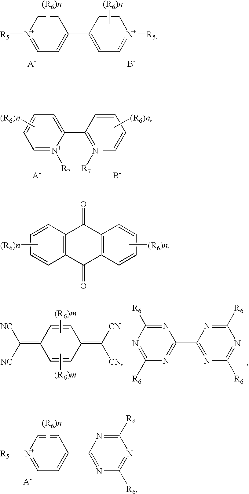
wherein R5 is independently selected from alkyl C1 to C20, alkynyl C2 to C20, and aryl C5 to C20. R5 may optionally contain one or more of an ester, carboxylic acid, metal carboxylate, ether, aryl, amine, urethane, ammonium, thioester, alkene, and alkyne functional group, and additionally may function as a bridge to an energy receptor moiety. R6 is independently selected from hydrogen, alkyl C1 to C10, alkynyl C2 to C10, aryl C5 to C20, and may optionally contain one or more of an ester, carboxylic acid, metal carboxylate, ether, aryl, amine, urethane, ammonium, thioester, alkene, and alkyne functional groups, and additionally may function as a bridge to an energy receptor moiety. R7 is independently selected from alkyl C1 to C5 or an ethyl, propyl or ethylene bridge; n=0-4; m=0-2. Anion A− is a trifluoromethylsulfonate (CF3SO3 −), bis(trifluoromethylsulfonyl)imide ((CF3SO2)2N−), bis(perfluoroethylsulfonyl)imide ((CF3CF2SO2)2N−) or tris(trifluoromethylsulfonyl)methide ((CF3SO2)3C−) anion, and anion B− is a halogen anion, ClO4 −, BF4 −, PF6 −, AsF6 −, SbF6 −, CH3COO−, CH3(C6H4)SO3 −, trifluoromethylsulfonate (CF3SO3 −), bis(trifluoromethylsulfonyl)imide ((CF3SO2)2N−), bis(perfluoroethylsulfonyl)imide ((CF3CF2SO2)2N−) or tris(trifluoromethylsulfonyl)methide ((CF3SO2)3C−) anion. Energy receptor moieties include those having the following chemical structures:

wherein R7 is independently selected from alkyl C1 to C20, alkynyl C2 to C20, and aryl C5 to C20, and may optionally contain one or more of an ester, carboxylic acid, metal carboxylate, ether, aryl, amine, urethane, ammonium, thioester, alkene, and alkyne functional group, and additionally may function as a bridge to the energy receptor moiety. In these formulas, n=0-4 and k=0-5. Any of the above cathodic moieties when suitably bridged to any of the energy receptor moieties forms a bifunctional redox dye, and all of these compounds are examples of bifunctional redox dyes of the invention.

wherein X and Y are independently selected from NH, NR8, S, and O. R8 is independently selected from alkyl C1 to C20, alkynyl C2 to C20, and aryl C5 to C20 and may optionally contain one or more of an ester, carboxylic acid, metal carboxylate, ether, aryl, amine, urethane, ammonium, thioester, alkene, and alkyne functional group, etc, and additionally may function as a bridge to an energy receptor moiety. R9 is independently selected from alkyl C1 to C10, alkyl C2 to C10, aryl C5 to C20, and may optionally contain one or more of an ester, carboxylic acid, metal carboxylate, ether, aryl, amine, urethane, ammonium, thioester, alkene, and alkyne functional group, and additionally may function as a bridge to an energy receptor moiety, and n=0-4, and m=0-2. The energy receptor moiety is one having the structure

or having the structure

wherein R7 is independently selected from alkyl C1 to C20, alkynyl C2 to C20, and aryl C5 to C20 and may optionally contain one or more of an ester, carboxylic acid, metal carboxylate, ether, aryl, amine, urethane, ammonium, thioester, alkene, and alkyne functional group, and additionally may function as a bridge to the energy receptor moiety, n=0-4, and k=0-5. These compounds, which have both an anodic dye moiety and an energy receptor moiety in the same molecule are also examples of bifunctional redox dyes of the invention, and when they are oxidized in ionic liquid solvent, a radical cation is formed that is charge counterbalanced with the anion of the ionic liquid solvent.

which exhibits cathodic electrochromic characteristics, and a metallocene structure represented by formulae

which exhibits anodic electrochromic characteristics. For these compounds, A− is selected from trifluoromethylsulfonate (CF3SO3 −), bis(trifluoromethylsulfonyl)imide ((CF3SO2)2N−), bis(perfluoroethylsulfonyl)imide ((CF3CF2SO2)2N−) and tris(trifluoromethylsulfonyl)methide ((CF3SO2)3C−), and B− is selected from halogen anion, ClO4 −, BF4 −, PF6 −, AsF6 −, SbF6 −, CH3COO−, and CH3(C6H4)SO3 −, trifluoromethylsulfonate (CF3SO3 −), bis(trifluoromethylsulfonyl)imide ((CF3SO2)2N−), bis(perfluoroethylsulfonyl)imide ((CF3CF2SO2)2N−) and tris(trifluoromethylsulfonyl)methide ((CF3SO2)3C−). R10 and R11 are each independently a hydrocarbon group selected from alkyl, alkenyl and aryl groups having 1 to 10 carbon atoms, in the case where R10 or R11 is an aryl group, the aryl group may form a condensed ring together with a cyclopentadienyl ring. Also, m=0-4, n=0-4, and Me represents Cr, Co, Fe, Mn, Ni, Os, Ru, V, Mo(X)(Q), Nb(X)(Q), Ti(X)(Q), V(X)(Q)or Zr(X)(Q) wherein X and Q are each independently selected from hydrogen, halogen, an alkyl group having 1 to 12 carbon atoms, ClO4 −, BF4 −, PF6 −, AsF6 −, SbF6 −, CH3COO−, and CH3(C6H4)SO3 −, trifluoromethylsulfonate (CF3SO3 −), bis(trifluoromethylsulfonyl)imide ((CF3SO2)2N−), bis(perfluoroethylsulfonyl)imide ((CF3CF2SO2)2N−) and tris(trifluoromethylsulfonyl)methide ((CF3SO2)3C−). Examples of the alkyl group are methyl, ethyl, i-propyl, n-propyl, n-butyl, t-butyl, n-pentyl, n-hexyl, and cyclohexyl groups. The aryl group is exemplified by the phenyl group. Particularly preferred are methyl, ethyl, and propyl groups. In the case where R10 or R11 is an aryl group, the aryl group may form a condensed ring by bonding to a cyclopentadienyl ring and R10 or R11 may be a group cross-linking two cyclopentadienyl rings in the metallocene structure. Both m and n are preferably 0 or 1, and particularly preferably 0. Me is preferably Fe.

wherein A− is selected from trifluoromethylsulfonate (CF3SO3 −), bis(trifluoromethylsulfonyl)imide ((CF3SO2)2N−), bis(perfluoroethylsulfonyl)imide ((CF3CF2SO2)2N−) and tris(trifluoromethylsulfonyl)methide ((CF3SO2)3C−), and B− is selected from halogen anion, ClO4 −, BF4 −, PF6 −, AsF6 −, SbF6 −, CH3COO−, and CH3(C6H4)SO3 −, trifluoromethylsulfonate (CF3SO3 −), bis(trifluoromethylsulfonyl)imide ((CF3SO2)2N−), bis(perfluoroethylsulfonyl)imide ((CF3CF2SO2)2N−) and tris(trifluoromethylsulfonyl)methide ((CF3SO2)3C−). R10 and R11 are each independently a hydrocarbon group selected from an alkyl group, alkenyl and aryl group having 1 to 10 carbon atoms, in the case where R10 or R11 is an aryl group, the aryl group may form a condensed ring together with a cyclopentadienyl ring. Also, m=0-4 and n=0-4. R12 and R13 are each independently a hydrocarbon residue having 1 to 20, preferably 1 to 10 carbon atoms, and R14 is a hydrocarbon group selected from the group consisting of an alkyl, cycloalkyl, alkenyl, aryl, or aralkyl group having 1 to 20, preferably 1 to 10 carbon atoms, a heterocyclic group having 4 to 20, preferably 4 to 10 carbon atoms, and a substituted hydrocarbon or heterocyclic group obtained by substituting part of hydrogens of the hydrocarbon group or heterocyclic group with a substituent group. Me represents Cr, Co, Fe, Mn, Ni, Os, Ru, V, Mo(X)(Q), Nb(X)(Q), Ti(X)(Q), V(X)(Q)or Zr(X)(Q) wherein X and Q are each independently selected from hydrogen, halogen, an alkyl group having 1 to 12 carbon atoms, ClO4 −, BF4 −, PF6 −, AsF6 −, SbF6 −, CH3COO−, and CH3(C6H4)SO3 −, trifluoromethylsulfonate (CF3SO3 −), bis(trifluoromethylsulfonyl)imide ((CF3SO2)2N−), bis(perfluoroethylsulfonyl)imide ((CF3CF2SO2)2N−) and tris(trifluoromethylsulfonyl)methide ((CF3SO2)3C−). Examples of the hydrocarbon residue for R12 and R13 are hydrocarbon groups such as alkylene groups and various divalent groups having an ester-bond unit, ether-bond unit, amide-bond unit, thioether-bond unit, amine-bond unit, urethane-bond unit, or silyl unit in the part of hydrocarbon groups. The divalent group having an ester-bond unit may be exemplified by those represented by the formula —R—COO—R— or —R—OCO—R— wherein R is an alkylene group having 1 to 8 carbon atoms. Specific examples of the ester-bond unit are —C4H8—COO—C2H4, —C4H8—OCO—C2H4—, —C4H8—COO—C4H8—, and —C4H8—OCO—C4H8—. The divalent group having an ether-bond unit may be exemplified by those represented by the formula —R—O—R— wherein R is an alkylene group having 1 to 10 carbon atoms. Specific examples of the ether-bond unit are —C4H8—O—C2H4— and —C4H8—O—C4H8—. The divalent group having an amide-bond unit may be exemplified by those represented by the formula —R—CONH—R— or —R—NHCO—R— wherein R is an alkylene group having 1 to 8 carbon atoms. Specific examples of the amide-bond unit are —C4H8—CONH—C2H4—, —C4H8—NHCO—C2H4—, —C4H8—CONH—C4H8—, and —C4H8—NHCO—C4H8—. The divalent group having a thioether-bond unit may be those represented by the formula —R—S—R— wherein R is an alkylene group having 1 to 10 carbon atoms. Specific examples of the thioether-bond unit are —C4H8—S—C2H4— and —C4H8—S—C4H8—. The divalent group having an amine-bond unit may be exemplified by those represented by the formula —R—NH—R— wherein R is an alkylene group having 1 to 10 carbon atoms and the formula —R—NH-Ph- wherein R is an alkylene group having 1 to 10 carbon atoms and Ph is an arylene group or a substituted arylene group having 1 to 12 carbon atoms. Specific examples of the amine-bond unit are —C4H8—NH—C2H4— and —C4H8—NH—C4H8—. The divalent group having a urethane-bond unit may be exemplified by those represented by the formula —R—OCONH—R— or —R—NHCOO—R— wherein R is an alkylene group having 1 to 8 carbon atoms. Specific examples of the urethane-bond unit are —C4H8—OCONH—C2H4—, —C4H8—NHCOO—C4H8—, —C4H8—OCONH—C4H8—, and —C4H8—NHCOO—C4H8—. The divalent groups having a silyl-bond unit may be represented by those represented by the formula —R—Si(R′)2—R— wherein R is an alkylene group having 1 to 8 carbon atoms and R′ is methyl or ethyl. Specific examples of the silyl-bond unit are —C4H8—Si(CH3)2—C2H4—, —C4H8—Si(CH3)2—C4H8—, —C4H8—Si(C2H5)2—C2H4—, and —C4H8—Si(C2H5)2—C4H8—. Examples of the alkyl group for R14 are methyl, ethyl, i-propyl, n-propyl, n-butyl, t-butyl, n-pentyl, n-hexyl, and n-heptyl groups. An example of the cycloalkyl group is cyclohexyl. Examples of the aryl group are phenyl, tolyl, xylyl, and naphthyl. Examples of the alkenyl group are vinyl and allyl groups. Examples of the aralkyl group are benzyl and phenylpropyl groups. Examples of the heterocyclic aromatic group are 2-pyridyl, 4-pyridyl, 2-pyrimidyl, and isoquinoline groups.
Cat1-An1,
or having the formula
Cat1-Bridge1-An1,
or having the formula
Cat1-Bridge1-An1-Bridge2-Cat2,
or having the formula
An2-Bridge2-Cat1-Bridge1-An1,
in which Cat1 and Cat2 independently represent cathodic moieties, and An1 and An2 independently represent anodic moieties. Bridge1 and Bridge2 independently represent a bridge member. These bifunctional redox dyes include at least one anion selected from bis(trifluoromethylsulfonyl)imide ((CF3SO2)2N−), bis(perfluoroethylsulfonyl)imide ((CF3CF2SO2)2N−) and tris(trifluoromethylsulfonyl)methide ((CF3SO2)3C−). The present invention also includes the radical cations of these dyes having these anions. Preferably, Cat1 and Cat2 independently represent the following structural formulae:

in which R17 and R18 independently of one another denote C1 to C18 alkyl, C2 to C12 alkenyl, C3 to C7 cycloalkyl, C7 to C15 aralkyl or C6 to C10 aryl or R17 and R18 together form a —(CH2)2—, —(CH2)3—, or —CH═CH— bridge, R19, R20 and R22 to R25 independently of one another denote hydrogen, C1 to C18 alkyl, C1 to C18 alkoxy, halogen, cyano, nitro or C1 to C18 alkoxycarbonyl or R22 and R23 and/or R24 and R25 form a —CH═CH—CH═CH— bridge. R26, R27, R28 and R29 independently of one another denote hydrogen or, in pairs, a —(CH2)2—, —(CH2)3— or —CH═CH— bridge, E3 and E4 independently of one another denote O, N—CN, C(CN)2 or N—C6 to C10 aryl, R34 and R35 independently denote hydrogen, C1 to C18 alkyl, C1 to C18 alkoxy, halogen, cyano, nitro, C1 to C18 alkoxycarbonyl or C6 to C10 aryl. R30 to R33 independently of one another denote hydrogen or C1 to C6 alkyl, or R30 and R26 and/or R31 and R27 form a —CH═CH—CH═CH— bridge. E1 and E2 independently of one another denote O, S, NR36 or C(R36)2 or E1 and E2 together form a —N—(CH2)2—N— bridge, R36 denotes C1 to C18 alkyl, C2 to C12 alkenyl, C4 to C7 cycloalkyl, C7 to C15 aralkyl or C6 to C10 aryl. Z1 denotes a direct bond, —CH═CH—, —C(CH3)═CH—, —C(CN)═CH—, —CCl═CCl—, —C(OH)═CH—, —CCl═CH—, —C≡C—, —CH═N—N═CH—, —C(CH3)═N—N═C(CH3)— or —CCl═N—N═CCl—. Z2 denotes —(CH2)r— or —CH2—C6H4—CH2—, where r=1-10. C− is selected from bis(trifluoromethylsulfonyl)imide ((CF3SO2)2N−), bis(perfluoroethylsulfonyl)imide ((CF3CF2SO2)2N−) and tris(trifluoromethylsulfonyl)methide ((CF3SO2)3C−), and D− is selected from halogen anion, ClO4 −, BF4 −, PF6 −, AsF6 −, SbF6 −, CH3COO−, CH3(C6H4)SO3 −, trifluoromethylsulfonate (CF3SO3 −), bis(trifluoromethylsulfonyl)imide ((CF3SO2)2N−), bis(perfluoroethylsulfonyl)imide ((CF3CF2SO2)2N−) and tris(trifluoromethylsulfonyl)methide ((CF3SO2)3C−), wherein bonding to the bridge member Bridge1 or Bridge2 is effected via one of the radicals R17-R36, and the radicals mentioned then represent a direct bond.

or An1 or An2 independently represent metal salts that include titanium (III), vanadium (III), vanadium (IV), iron (II), cobalt (II), copper (I), silver (I), indium (I), tin (II), antimony (III), bismuth (III), cerium (III), samarium (II), dysprosium (II), ytterbium (II), or europium (II). R37 to R43 independently of one another denote C1 to C18 alkyl, C2 to C12 alkenyl, C3 to C7 cycloalkyl, C7 to C15 aralkyl or C6 to C10 aryl, and R41 to R43 additionally denote hydrogen, R44 to R50 independently of one another denote hydrogen, C1 to C18 alkyl, C1 to C18 alkoxy, halogen, cyano, nitro, C1 to C18 alkoxycarbonyl or C6 to C10 aryl and R48 and R49 additionally denote an optionally benzo-fused aromatic or quasiaromatic five- or six-membered heterocyclic ring and R50 additionally denotes N(R51))(R52). R44 and R45 and/or R46 and R47 form a —(CH2)3—, —(CH2)4—, —(CH2)5— or —CH═CH—CH═CH— bridge. Z3 denotes a direct bond or a —CH═CH— or —N═N— bridge, =Z4=denotes a direct double bond or a ═CH—CH═ or ═N—N═ bridge. E3 to E4, E10 and E11 independently of one another denote O, S, NR51, C(R51)2, C═O or SO2. E5 to E8 independently of one another denote S, Se or NR51, R5, and R52 independently of one another denote C1 to C12 alkyl, C2 to C8 alkenyl, C3 to C7 cycloalkyl, C7 to C15 aralkyl or C6 to C10 aryl. R53 to R60 independently of one another denote hydrogen, C1 to C6 alkyl, C1 to C4 alkoxy, cyano, C1 to C4 alkoxycarbonyl or C6 to C10 aryl, or R53 and R54 and R59 and R60 independently of one another together form a —(CH2)3—, —(CH2)4— or —CH═CH—CH═CH— bridge, v=0-10, and bonding to the bridge member Bridge1 or Bridge2 is effected by one of the radicals R37-R54, R59, or R60 and the radicals mentioned then represent a direct bond, and Bridge1 or Bridge2 independently represents a bridge member of the formula —(CH2)n— or —(Y1)s—(CH2)m—(Y2)o—(CH2)p—(Y3)q—, each of which is optionally substituted by C1 to C4 alkoxy, halogen or phenyl. Y1 to Y3 independently of one another represents O, S, NR61, COO, CONH, NHCONH, cyclopentanediyl, cyclohexanediyl, phenylene, naphthylene, or beta-dicarbonyl. R61 denotes C1 to C6 alkyl, C2 to C6 alkenyl, C4 to C7 cycloalkyl, C7 to C15 aralkyl or C6 to C10 aryl, n=0-12, m=0-b 8, p=0-12, o=0-6, q=0-1, and s=0-1.
[Cat1][M]
where M is a metal salt that includes a metal such as titanium (III), vanadium (III), vanadium (IV), iron (II), cobalt (II), copper (I), silver (I), indium (I), tin (II), antimony (III), bismuth (III), cerium (III), samarium (II), dysprosium (II), ytterbium (II), or europium (II). An example of this type of bifunctional dye was prepared (see EXAMPLE 11, vide infra).
ln (viscosity)=A+B/(T−Tg)
where T is the temperature of measurement in degrees centigrade, Tg is the glass transition temperature in degrees centigrade, and A and B are the fitting constants for the curve. The value of Tg was determined by varying the assumed value of Tg until the correlation coefficient of the curve was highest. For the fit in
ln (viscosity)=601.41/(T−Tg)−1.1483,
where the curve was best fit by a Tg of −85° C. The best fit equation for the mixture of BMI and propylene carbonate was:
ln (viscosity)=967.35/(T−Tg)−2.694,
where the curve was best fit by a Tg of −130° C.
| TABLE 1 | ||||
| | Device | 1 | |
|
| Ionic Liquid | 18.765 | 20.85 | 0 |
| Propylene carbonate (PC) | 1.7835 | 0 | 17.835 |
| Phenazine | 0.1517 | 0.1517 | 0.1517 |
| Viologen | 0.5809 | 0.5809 | 0.5809 |
| UV Stabilizer | 1.064 | 0.8633 | 0.9284 |
| TABLE 2 | ||||
| |
|
|
||
| % Transmission in bleached | 85 | 85 | 83 |
| state at 550 nm | |||
| % Transmission in colored | 21 | 20 | 31 |
| state at 550 nm | |||
| Leakage current (mA) in | 27.6 | 19.8 | 44.4 |
| fully colored state | |||
| Normalized Leakage | 0.29 | 0.22 | 0.47 |
| current (mA/cm2) | |||


and was used in an EC device. 4-(2-ethylhexyl)-4′-methylenecarboxylate-4,4′-viologen bis(trifluoromethylsulfonyl)imide (602 mg) was mixed with Eu(II) bis(trifluoromethylsulfonyl)imide (518 mg), melted, and maintained as a melt for 15 minutes to form 4-(2-ethylhexyl)-4′-methylenecarboxylate(europium(II))-4,4′-viologen tris(bis(trifluoromethylsulfonyl)imide), which has the structural formula:

An electrochromic device using 4-(2-ethylhexyl)-4′-methylenecarboxylate(europium(II))-4,4′-viologen tris(bis(trifluoromethylsulfonyl)imide) was prepared by dissolving 4-(2-ethylhexyl)-4′-methylenecarboxylate(europium(II))-4,4′-viologen tris(bis(trifluoromethylsulfonyl)imide) (600 mg) in N-butyl-N-methylpyrrolidinium bis(trifluoromethylsulfonyl)imide (BMP, 3 mL). An EC device was prepared by placing the resulting electrolyte solution was placed in the chamber formed by an o-ring and two ITO electrodes. The device successfully colored and bleached repeatedly upon cyclic applications of a voltage to the electrodes of the device, which presumably functions by oxidizing the Eu(II) to Eu(III) and reducing the diethylviologen to the radical cation.
Claims (23)


Cat1-An1,
Cat1-Bridge1-An1,
Cat1-Bridge1-An1-Bridge2-Cat2,
An2-Bridge2-Cat1-Bridge1-An1,


[Cat1][M]


Cat1-An1,
Cat1-Bridge1-An1,
Cat1-Bridge1-An1-Bridge2-Cat2,
An2-Bridge2-Cat1-Bridge1-An1,


[Cat1][M]


Cat1-An1,
Cat1-Bridge1-An1,
Cat1-Bridge1-An1-Bridge2-Cat2,
An2-Bridge2-Cat1-Bridge1-An1,


[Cat1][M]


Priority Applications (6)
| Application Number | Priority Date | Filing Date | Title |
|---|---|---|---|
| US10/600,807 US6853472B2 (en) | 2002-06-21 | 2003-06-20 | Electrolytes for electrooptic devices comprising ionic liquids |
| US10/741,903 US6961168B2 (en) | 2002-06-21 | 2003-12-19 | Durable electrooptic devices comprising ionic liquids |
| US11/041,069 US7119937B2 (en) | 2002-06-21 | 2005-01-20 | Durable electrooptic devices comprising ionic liquids |
| US11/526,416 US7450292B1 (en) | 2003-06-20 | 2006-09-22 | Durable electrooptic devices comprising ionic liquids |
| US11/644,793 US7763186B2 (en) | 2002-06-21 | 2006-12-22 | Preparation and purification of ionic liquids and precursors |
| US12/291,381 US7633669B2 (en) | 2002-06-21 | 2008-11-06 | Durable electrooptic devices comprising ionic liquids |
Applications Claiming Priority (2)
| Application Number | Priority Date | Filing Date | Title |
|---|---|---|---|
| US39061102P | 2002-06-21 | 2002-06-21 | |
| US10/600,807 US6853472B2 (en) | 2002-06-21 | 2003-06-20 | Electrolytes for electrooptic devices comprising ionic liquids |
Related Child Applications (1)
| Application Number | Title | Priority Date | Filing Date |
|---|---|---|---|
| US10/741,903 Continuation-In-Part US6961168B2 (en) | 2002-06-21 | 2003-12-19 | Durable electrooptic devices comprising ionic liquids |
Publications (2)
| Publication Number | Publication Date |
|---|---|
| US20040021928A1 US20040021928A1 (en) | 2004-02-05 |
| US6853472B2 true US6853472B2 (en) | 2005-02-08 |
Family
ID=30000583
Family Applications (1)
| Application Number | Title | Priority Date | Filing Date |
|---|---|---|---|
| US10/600,807 Expired - Lifetime US6853472B2 (en) | 2002-06-21 | 2003-06-20 | Electrolytes for electrooptic devices comprising ionic liquids |
Country Status (7)
| Country | Link |
|---|---|
| US (1) | US6853472B2 (en) |
| EP (1) | EP1529240A4 (en) |
| JP (2) | JP4214112B2 (en) |
| CN (2) | CN101293900A (en) |
| AU (1) | AU2003256281A1 (en) |
| BR (1) | BR0305630A (en) |
| WO (1) | WO2004001877A2 (en) |
Cited By (47)
| Publication number | Priority date | Publication date | Assignee | Title |
|---|---|---|---|---|
| US20050002080A1 (en) * | 2003-06-18 | 2005-01-06 | Kabushiki Kaisha Tokai-Rika-Denki-Seisakusho | Electrochromic mirror having variable reflectivity |
| US20050243597A1 (en) * | 2004-04-29 | 2005-11-03 | Zettacore, Inc. | Systems, tools and methods for production of molecular memory |
| US20050270820A1 (en) * | 2004-01-28 | 2005-12-08 | Mobley Kenneth J | Molecular memory |
| US20060092687A1 (en) * | 2004-01-28 | 2006-05-04 | Zettacore, Inc. | Molecular memory devices and methods |
| US20060137502A1 (en) * | 1999-02-05 | 2006-06-29 | Hitachi Koki Co., Ltd. | Cutter with laser generator that irradiates cutting position on workpiece to faciliate alignment of blade with cutting position |
| US20060285190A1 (en) * | 2005-06-17 | 2006-12-21 | Electrochromix, Inc. | Environmentally safe electrochromic mirrors |
| US20070047095A1 (en) * | 2005-08-23 | 2007-03-01 | Samsung Electro-Mechanics Co., Ltd. | Electrowetting system with stable movement |
| US20070092801A1 (en) * | 2005-10-25 | 2007-04-26 | Andrew Tipton | Molten Salt Electrolyte for a Battery and Electrochemical Capacitor |
| US20070097598A1 (en) * | 2002-10-31 | 2007-05-03 | Honeywell International Inc. | Direct process for the manufacture of tetraalkylammonium tetrafluoroborate-containing electrolyte compositions |
| US20070129568A1 (en) * | 2005-12-06 | 2007-06-07 | Ngimat, Co. | Ionic liquids |
| WO2007104144A1 (en) * | 2006-03-10 | 2007-09-20 | Transfert Plus, S.E.C. | Compounds, ionic liquids, molten salts and uses thereof |
| US20070285759A1 (en) * | 2006-06-09 | 2007-12-13 | Ash Kevin L | Variable Transmission Window System |
| US20080007086A1 (en) * | 2005-12-10 | 2008-01-10 | Ram Pattikonda | Vehicle shading system and method using an electrically controlled transmission control material |
| US20080214814A1 (en) * | 2006-07-18 | 2008-09-04 | Zaiwei Li | Stable ionic liquid complexes and methods for determining stability thereof |
| US20080219041A1 (en) * | 2004-01-28 | 2008-09-11 | Kuhr Werner G | Processing Systems and Methods for Molecular Memory |
| US20090029263A1 (en) * | 2004-10-12 | 2009-01-29 | Hydro-Quebec | Aprotic polymer/molten salt ternary mixture solvent, method for the production and use thereof in electrochemical systems |
| US7642546B2 (en) | 2005-12-01 | 2010-01-05 | Zettacore, Inc. | Molecular memory devices including solid-state dielectric layers and related methods |
| US20100039690A1 (en) * | 2008-05-19 | 2010-02-18 | Ajjer Llc | Composite electrode and electrolytes comprising nanoparticles and resulting devices |
| US20100067090A1 (en) * | 2008-09-17 | 2010-03-18 | Peter Egerton | Electrical Contact Technique For Electrochromic Windows |
| US20110051219A1 (en) * | 2008-01-31 | 2011-03-03 | Electrochromix Inc. | Environmentally safe electrochromic devices and assemblies |
| US20110157774A1 (en) * | 2008-09-09 | 2011-06-30 | Phillip Brett Aitchison | Package for an Electrical Device |
| US20110211246A1 (en) * | 2008-01-31 | 2011-09-01 | Ajjer Llc | Conductive busbars and sealants for chromogenic devices |
| US8643933B2 (en) | 2011-12-14 | 2014-02-04 | View, Inc. | Connectors for smart windows |
| US8711465B2 (en) | 2010-12-08 | 2014-04-29 | View, Inc. | Spacers for insulated glass units |
| US20140249606A1 (en) * | 2011-05-12 | 2014-09-04 | Merck Patent Gmbh Patents & Scientific Information | Organic ionic compounds, compositions and electronic devices |
| US8936882B2 (en) | 2011-08-29 | 2015-01-20 | Uchicago Argonne, Llc | Electrolyte compositions for lithium and lithium-ion batteries |
| US9252459B2 (en) | 2011-12-23 | 2016-02-02 | Semiconductor Energy Co., Ltd. | Ionic liquid, nonaqueous electrolyte, and power storage device |
| US9341909B2 (en) | 2008-06-25 | 2016-05-17 | View, Inc. | Multi-pane dynamic window and method for making same |
| US9341912B2 (en) | 2012-03-13 | 2016-05-17 | View, Inc. | Multi-zone EC windows |
| US9405165B2 (en) | 2012-03-30 | 2016-08-02 | Gentex Corporation | Controller configured for an electro-optic device and method thereof |
| US9442339B2 (en) | 2010-12-08 | 2016-09-13 | View, Inc. | Spacers and connectors for insulated glass units |
| US9482922B2 (en) | 2011-03-16 | 2016-11-01 | View, Inc. | Multipurpose controller for multistate windows |
| US9703167B2 (en) | 2010-11-08 | 2017-07-11 | View, Inc. | Electrochromic window fabrication methods |
| US10137764B2 (en) | 2016-05-20 | 2018-11-27 | Gentex Corporation | Electro-optic window control system |
| US10167073B2 (en) | 2015-06-09 | 2019-01-01 | Gentex Corporation | Multi-piece bezel for electro-optic window assembly |
| US10288971B2 (en) | 2012-08-23 | 2019-05-14 | View, Inc. | Photonic-powered EC devices |
| US10294415B2 (en) | 2014-06-09 | 2019-05-21 | iGlass Technology, Inc. | Electrochromic composition and electrochromic device using same |
| US10344208B2 (en) | 2014-06-09 | 2019-07-09 | iGlass Technology, Inc. | Electrochromic device and method for manufacturing electrochromic device |
| US10359682B2 (en) | 2013-10-04 | 2019-07-23 | Gentex Corporation | Variable transmittance window system |
| US10429712B2 (en) | 2012-04-20 | 2019-10-01 | View, Inc. | Angled bus bar |
| US10481458B2 (en) | 2013-06-18 | 2019-11-19 | View, Inc. | Electrochromic devices on non-rectangular shapes |
| US10589834B2 (en) | 2015-06-09 | 2020-03-17 | Gentex Corporation | Retention of an electro-optic window assembly |
| US10665899B2 (en) | 2017-07-17 | 2020-05-26 | NOHMs Technologies, Inc. | Phosphorus containing electrolytes |
| US10868332B2 (en) | 2016-04-01 | 2020-12-15 | NOHMs Technologies, Inc. | Modified ionic liquids containing phosphorus |
| US11287717B2 (en) | 2020-04-09 | 2022-03-29 | Glass Dyenamics | Variable light transmission structures with improved optical properties |
| US11635666B2 (en) | 2012-03-13 | 2023-04-25 | View, Inc | Methods of controlling multi-zone tintable windows |
| US11649670B2 (en) | 2020-04-09 | 2023-05-16 | Glass Dyenamics | Insulated glass units with variable light transmission structures |
Families Citing this family (43)
| Publication number | Priority date | Publication date | Assignee | Title |
|---|---|---|---|---|
| US6961168B2 (en) * | 2002-06-21 | 2005-11-01 | The Regents Of The University Of California | Durable electrooptic devices comprising ionic liquids |
| US7763186B2 (en) * | 2002-06-21 | 2010-07-27 | Los Alamos National Security, Llc | Preparation and purification of ionic liquids and precursors |
| EP1608719A2 (en) * | 2003-03-05 | 2005-12-28 | Electrochromix, Inc | Electrochromic mirrors and other electrooptic devices |
| US20050200934A1 (en) * | 2004-03-12 | 2005-09-15 | The Boeing Company | Dimming control system for an array of electrochromic devices |
| US8064120B2 (en) * | 2004-03-12 | 2011-11-22 | The Boeing Company | Aircraft cabin services system including zone controllers for lighting control modules and dimmable windows |
| US7450294B2 (en) * | 2004-03-12 | 2008-11-11 | Boeing Co | Multi-color electrochromic apparatus and methods |
| CN1934212B (en) * | 2004-04-19 | 2010-12-22 | Lg化学株式会社 | Gel polymer electrolyte containing ionic liquid and electrochromic device using the same |
| FR2872349B1 (en) * | 2004-06-28 | 2006-10-06 | Batscap Sa | IONIC CONDUCTION MATERIAL CONTAINING AN OLIGOETHER SULFATE |
| JP4546266B2 (en) * | 2005-01-13 | 2010-09-15 | シャープ株式会社 | Sheet image display device |
| JP4669754B2 (en) * | 2005-03-09 | 2011-04-13 | 富士フイルム株式会社 | Dye composition and dyeing method |
| US7355161B2 (en) * | 2005-12-15 | 2008-04-08 | The Boeing Company | Systems and methods for controlling windows with variable light transmission |
| JP4816069B2 (en) * | 2005-12-26 | 2011-11-16 | ソニー株式会社 | Electrochromic device |
| CN101379099B (en) | 2006-02-07 | 2011-01-12 | 大金工业株式会社 | Fluorine-containing polymer containing heteroaromatic ring |
| US7893890B2 (en) * | 2007-03-05 | 2011-02-22 | The Boeing Company | Electrically dimmable combiner optics for head-up display |
| EP1988514A1 (en) | 2007-05-04 | 2008-11-05 | Acreo AB | Security document circuit |
| CN101468969B (en) * | 2007-12-28 | 2010-10-13 | 中国科学院兰州化学物理研究所 | Photoresponse ion liquid and preparation thereof |
| FR2928375B1 (en) * | 2008-03-05 | 2010-04-30 | Essilor Int | COMPOSITION OF PHOTOCHROMIC DYES IN ION SOLVENT. |
| CN101436467B (en) * | 2008-12-15 | 2012-05-16 | 中国科学院长春应用化学研究所 | Ion liquid electrolyte containing bi-(fluorosulfonic acid) imines ion and iodine ion, and application thereof |
| CN101587956B (en) * | 2009-06-15 | 2011-05-25 | 浙江工业大学 | Ternary perfluor organic molten salt electrolyte, preparation method and application thereof |
| JP5530692B2 (en) * | 2009-09-30 | 2014-06-25 | 太陽ホールディングス株式会社 | Electrochromic composition |
| JP5564289B2 (en) * | 2010-03-02 | 2014-07-30 | 太陽ホールディングス株式会社 | Electrochromic composition |
| TW201215980A (en) * | 2010-10-05 | 2012-04-16 | J Touch Corp | Electrochromic module and stereoscopic image display device having the same |
| CN102540613A (en) * | 2010-12-28 | 2012-07-04 | 京东方科技集团股份有限公司 | Method and apparatus for manufacturing electrophoretic display device |
| DE102011003197A1 (en) * | 2011-01-26 | 2012-07-26 | Robert Bosch Gmbh | Redox additive for secondary cells with liquid-solid phase change |
| TWI450009B (en) * | 2011-05-30 | 2014-08-21 | Asiatree Technology Co Ltd | Electrochromic device and method of manufacturing the same |
| JP5796128B2 (en) * | 2011-08-30 | 2015-10-21 | オーシャンズ キング ライティング サイエンスアンドテクノロジー カンパニー リミテッド | Bipyridyl cationic ionic liquid having two centers, its preparation method and use |
| US10681928B2 (en) * | 2012-02-17 | 2020-06-16 | Conagra Foods Rdm, Inc. | Food product and coating |
| WO2013142994A1 (en) * | 2012-03-30 | 2013-10-03 | Valorisation-Recherche, Limited Partnership | Redox-active ionic liquids |
| CN103426637A (en) * | 2012-05-14 | 2013-12-04 | 海洋王照明科技股份有限公司 | Capacitor electrolyte solution and preparing method thereof |
| US9318271B2 (en) * | 2012-06-21 | 2016-04-19 | Schlumberger Technology Corporation | High temperature supercapacitor |
| CN103936677B (en) * | 2013-01-21 | 2016-06-29 | 中国科学院大连化学物理研究所 | A kind of sulfonic acid funtionalized ionic liquid based on perfluoro alkyl sulfonic acid root anion and preparation method thereof |
| CN103094616A (en) * | 2013-01-30 | 2013-05-08 | 江西优锂新材股份有限公司 | Electrolyte additive, high-voltage electrolyte and lithium ion battery containing electrolyte additive |
| WO2015016764A1 (en) * | 2013-07-29 | 2015-02-05 | Chromogenics Ab | Contacting of electrochromic devices |
| CN104122310A (en) * | 2014-08-06 | 2014-10-29 | 中国电子科技集团公司第四十九研究所 | Water-soluble electrolyte system and application of water-soluble electrolyte system in electrochemical oxygen sensor |
| CN104496928A (en) * | 2014-11-21 | 2015-04-08 | 绍兴佳华高分子材料股份有限公司 | Method for preparing quaternary ammonium salt ionic liquid without halogen ions and sodium ions |
| EP3338140A1 (en) * | 2015-08-21 | 2018-06-27 | Essilor International | Active optical filter for spectacle lenses |
| JP6439645B2 (en) * | 2015-10-08 | 2018-12-19 | 株式会社村田製作所 | Batteries, battery packs, electronic devices, electric vehicles, power storage devices, and power systems |
| US10678068B2 (en) * | 2015-12-18 | 2020-06-09 | Verily Life Sciences Llc | Electrochromic contact lens |
| WO2017191481A1 (en) * | 2016-05-06 | 2017-11-09 | Centre National De La Recherche Scientifique (Cnrs) | Electroactive ionic liquids and surface-modified substrates containing them |
| US20190103627A1 (en) * | 2017-10-04 | 2019-04-04 | Wildcat Discovery Technologies, Inc. | Solid electrolyte compositions |
| CN108490713A (en) * | 2018-02-26 | 2018-09-04 | 江苏天贯碳纳米材料有限公司 | A kind of electrochromic device and its use the filling preparation method of hole |
| CN110416614B (en) * | 2019-08-02 | 2022-08-26 | 湖州昆仑亿恩科电池材料有限公司 | Electrolyte for high-nickel lithium ion battery |
| US20220219254A1 (en) * | 2021-01-13 | 2022-07-14 | Carlex Glass America, Llc | Method of connection to a conductive material |
Citations (32)
| Publication number | Priority date | Publication date | Assignee | Title |
|---|---|---|---|---|
| US3451741A (en) * | 1966-06-15 | 1969-06-24 | Du Pont | Electrochromic device |
| US3453038A (en) * | 1966-06-15 | 1969-07-01 | Du Pont | Compartmented electrochromic device |
| US3637611A (en) * | 1969-03-26 | 1972-01-25 | Sumitomo Chemical Co | Novel alternating copolymer of multisubstituted conjugated vinyl compound and unsaturated compound and process for producing same |
| US3651019A (en) * | 1961-09-28 | 1972-03-21 | Yeda Res & Dev | Production of adducts of carbon tetrachloride or chloroform with olefinically unsaturated substances |
| US4671619A (en) | 1984-07-24 | 1987-06-09 | Asahi Glass Company, Ltd. | Electro-optic device |
| US4902108A (en) | 1986-03-31 | 1990-02-20 | Gentex Corporation | Single-compartment, self-erasing, solution-phase electrochromic devices, solutions for use therein, and uses thereof |
| US5140455A (en) | 1989-11-29 | 1992-08-18 | Donnelly Corporation | High performance electrochemichromic solutions and devices thereof |
| US5729379A (en) | 1994-10-26 | 1998-03-17 | Donnelly Corporation | Electrochromic devices |
| US5827602A (en) | 1995-06-30 | 1998-10-27 | Covalent Associates Incorporated | Hydrophobic ionic liquids |
| JPH10329479A (en) | 1997-05-30 | 1998-12-15 | Pentel Kk | Coating applicator |
| US5864419A (en) | 1988-02-12 | 1999-01-26 | Donnelly Corporation | Near-infrared reflecting, ultraviolet protected, safety protected, electrochromic vehicular glazing |
| US5940201A (en) | 1997-04-02 | 1999-08-17 | Gentex Corporation | Electrochromic mirror with two thin glass elements and a gelled electrochromic medium |
| US5998617A (en) | 1997-04-02 | 1999-12-07 | Gentex Corporation | Electrochromic compounds |
| US6141137A (en) | 1998-08-26 | 2000-10-31 | Gentex Corporation | Electrochromic media for producing a preselected color |
| US6172794B1 (en) | 1996-02-23 | 2001-01-09 | Pilkington Plc | Electrochromic devices |
| US6178034B1 (en) | 1996-04-10 | 2001-01-23 | Donnelly Corporation | Electrochromic devices |
| US6241916B1 (en) | 1996-02-15 | 2001-06-05 | Bayer Aktiengesellschaft | Electrochromic system |
| US6245262B1 (en) | 1993-02-26 | 2001-06-12 | Donnelly Corporation | Electrochromic polymeric solid films, manufacturing electrochromic devices using such solid films, and processes for making such films and devices |
| US6246505B1 (en) | 1995-02-10 | 2001-06-12 | Donnelly Corporation | Photochromic devices |
| JP2001193363A (en) | 2000-01-05 | 2001-07-17 | Kawamura Electric Inc | Glass fall preventive fitting of resin made window frame |
| US6266177B1 (en) | 1999-11-18 | 2001-07-24 | Donnelly Corporation | Electrochromic devices |
| WO2001063350A1 (en) | 2000-02-24 | 2001-08-30 | Gentex Corporation | Substituted metallocenes for use as anodic electrochromic materials, and electrochromic media and devices comprising the same |
| US6310714B1 (en) | 1999-08-19 | 2001-10-30 | Gentex Corporation | Color-stabilized electrochromic devices |
| US6317248B1 (en) | 1998-07-02 | 2001-11-13 | Donnelly Corporation | Busbars for electrically powered cells |
| US6319428B1 (en) * | 1996-12-30 | 2001-11-20 | Hydro-Quebec | Perfluorinated amide salts and their uses as ionic conducting materials |
| US6327070B1 (en) | 1998-05-29 | 2001-12-04 | Bayer Aktiengesellschaft | Electrochromic assembly based on poly(3,4-ethylenedioxythiophene) derivatives in combination with a lithium niobate counterelectrode |
| US20020012155A1 (en) | 1999-08-02 | 2002-01-31 | Baumann Kelvin L. | Electrochromic materials with enhanced ultraviolet stability and devices comprising same |
| US6344918B1 (en) | 1999-03-29 | 2002-02-05 | Bayer Aktiengesellschaft | Electrochromic contrast-plate |
| US6365301B1 (en) | 1998-02-03 | 2002-04-02 | Acep, Inc. | Materials useful as electrolytic solutes |
| US6372159B1 (en) | 1997-08-18 | 2002-04-16 | Bayer Aktiengesellschaft | UV-protected electrochromic solution |
| US6519072B2 (en) | 1999-02-18 | 2003-02-11 | Nippon Mitsubishi Oil Corporation | Electrochromic device |
| US20030030883A1 (en) | 1999-12-03 | 2003-02-13 | Punam Giri | Ultraviolet stabilizing materials having a solublizing moiety |
Family Cites Families (12)
| Publication number | Priority date | Publication date | Assignee | Title |
|---|---|---|---|---|
| CN1147954C (en) * | 1995-11-15 | 2004-04-28 | 旭化成电子材料元件株式会社 | Composite polymer solid electrolyte and nonaqueous electrochemical device |
| JPH10168028A (en) | 1996-12-10 | 1998-06-23 | Mitsubishi Chem Corp | Normal temperature-melting salt and electrochemical device using the same |
| JPH11106440A (en) * | 1997-10-03 | 1999-04-20 | Sansui Kk | Copolymer for solidifying electrolyte solution, electrolyte solution-solidifying agent and solid electrolyte |
| JP2000131722A (en) * | 1998-10-22 | 2000-05-12 | Nippon Mitsubishi Oil Corp | Electrochromic element |
| EP1010741B1 (en) * | 1998-12-14 | 2003-10-15 | Nippon Mitsubishi Oil Corporation | Electrochromic device |
| US6262832B1 (en) * | 1999-12-03 | 2001-07-17 | Gentex Corporation | Anodic electrochromic materials having a solublizing moiety |
| DE60028711T2 (en) * | 1999-12-23 | 2007-05-24 | Rohm And Haas Co. | Additives for plastics, manufacturing and blends |
| JP2001209078A (en) * | 2000-01-26 | 2001-08-03 | Nippon Mitsubishi Oil Corp | Electrochromic device |
| DE10023765A1 (en) * | 2000-05-15 | 2001-11-22 | Bayer Ag | Electrochromic device, useful as a window, separating screen, protective screen, glazing, roof glazing, light filter, mirror or display device contains a bridged bipyridinium salt compound |
| US20020110739A1 (en) | 2000-05-26 | 2002-08-15 | Mcewen Alan B. | Non-flammable electrolytes |
| JP4360663B2 (en) * | 2000-09-01 | 2009-11-11 | 新日本石油株式会社 | Electrochromic mirror |
| JP4166505B2 (en) * | 2002-05-24 | 2008-10-15 | 新日本石油株式会社 | Polymer solid electrolyte |
-
2003
- 2003-06-20 JP JP2004516104A patent/JP4214112B2/en not_active Expired - Fee Related
- 2003-06-20 BR BR0305630-9A patent/BR0305630A/en not_active IP Right Cessation
- 2003-06-20 AU AU2003256281A patent/AU2003256281A1/en not_active Abandoned
- 2003-06-20 CN CNA2008100834120A patent/CN101293900A/en active Pending
- 2003-06-20 WO PCT/US2003/019677 patent/WO2004001877A2/en active Application Filing
- 2003-06-20 EP EP03761234A patent/EP1529240A4/en not_active Withdrawn
- 2003-06-20 US US10/600,807 patent/US6853472B2/en not_active Expired - Lifetime
- 2003-06-20 CN CNB038173840A patent/CN100386691C/en not_active Expired - Fee Related
-
2008
- 2008-09-10 JP JP2008232311A patent/JP2009053700A/en active Pending
Patent Citations (37)
| Publication number | Priority date | Publication date | Assignee | Title |
|---|---|---|---|---|
| US3651019A (en) * | 1961-09-28 | 1972-03-21 | Yeda Res & Dev | Production of adducts of carbon tetrachloride or chloroform with olefinically unsaturated substances |
| US3451741A (en) * | 1966-06-15 | 1969-06-24 | Du Pont | Electrochromic device |
| US3453038A (en) * | 1966-06-15 | 1969-07-01 | Du Pont | Compartmented electrochromic device |
| US3637611A (en) * | 1969-03-26 | 1972-01-25 | Sumitomo Chemical Co | Novel alternating copolymer of multisubstituted conjugated vinyl compound and unsaturated compound and process for producing same |
| US4671619A (en) | 1984-07-24 | 1987-06-09 | Asahi Glass Company, Ltd. | Electro-optic device |
| US4902108A (en) | 1986-03-31 | 1990-02-20 | Gentex Corporation | Single-compartment, self-erasing, solution-phase electrochromic devices, solutions for use therein, and uses thereof |
| US5864419A (en) | 1988-02-12 | 1999-01-26 | Donnelly Corporation | Near-infrared reflecting, ultraviolet protected, safety protected, electrochromic vehicular glazing |
| US6122093A (en) | 1988-02-12 | 2000-09-19 | Donnelly Corporation | Reduced ultraviolet radiation transmitting, safety protected electrochromic glazing assembly |
| US5140455A (en) | 1989-11-29 | 1992-08-18 | Donnelly Corporation | High performance electrochemichromic solutions and devices thereof |
| US6045724A (en) | 1989-11-29 | 2000-04-04 | Donnelly Corporation | Large area electrochromic window |
| US6245262B1 (en) | 1993-02-26 | 2001-06-12 | Donnelly Corporation | Electrochromic polymeric solid films, manufacturing electrochromic devices using such solid films, and processes for making such films and devices |
| US5729379A (en) | 1994-10-26 | 1998-03-17 | Donnelly Corporation | Electrochromic devices |
| US6246505B1 (en) | 1995-02-10 | 2001-06-12 | Donnelly Corporation | Photochromic devices |
| US5827602A (en) | 1995-06-30 | 1998-10-27 | Covalent Associates Incorporated | Hydrophobic ionic liquids |
| US6241916B1 (en) | 1996-02-15 | 2001-06-05 | Bayer Aktiengesellschaft | Electrochromic system |
| US6172794B1 (en) | 1996-02-23 | 2001-01-09 | Pilkington Plc | Electrochromic devices |
| US6178034B1 (en) | 1996-04-10 | 2001-01-23 | Donnelly Corporation | Electrochromic devices |
| US6319428B1 (en) * | 1996-12-30 | 2001-11-20 | Hydro-Quebec | Perfluorinated amide salts and their uses as ionic conducting materials |
| US6365068B1 (en) * | 1996-12-30 | 2002-04-02 | Hydro-Quebec | Heterocyclic aromatic anion salts, and their uses as ionic conducting materials |
| US6420036B1 (en) | 1997-03-26 | 2002-07-16 | Donnelly Corporation | Electrochromic polymeric solid films, manufacturing electrochromic devices using such solid films, and processes for making such solid films and devices |
| US5998617A (en) | 1997-04-02 | 1999-12-07 | Gentex Corporation | Electrochromic compounds |
| US5940201A (en) | 1997-04-02 | 1999-08-17 | Gentex Corporation | Electrochromic mirror with two thin glass elements and a gelled electrochromic medium |
| JPH10329479A (en) | 1997-05-30 | 1998-12-15 | Pentel Kk | Coating applicator |
| US6372159B1 (en) | 1997-08-18 | 2002-04-16 | Bayer Aktiengesellschaft | UV-protected electrochromic solution |
| US6365301B1 (en) | 1998-02-03 | 2002-04-02 | Acep, Inc. | Materials useful as electrolytic solutes |
| US6327070B1 (en) | 1998-05-29 | 2001-12-04 | Bayer Aktiengesellschaft | Electrochromic assembly based on poly(3,4-ethylenedioxythiophene) derivatives in combination with a lithium niobate counterelectrode |
| US6317248B1 (en) | 1998-07-02 | 2001-11-13 | Donnelly Corporation | Busbars for electrically powered cells |
| US6141137A (en) | 1998-08-26 | 2000-10-31 | Gentex Corporation | Electrochromic media for producing a preselected color |
| US6519072B2 (en) | 1999-02-18 | 2003-02-11 | Nippon Mitsubishi Oil Corporation | Electrochromic device |
| US6344918B1 (en) | 1999-03-29 | 2002-02-05 | Bayer Aktiengesellschaft | Electrochromic contrast-plate |
| US20020012155A1 (en) | 1999-08-02 | 2002-01-31 | Baumann Kelvin L. | Electrochromic materials with enhanced ultraviolet stability and devices comprising same |
| US6362914B2 (en) | 1999-08-02 | 2002-03-26 | Gentex Corporation | Electrochromic materials with enhanced ultraviolet stability and devices comprising same |
| US6310714B1 (en) | 1999-08-19 | 2001-10-30 | Gentex Corporation | Color-stabilized electrochromic devices |
| US6266177B1 (en) | 1999-11-18 | 2001-07-24 | Donnelly Corporation | Electrochromic devices |
| US20030030883A1 (en) | 1999-12-03 | 2003-02-13 | Punam Giri | Ultraviolet stabilizing materials having a solublizing moiety |
| JP2001193363A (en) | 2000-01-05 | 2001-07-17 | Kawamura Electric Inc | Glass fall preventive fitting of resin made window frame |
| WO2001063350A1 (en) | 2000-02-24 | 2001-08-30 | Gentex Corporation | Substituted metallocenes for use as anodic electrochromic materials, and electrochromic media and devices comprising the same |
Non-Patent Citations (44)
| Title |
|---|
| "Ultraviolet Stabilizers," Modern Plastics World Encyclopedia, pp. C-120-C-123, 2001. |
| A. W. Czanderna, D. K. Benson, G. J. Jorgensen, J.-G. Zhang, C. E. Tracy, and S. K. Deb, "Durability Issues and Service Lifetime Prediction of Electrochromic Windows for Buildings Applications," Solar Energy Materials & Solar Cells, vol. 56, pp. 419-436, 1999. |
| Alan B. McEwen et al., "Non-Flammable Electrolytes," WO 01/93363, published Dec. 6, 2001. |
| Anoop Agrawal et al., "Busbars for Electrically Powered Cells," U.S. Appl. No. 6,317,248, issued Nov. 13, 2001. |
| Charles M. Gordon, "New Developments in Catalysis Using Ionic Liquids," Applied Catalysis A: General, vol. 222, pp. 101-117, 2001. |
| Christophe Michot et al., "Materials Useful as Electrolytic Solutes," U.S. Appl. Ser. No. 6,365,301 issued Apr. 2, 2002. |
| Clemens Bechinger, Suzanne Ferrere, Arie Zaban, Julian Sprague, and Brian A. Greeg,"Photoelectrochromic Windows and Displays," Nature, vol. 383, pp. 608-610, Oct. 1996. |
| D. Behar, P. Neta, and Carl Schultheisz, "Reaction Kinetics in Ionic Liquids as Studied by Pulse Radiolysis: Redox Reactions in the Solvents Methyltributylammonium Bis(trifluoromethylsulfonyl)imide and N-Butylpyridinium Tetrafluoroborate," J. Phys. Chem. A, vol. 106, pp. 3139-3147, 2002. |
| Dave Thieste et al., "Near Infrared-Absorbing Electrochromic Compounds and Devices Comprising the Same," WO 99/45081, published Sep. 10, 1999. |
| Dave Thieste, Harlan J. Byker, Kelvin Baumann, and Ramanujan Srinivasa, "Near Infrared-Absorbing Electrochromic Compounds and Devices Comprising the Same," PCT Application WO 99/45081, published Sep. 10, 1999. |
| Desaraju V. Varaprasad et al., "Electrochromic Polymeric Solid Films, Manufacturing Electrochromic Devices Using Such Solid Films, and Processes for Making Such Films and Devices," U.S. Pat. No. 6,245,262, issued Jun. 12, 2001. |
| Desaraju V. Varaprasad et al., "High Performance Electrochemichromic Solutions and Devices Thereof," U.S. Pat. No. 5,140,455, issued Aug. 18, 1992. |
| Desaraju V. Varaprasad et al., "Large Area Electrochromic Window," U.S. Pat. No. 6,045,724, issued Apr. 4, 2000. |
| Desarju V. Varaprasad et al., "Electrochromic Polymeric Solid Films, Manufacturing Electrochromic Devices Using Such Solid Films, and Processes for Making Such Solid Films and Devices," U.S. Appl. No. 6,420,036, issued Jul. 16, 2002. |
| Gimtong Teowee et al., "Photochromic Devices," U.S. Pat. No. 6,246,505, issued Jun. 12, 2001. |
| Harlan J. Byker et al., "Electrochromic Media for Producing a Preselected Color," U.S. Pat. No. 6,141,137, issued Oct. 31, 2000. |
| Harlan J. Byker, "Single-Compartment, Self-Erasing, Solution-Phase Electrochromic Devices, Solutions for Use Therein and Uses Thereof," U.S. Pat. No. 4,902,108, issued Feb. 20, 1990. |
| Helmut-Werner Heuer et al., "Electrochromic Assembly Based on Poly(3,4-ethylenedioxythiophene) Derivatives in Combination With a Lithium Niobate Counterelectrode," U.S. Pat. No. 6,327,070, issued Dec. 4, 2001. |
| Horst Berneth et al., "Electrochromic Contrast-Plate," U.S. Pat. No. 6,344,918, issued Feb. 5, 2002. |
| Horst Berneth et al., "UV-Protected Electrochromic Solution," U.S. Pat. No. 6,372,159, issued Apr. 16, 2002. |
| J. Sun, M. Forsyth, and D. R. MacFarlane, "Room-Temperature Molten Salts Based on the Quaternary Ammonium Ion," J. Phys. Chem. B. vol. 102, pp. 8858-8865, 1998. |
| Jeffrey R. Lomprey et al., "Color-Stabilized Electrochromic Devices," U.S. Pat. No. 6,310,714, issued Oct. 30, 2001. |
| Jeffrey R. Lomprey, "Substituted Metallocenes for Use as Anodic Electrochromic Materials, and Electrochromic Media and Devices Comprising the Same," WO 01/63350, published Aug. 30, 2001. |
| Kelvin L. Baumann et al., "Electrochromic Materials with Enhanced Ultraviolet Stability and Devices Comprising Same," U. S. Patent Publication 2002/0012155, issued Jan. 31, 2002. |
| Kelvin L. Baumann et al., "Electrochromic Materials with Enhanced Ultraviolet Stability and Devices Comprising Same," U.S. Pat. No. 6,362,914, issued Mar. 26, 2002. |
| Kevin L. Ash et al., "Electrochromic Mirror with Two Thin Glass Elements and a Gelled Electrochromic Medium," U.S. Appl. No. 5,940,201, issued Aug. 17, 1999. |
| Kirk-Othmer Encyclopedia of Chemical Technology, 4<th >edition, vol. 3, pp. 1016-1018, pp. 1107-1109; and vol. 15, pp. 446-447. |
| Mark J. Muldoon, Andrew J. McClean, Charles M. Gordon, and Ian R. Dunkin, "Hydrogen Abstraction From Ionic Liquids by Benzophenone Triplet Excited States," Chem. Commun., pp. 2364-2365, 2001. |
| Mark Niemeyer, "sigma-Donor Versus eta<6>pi-Arene Interactions in Monomeric Europium(II) and Ytterbium(II) Thiolates-An Experimental and Computational Study," Eur. J. Inorg. Chem., pp. 1969-1981, 2001. |
| Mark Samuel Burdis, "Electrochromic Devices," U.S. Pat. No. 6,172,794, issued Jan. 9, 2001. |
| Martyn J. Earle, Paul B. McCormac, and Kenneth R. Seddon, "Diels-Alder Reactions in Ionic Liquids," Green Chemistry, pp. 23-25, Feb. 1999. |
| Niall R. Lynam, "Near-Infrared Reflecting, Safety Protected, Electrochromic Vehicular Glazing," U.S. Appl. No. 5,864,419, issued Jan. 26, 1999. |
| Niall R. Lynam, "Reduced Ultraviolet Radiation Transmitting, Safety Protected Electrochromic Glazing Assembly," U.S. Appl. No. 6,122,093, issued Sep. 19, 2000. |
| Pierre-Marc Allemand et al., "Electrochromic Devices," U.S. Pat. No. 5,729,379, issued Mar. 17, 1998. |
| Pierre-Marc Allemand et al., "Electrochromic Devices," U.S. Pat. No. 6,178,034, issued Jan. 23, 2001. |
| Pierre-Marc Allemand et al., "Electrochromic Devices," U.S. Pat. No. 6,266,177, issued Jul. 24, 2001. |
| Punam Giri, Leroy J. Kloeppner, K. L. Baumann, J. R. Lomprey, and Thomas F. Guarr, "Ultraviolet Stabilizing Materials Having a Solubilizing Moiety," U. S. Patent Application Publication 2003/0030883, published on Feb. 13, 2003. |
| Ramanujan Srinivasa et al., "Electrochromic Compounds," U.S. Pat. No. 5,998,617, issued Dec. 7, 1999. |
| Rika Hagiwara and Yasuhiko Ito, "Room Temperature Ionic Liquids of Alkylimidazolium Cations and Fluoroanions," Journal of Fluorine Chemistry, vol. 105, pp. 221-227, 2000. |
| Tadatoshi Kamimori et al., "Electro-optic Device," U.S. Pat. No. 4,671,619, issued Jun. 9, 1987. |
| Uwe Claussen et al., "Electrochromic System," U.S. Pat. No. 6,241,916, issued Jun. 5, 2001. |
| Victor R. Koch et al., "Hydrophobic Ionic Liquids," U.S. Appl. No. 5,827,602, issued Oct. 27, 1998. |
| Watanabe Masayoshi et al., "Normal Temperature-Melting Salt and Electrochemical Device Using the Same," Japan 10-168028, issued Jun. 23, 1998. |
| Yoshinori Nishikitani et al., "Electrochromic Device," U.S. Pat. No. 6,519,072, issued Feb. 11, 2003. |
Cited By (86)
| Publication number | Priority date | Publication date | Assignee | Title |
|---|---|---|---|---|
| US7886644B2 (en) | 1999-02-05 | 2011-02-15 | Hitachi Koki Co., Ltd. | Cutter with laser generator that irradiates cutting position on workpiece to facilitate alignment of blade with cutting position |
| US8359960B2 (en) | 1999-02-05 | 2013-01-29 | Hitachi Koki Co., Ltd. | Cutter with laser generator that irradiates cutting position on workpiece to facilitate alignment of blade with cutting position |
| US20060137502A1 (en) * | 1999-02-05 | 2006-06-29 | Hitachi Koki Co., Ltd. | Cutter with laser generator that irradiates cutting position on workpiece to faciliate alignment of blade with cutting position |
| US8770076B2 (en) | 1999-02-05 | 2014-07-08 | Hitachi Koki Co., Ltd. | Cutter with laser generator that irradiates cutting position on workpiece to facilitate alignment of blade with cutting position |
| US20070097598A1 (en) * | 2002-10-31 | 2007-05-03 | Honeywell International Inc. | Direct process for the manufacture of tetraalkylammonium tetrafluoroborate-containing electrolyte compositions |
| US7641807B2 (en) * | 2002-10-31 | 2010-01-05 | Honeywell International Inc | Direct process for the manufacture of tetraalkylammonium tetrafluoroborate-containing electrolyte compositions |
| US7088490B2 (en) * | 2003-06-18 | 2006-08-08 | Kabushiki Kaisha Tokai-Rika-Denki Seisakusho | Electrochromic mirror having variable reflectivity |
| US20050002080A1 (en) * | 2003-06-18 | 2005-01-06 | Kabushiki Kaisha Tokai-Rika-Denki-Seisakusho | Electrochromic mirror having variable reflectivity |
| US7307870B2 (en) | 2004-01-28 | 2007-12-11 | Zettacore, Inc. | Molecular memory devices and methods |
| US20060092687A1 (en) * | 2004-01-28 | 2006-05-04 | Zettacore, Inc. | Molecular memory devices and methods |
| US20050270820A1 (en) * | 2004-01-28 | 2005-12-08 | Mobley Kenneth J | Molecular memory |
| US7799598B2 (en) | 2004-01-28 | 2010-09-21 | Zettacore, Inc. | Processing systems and methods for molecular memory |
| US7324385B2 (en) * | 2004-01-28 | 2008-01-29 | Zettacore, Inc. | Molecular memory |
| US20080219041A1 (en) * | 2004-01-28 | 2008-09-11 | Kuhr Werner G | Processing Systems and Methods for Molecular Memory |
| US7695756B2 (en) | 2004-04-29 | 2010-04-13 | Zettacore, Inc. | Systems, tools and methods for production of molecular memory |
| US20050243597A1 (en) * | 2004-04-29 | 2005-11-03 | Zettacore, Inc. | Systems, tools and methods for production of molecular memory |
| US10954351B2 (en) | 2004-10-12 | 2021-03-23 | HYDRO-QUéBEC | Aprotic polymer-molten salt-solvent ternary composition, method for the preparation and use thereof in electrochemical systems |
| US20090263723A9 (en) * | 2004-10-12 | 2009-10-22 | Hydro-Quebec | Aprotic polymer/molten salt ternary mixture solvent, method for the production and use thereof in electrochemical systems |
| US20090029263A1 (en) * | 2004-10-12 | 2009-01-29 | Hydro-Quebec | Aprotic polymer/molten salt ternary mixture solvent, method for the production and use thereof in electrochemical systems |
| US7733555B2 (en) | 2005-06-17 | 2010-06-08 | Electro Chromix, Inc. | Environmentally safe electrochromic mirrors |
| US20060285190A1 (en) * | 2005-06-17 | 2006-12-21 | Electrochromix, Inc. | Environmentally safe electrochromic mirrors |
| US20070047095A1 (en) * | 2005-08-23 | 2007-03-01 | Samsung Electro-Mechanics Co., Ltd. | Electrowetting system with stable movement |
| US20070092801A1 (en) * | 2005-10-25 | 2007-04-26 | Andrew Tipton | Molten Salt Electrolyte for a Battery and Electrochemical Capacitor |
| US7642546B2 (en) | 2005-12-01 | 2010-01-05 | Zettacore, Inc. | Molecular memory devices including solid-state dielectric layers and related methods |
| US20070129568A1 (en) * | 2005-12-06 | 2007-06-07 | Ngimat, Co. | Ionic liquids |
| US20080007086A1 (en) * | 2005-12-10 | 2008-01-10 | Ram Pattikonda | Vehicle shading system and method using an electrically controlled transmission control material |
| US20090045373A1 (en) * | 2006-03-10 | 2009-02-19 | Amer Hammami | Compounds, ionic liquids, molten salts and uses thereof |
| WO2007104144A1 (en) * | 2006-03-10 | 2007-09-20 | Transfert Plus, S.E.C. | Compounds, ionic liquids, molten salts and uses thereof |
| US7990603B2 (en) * | 2006-06-09 | 2011-08-02 | Gentex Corporation | Variable transmission window system |
| US20070285759A1 (en) * | 2006-06-09 | 2007-12-13 | Ash Kevin L | Variable Transmission Window System |
| US8547624B2 (en) | 2006-06-09 | 2013-10-01 | Gentex Corporation | Variable transmission window system |
| US20080214814A1 (en) * | 2006-07-18 | 2008-09-04 | Zaiwei Li | Stable ionic liquid complexes and methods for determining stability thereof |
| US8988756B2 (en) | 2008-01-31 | 2015-03-24 | Ajjer, Llc | Conductive busbars and sealants for chromogenic devices |
| US20110211246A1 (en) * | 2008-01-31 | 2011-09-01 | Ajjer Llc | Conductive busbars and sealants for chromogenic devices |
| US20110051219A1 (en) * | 2008-01-31 | 2011-03-03 | Electrochromix Inc. | Environmentally safe electrochromic devices and assemblies |
| US8599467B2 (en) | 2008-01-31 | 2013-12-03 | Ajjer, Llc | Environmentally safe electrochromic devices and assemblies |
| US20100039690A1 (en) * | 2008-05-19 | 2010-02-18 | Ajjer Llc | Composite electrode and electrolytes comprising nanoparticles and resulting devices |
| US8593714B2 (en) | 2008-05-19 | 2013-11-26 | Ajjer, Llc | Composite electrode and electrolytes comprising nanoparticles and resulting devices |
| US10437126B2 (en) | 2008-06-25 | 2019-10-08 | View, Inc. | Multi-pane dynamic window and method for making same |
| US9618819B2 (en) | 2008-06-25 | 2017-04-11 | View, Inc. | Multi-pane dynamic window and method for making same |
| US9341909B2 (en) | 2008-06-25 | 2016-05-17 | View, Inc. | Multi-pane dynamic window and method for making same |
| US20110157774A1 (en) * | 2008-09-09 | 2011-06-30 | Phillip Brett Aitchison | Package for an Electrical Device |
| US7719751B2 (en) | 2008-09-17 | 2010-05-18 | Soladigm, Inc. | Electrical contact technique for electrochromic windows |
| US20100067090A1 (en) * | 2008-09-17 | 2010-03-18 | Peter Egerton | Electrical Contact Technique For Electrochromic Windows |
| US9703167B2 (en) | 2010-11-08 | 2017-07-11 | View, Inc. | Electrochromic window fabrication methods |
| US9958750B2 (en) | 2010-11-08 | 2018-05-01 | View, Inc. | Electrochromic window fabrication methods |
| US9897888B2 (en) | 2010-12-08 | 2018-02-20 | View, Inc. | Spacers for insulated glass units |
| US8711465B2 (en) | 2010-12-08 | 2014-04-29 | View, Inc. | Spacers for insulated glass units |
| US9442339B2 (en) | 2010-12-08 | 2016-09-13 | View, Inc. | Spacers and connectors for insulated glass units |
| US9482922B2 (en) | 2011-03-16 | 2016-11-01 | View, Inc. | Multipurpose controller for multistate windows |
| US20140249606A1 (en) * | 2011-05-12 | 2014-09-04 | Merck Patent Gmbh Patents & Scientific Information | Organic ionic compounds, compositions and electronic devices |
| US9496502B2 (en) * | 2011-05-12 | 2016-11-15 | Merck Patent Gmbh | Organic ionic compounds, compositions and electronic devices |
| US8936882B2 (en) | 2011-08-29 | 2015-01-20 | Uchicago Argonne, Llc | Electrolyte compositions for lithium and lithium-ion batteries |
| US8643933B2 (en) | 2011-12-14 | 2014-02-04 | View, Inc. | Connectors for smart windows |
| US9671665B2 (en) | 2011-12-14 | 2017-06-06 | View, Inc. | Connectors for smart windows |
| US9436054B2 (en) | 2011-12-14 | 2016-09-06 | View, Inc. | Connectors for smart windows |
| US9019588B2 (en) | 2011-12-14 | 2015-04-28 | View, Inc. | Connectors for smart windows |
| US8810889B2 (en) | 2011-12-14 | 2014-08-19 | View, Inc. | Connectors for smart windows |
| US10991984B2 (en) | 2011-12-23 | 2021-04-27 | Semiconductor Energy Laboratory Co., Ltd. | Ionic liquid, nonaqueous electrolyte, and power storage device |
| US9252459B2 (en) | 2011-12-23 | 2016-02-02 | Semiconductor Energy Co., Ltd. | Ionic liquid, nonaqueous electrolyte, and power storage device |
| US10301871B2 (en) | 2012-03-13 | 2019-05-28 | View, Inc. | Multi-zone EC windows |
| US11078721B2 (en) | 2012-03-13 | 2021-08-03 | View, Inc. | Multi-zone EC windows |
| US10914118B2 (en) | 2012-03-13 | 2021-02-09 | View, Inc. | Multi-zone EC windows |
| US11306532B2 (en) | 2012-03-13 | 2022-04-19 | View, Inc. | Multi-zone EC windows |
| US11899330B2 (en) | 2012-03-13 | 2024-02-13 | View, Inc. | Multi-zone EC windows |
| US9341912B2 (en) | 2012-03-13 | 2016-05-17 | View, Inc. | Multi-zone EC windows |
| US11635666B2 (en) | 2012-03-13 | 2023-04-25 | View, Inc | Methods of controlling multi-zone tintable windows |
| US9405165B2 (en) | 2012-03-30 | 2016-08-02 | Gentex Corporation | Controller configured for an electro-optic device and method thereof |
| US10429712B2 (en) | 2012-04-20 | 2019-10-01 | View, Inc. | Angled bus bar |
| US11480841B2 (en) | 2012-04-20 | 2022-10-25 | View, Inc. | Angled bus bar |
| US10288971B2 (en) | 2012-08-23 | 2019-05-14 | View, Inc. | Photonic-powered EC devices |
| US11333948B2 (en) | 2013-06-18 | 2022-05-17 | View, Inc. | Electrochromic devices on non-rectangular shapes |
| US10481458B2 (en) | 2013-06-18 | 2019-11-19 | View, Inc. | Electrochromic devices on non-rectangular shapes |
| US10359682B2 (en) | 2013-10-04 | 2019-07-23 | Gentex Corporation | Variable transmittance window system |
| US10698285B2 (en) | 2014-06-09 | 2020-06-30 | iGlass Technology, Inc. | Electrochromic device and method for manufacturing electrochromic device |
| US10344208B2 (en) | 2014-06-09 | 2019-07-09 | iGlass Technology, Inc. | Electrochromic device and method for manufacturing electrochromic device |
| US10294415B2 (en) | 2014-06-09 | 2019-05-21 | iGlass Technology, Inc. | Electrochromic composition and electrochromic device using same |
| US11698565B2 (en) | 2014-06-09 | 2023-07-11 | Vitro Flat Glass Llc | Electrochromic device and method for manufacturing electrochromic device |
| US10589834B2 (en) | 2015-06-09 | 2020-03-17 | Gentex Corporation | Retention of an electro-optic window assembly |
| US10167073B2 (en) | 2015-06-09 | 2019-01-01 | Gentex Corporation | Multi-piece bezel for electro-optic window assembly |
| US10868332B2 (en) | 2016-04-01 | 2020-12-15 | NOHMs Technologies, Inc. | Modified ionic liquids containing phosphorus |
| US11489201B2 (en) | 2016-04-01 | 2022-11-01 | NOHMs Technologies, Inc. | Modified ionic liquids containing phosphorus |
| US10137764B2 (en) | 2016-05-20 | 2018-11-27 | Gentex Corporation | Electro-optic window control system |
| US10665899B2 (en) | 2017-07-17 | 2020-05-26 | NOHMs Technologies, Inc. | Phosphorus containing electrolytes |
| US11287717B2 (en) | 2020-04-09 | 2022-03-29 | Glass Dyenamics | Variable light transmission structures with improved optical properties |
| US11649670B2 (en) | 2020-04-09 | 2023-05-16 | Glass Dyenamics | Insulated glass units with variable light transmission structures |
Also Published As
| Publication number | Publication date |
|---|---|
| JP2009053700A (en) | 2009-03-12 |
| BR0305630A (en) | 2004-11-30 |
| AU2003256281A8 (en) | 2004-01-06 |
| EP1529240A2 (en) | 2005-05-11 |
| CN101293900A (en) | 2008-10-29 |
| AU2003256281A1 (en) | 2004-01-06 |
| WO2004001877A3 (en) | 2005-02-03 |
| US20040021928A1 (en) | 2004-02-05 |
| EP1529240A4 (en) | 2008-04-16 |
| JP4214112B2 (en) | 2009-01-28 |
| CN1672094A (en) | 2005-09-21 |
| WO2004001877A2 (en) | 2003-12-31 |
| JP2005530894A (en) | 2005-10-13 |
| CN100386691C (en) | 2008-05-07 |
Similar Documents
| Publication | Publication Date | Title |
|---|---|---|
| US6853472B2 (en) | Electrolytes for electrooptic devices comprising ionic liquids | |
| US6961168B2 (en) | Durable electrooptic devices comprising ionic liquids | |
| US7633669B2 (en) | Durable electrooptic devices comprising ionic liquids | |
| EP1444545B1 (en) | Electrochromic media comprising controlled diffusion coefficient electrochromic materials, and associated electrochromic devices | |
| US6362914B2 (en) | Electrochromic materials with enhanced ultraviolet stability and devices comprising same | |
| US7855821B2 (en) | Electrochromic compounds and associated media and devices | |
| US6249369B1 (en) | Coupled electrochromic compounds with photostable dication oxidation states | |
| ES2256245T3 (en) | ELECTROCROMIC DEVICE. | |
| JP2017165708A (en) | Organic compound, electrochromic element, electrochromic device, optical filter, imaging device, lens unit and window material | |
| JP2001500173A (en) | Electrochromic system | |
| US6388796B1 (en) | Electrochromic device having improved light stability | |
| JP2001515121A (en) | Electrochromic solution protected against UV light | |
| WO2017154681A1 (en) | Organic compound, electrochromic element, electrochromic device, optical filter, imaging device, lens unit, and window material | |
| KR20010022994A (en) | Electrochromic System With Coupled Red-Ox System and Special Anions | |
| US6806989B2 (en) | Electrochromic device and novel electrochromic compounds | |
| JP2001194689A (en) | Electrochromic device having improved switching behavior | |
| JP2023148520A (en) | Organic compound and electrochromic element |
Legal Events
| Date | Code | Title | Description |
|---|---|---|---|
| AS | Assignment |
Owner name: REGENTS OF THE UNIVERSITY OF CALIFORNIA, THE, NEW Free format text: ASSIGNMENT OF ASSIGNORS INTEREST;ASSIGNORS:WARNER, BANJAMIN P.;MCCLESKEY, T. MARK;BURRELL, ANTHONY K.;REEL/FRAME:014226/0683 Effective date: 20030620 |
|
| AS | Assignment |
Owner name: U.S. DEPARTMENT OF ENERGY, DISTRICT OF COLUMBIA Free format text: CONFIRMATORY LICENSE;ASSIGNOR:THE UNIVERSITY OF CALIFORNIA;REEL/FRAME:014121/0951 Effective date: 20031027 |
|
| STCF | Information on status: patent grant |
Free format text: PATENTED CASE |
|
| AS | Assignment |
Owner name: LOS ALAMOS NATIONAL SECURITY, LLC, NEW MEXICO Free format text: ASSIGNMENT OF ASSIGNORS INTEREST;ASSIGNOR:REGENTS OF THE UNIVERSITY OF CALIFORNIA, THE;REEL/FRAME:017914/0562 Effective date: 20060501 |
|
| CC | Certificate of correction | ||
| CC | Certificate of correction | ||
| ERR | Erratum |
Free format text: IN THE NOTICE APPEARING IN 20070619 OFFICIAL GAZETTE, DELETE ALL REFERENCE TO PATENT NO. 6853472, CERTIFICATE OF CORRECTION ISSUE OF 20070529. NO CERTIFICATE OF CORRECTION WAS GRANTED FOR THIS PATENT. |
|
| FEPP | Fee payment procedure |
Free format text: PAT HOLDER NO LONGER CLAIMS SMALL ENTITY STATUS, ENTITY STATUS SET TO UNDISCOUNTED (ORIGINAL EVENT CODE: STOL); ENTITY STATUS OF PATENT OWNER: LARGE ENTITY |
|
| FPAY | Fee payment |
Year of fee payment: 4 |
|
| FPAY | Fee payment |
Year of fee payment: 8 |
|
| AS | Assignment |
Owner name: AJJER LLC, ARIZONA Free format text: ASSIGNMENT OF ASSIGNORS INTEREST;ASSIGNORS:AGRAWAL, ANOOP;CRONIN, JOHN P.;TONAZZI, JUAN CARLOS L.;REEL/FRAME:031672/0373 Effective date: 20131031 |
|
| FPAY | Fee payment |
Year of fee payment: 12 |
|
| AS | Assignment |
Owner name: TRIAD NATIONAL SECURITY, LLC, NEW MEXICO Free format text: ASSIGNMENT OF ASSIGNORS INTEREST;ASSIGNOR:LOS ALAMOS NATIONAL SECURITY, LLC;REEL/FRAME:047446/0766 Effective date: 20181031 |