US684802A - Automatic valve. - Google Patents
Automatic valve. Download PDFInfo
- Publication number
- US684802A US684802A US1900036358A US684802A US 684802 A US684802 A US 684802A US 1900036358 A US1900036358 A US 1900036358A US 684802 A US684802 A US 684802A
- Authority
- US
- United States
- Prior art keywords
- valve
- steam
- piston
- float
- plug
- Prior art date
- Legal status (The legal status is an assumption and is not a legal conclusion. Google has not performed a legal analysis and makes no representation as to the accuracy of the status listed.)
- Expired - Lifetime
Links
Images

Classifications
-
- F—MECHANICAL ENGINEERING; LIGHTING; HEATING; WEAPONS; BLASTING
- F16—ENGINEERING ELEMENTS AND UNITS; GENERAL MEASURES FOR PRODUCING AND MAINTAINING EFFECTIVE FUNCTIONING OF MACHINES OR INSTALLATIONS; THERMAL INSULATION IN GENERAL
- F16K—VALVES; TAPS; COCKS; ACTUATING-FLOATS; DEVICES FOR VENTING OR AERATING
- F16K31/00—Actuating devices; Operating means; Releasing devices
- F16K31/12—Actuating devices; Operating means; Releasing devices actuated by fluid
- F16K31/18—Actuating devices; Operating means; Releasing devices actuated by fluid actuated by a float
- F16K31/20—Actuating devices; Operating means; Releasing devices actuated by fluid actuated by a float actuating a lift valve
- F16K31/24—Actuating devices; Operating means; Releasing devices actuated by fluid actuated by a float actuating a lift valve with a transmission with parts linked together from a single float to a single valve
-
- F—MECHANICAL ENGINEERING; LIGHTING; HEATING; WEAPONS; BLASTING
- F15—FLUID-PRESSURE ACTUATORS; HYDRAULICS OR PNEUMATICS IN GENERAL
- F15B—SYSTEMS ACTING BY MEANS OF FLUIDS IN GENERAL; FLUID-PRESSURE ACTUATORS, e.g. SERVOMOTORS; DETAILS OF FLUID-PRESSURE SYSTEMS, NOT OTHERWISE PROVIDED FOR
- F15B11/00—Servomotor systems without provision for follow-up action; Circuits therefor
- F15B11/02—Systems essentially incorporating special features for controlling the speed or actuating force of an output member
-
- Y—GENERAL TAGGING OF NEW TECHNOLOGICAL DEVELOPMENTS; GENERAL TAGGING OF CROSS-SECTIONAL TECHNOLOGIES SPANNING OVER SEVERAL SECTIONS OF THE IPC; TECHNICAL SUBJECTS COVERED BY FORMER USPC CROSS-REFERENCE ART COLLECTIONS [XRACs] AND DIGESTS
- Y10—TECHNICAL SUBJECTS COVERED BY FORMER USPC
- Y10T—TECHNICAL SUBJECTS COVERED BY FORMER US CLASSIFICATION
- Y10T137/00—Fluid handling
- Y10T137/2496—Self-proportioning or correlating systems
- Y10T137/27—Liquid level responsive
-
- Y—GENERAL TAGGING OF NEW TECHNOLOGICAL DEVELOPMENTS; GENERAL TAGGING OF CROSS-SECTIONAL TECHNOLOGIES SPANNING OVER SEVERAL SECTIONS OF THE IPC; TECHNICAL SUBJECTS COVERED BY FORMER USPC CROSS-REFERENCE ART COLLECTIONS [XRACs] AND DIGESTS
- Y10—TECHNICAL SUBJECTS COVERED BY FORMER USPC
- Y10T—TECHNICAL SUBJECTS COVERED BY FORMER US CLASSIFICATION
- Y10T137/00—Fluid handling
- Y10T137/7287—Liquid level responsive or maintaining systems
- Y10T137/7313—Control of outflow from tank
- Y10T137/7316—Self-emptying tanks
- Y10T137/7319—By float
-
- Y—GENERAL TAGGING OF NEW TECHNOLOGICAL DEVELOPMENTS; GENERAL TAGGING OF CROSS-SECTIONAL TECHNOLOGIES SPANNING OVER SEVERAL SECTIONS OF THE IPC; TECHNICAL SUBJECTS COVERED BY FORMER USPC CROSS-REFERENCE ART COLLECTIONS [XRACs] AND DIGESTS
- Y10—TECHNICAL SUBJECTS COVERED BY FORMER USPC
- Y10T—TECHNICAL SUBJECTS COVERED BY FORMER US CLASSIFICATION
- Y10T137/00—Fluid handling
- Y10T137/7287—Liquid level responsive or maintaining systems
- Y10T137/7358—By float controlled valve
- Y10T137/7368—Servo relay operation of control
- Y10T137/7371—Fluid pressure
- Y10T137/7378—From tank
Definitions
- JOSEPH GEORGE DUCK OF MILWAUKEE, WVISCONSIN, ASSIGNOR OF ONE- IIALF TO WVILLIAM D. LABADIE, OF SOUTH BEND, INDIANA.
- the supply-pipe P is provided full, clear, and exact description of the inwith a valve Q, so that the supply of steam vention, such as will enable others skilled in can be shut off whenever so desired, and thus IO the art to which it appertains to make and the entire apparatus entirely thrown out of use the same. action.
- My invention relates to an improvementin the apparatus is automatically thrown into I automatic valves to be used in connection and out of action by the rise and fall of the with steam-pumps for feeding boilers, ejeclevel of the waterin the well without any care I 5 tors, or injectors; and its object is to provide whatever upon the part of the attendant.
- piston in the chain- Myinvention consists in a plug-valve which ber S is applied the coil-spring E for the puris controlled by the rise and fall of a float, pose of forcing the piston F downwardly as steam passages for the admission and dissoon as the pressure of steam is automatically charge of the steam, a spring-actuated piston shut off by the float connected to the plug- 25 or valve which is forced upward against the valve A.
- valve-rod T Connected to the piston F is the pressure of its spring by the steam and to valve-rod T, which passes up through a suitwhich piston or valveavalve-rodisconnected, able stuffing-box U and which has its upper combined with a casing provided with an inend made globular, as shown in the steamlet for the admittance of the steam and an passage H. 3o outlet for its discharge and a valve by which The upper portion of the casing 0 is shaped the passage of the steam to the ejector is conas shown and has the inlet H for the steam trolled, as will be more fully described hereand the outlet I, and this outlet I is controlled inafter.
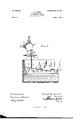
- FIG. 2 is a view showthe valve G at its upper end and against the ing the float connected to the plug-valve.
- bottom of the inlet-passage H is a spring J
- 0 represents a suitable framework, which which serves as a bufler to lessen the down is formed of a number of pieces which are force of the piston F.
- valve-seat in which a two- B by the action of the float upon the plugway rotating plug-valve A is placed.
- This valve A the steam enters the chamber R and valve A has a partially-rotating movement forces the piston F upwardly against the acand is controlled by means of a float K in a tion of the spring E.
- This upward move- 5 well or tank, as shown in Fig. 2 and this float ment of the piston F causes the valve G to is connected to the plug-valve A by means of close the outlet-pipe I, and thus throw the ina rod L, provided with a slot M at one end, jector or ejector out of operation.
- This automatic valve is to be used in connection with pumps, injectors, or ejectors for automatically feeding boilers or tanks. If used in connection with an ejector, a valve is placed in the well receiving the water to be ejected and is automatically shut off and turned on by the rise and fall of a float which is connected to the plug-valve A, as above described. When the water in the Well rises to a certain height, the float causes the plugvalve to turn to the left, thus closing the livesteam port B and opening the exhaust-port C, allowing the steam to pass out of the exhaust-pipe D.
- I claim-- 1 In an automatic valve, an inlet-pipe for the steam, a valve controlled by the action of a float, a suitable casing in which the valve is placed, and which is provided'with suitable ports for the passage of the steam, a spring-actuated piston, and a valve operated by said piston, combined with suitable inlets and outlets for the steam, which is fed to the ejector and which valves are controlled by the valve operated by the piston, and means to relieve the back pressure on the piston when the valve operated by the same is opened, substantially as shown.
- a suitable casing provided with an inlet and outlet for the steam which is fed to the ejector, inlet and outlet pipes connected to the lower part of the casing, and a two-way plug-valve which is an tomatically operated by a float, combined with the chambers R and S, formed in the casing, a spring-actuated piston placed between the said two chambers, a valve-rod connected to said piston, and a valve connected to the upper end of the said rod and controlling the feed of the steam to the ejector, substantially as described.
- a suitable casing provided with aninletandoutlet forthesteam which is fed to the ejector, a plug-valve automatically operated by a float, a chamber, a spring-actuated piston carrying a valve which controls the outlet for the steam, a port for admitting steam to the chamber and which port is controlled by the plug-valve and exhaust-ports connected with the chamber in which the piston is located, one of which is controlled by the plug-valve, substantially as described.
Description
No. 684,802. Patented Oct. 22, I901.
I .1. e. DUCK.
AUTOMATIC VALVE.
(Applicltion filed Nov. 13, 1900.) (,No Model.) 2 Sheets-Sheet I.
2 Sheets-Sheet 2.
(No Model.
rub uonms Perms 001. mowoumen wmammm a c NTTED STATES PATENT OFFICE,
JOSEPH GEORGE DUCK, OF MILWAUKEE, WVISCONSIN, ASSIGNOR OF ONE- IIALF TO WVILLIAM D. LABADIE, OF SOUTH BEND, INDIANA.
AUTOMATIC VALVE.
SPECIFICATION forming part of Letters Patent N; 684,802, dated October 22, 1961.
Application filed November 13, 1900. Serial No. 36,358. (l lo model.) I
To all whom it may concern.- the water in the well reaches a certain height Be it known that I, JOSEPH GEORGE DU OK, the float causes the valve A to turn toward a citizen of the United States, residing at Milthe left, and the valve in turning closes the waukee, in the county of Milwaukee and State steam-passage B for the admission of live 5 of Wisconsin, have invented certain new and steam and opens the lower end of the passage useful Improvements in Automatic Valves; 0, so as to allow the steam to escape through and I do hereby declare the following to be a the pipe D. The supply-pipe P is provided full, clear, and exact description of the inwith a valve Q, so that the supply of steam vention, such as will enable others skilled in can be shut off whenever so desired, and thus IO the art to which it appertains to make and the entire apparatus entirely thrown out of use the same. action. As long as the valve Q is not closed My invention relates to an improvementin the apparatus is automatically thrown into I automatic valves to be used in connection and out of action by the rise and fall of the with steam-pumps for feeding boilers, ejeclevel of the waterin the well without any care I 5 tors, or injectors; and its object is to provide whatever upon the part of the attendant.
a mechanism which is automatic in its action The live steam which passes through the and which is brought into play whenever the port B enters the steam-chamber R and bears water in a well rises to a certain height and against the lower side of the piston F, which to cease as soon as the level of the water is has a vertical movement in the casing O, and 2o lowered to the desired degree. to the upper side of which piston in the chain- Myinvention consists in a plug-valve which ber S is applied the coil-spring E for the puris controlled by the rise and fall of a float, pose of forcing the piston F downwardly as steam passages for the admission and dissoon as the pressure of steam is automatically charge of the steam, a spring-actuated piston shut off by the float connected to the plug- 25 or valve which is forced upward against the valve A. Connected to the piston F is the pressure of its spring by the steam and to valve-rod T, which passes up through a suitwhich piston or valveavalve-rodisconnected, able stuffing-box U and which has its upper combined with a casing provided with an inend made globular, as shown in the steamlet for the admittance of the steam and an passage H. 3o outlet for its discharge and a valve by which The upper portion of the casing 0 is shaped the passage of the steam to the ejector is conas shown and has the inlet H for the steam trolled, as will be more fully described hereand the outlet I, and this outlet I is controlled inafter. by the valve G, placed upon the upper end of In theaccompanyingdrawings,Figurelrepthe valve-stem T. Surrounding the valve- 3 5 resents a vertical section of a valve which emstem and bearing against the under side of bodies my invention. Fig. 2 is a view showthe valve G at its upper end and against the ing the float connected to the plug-valve. bottom of the inlet-passage H is a spring J, 0 represents a suitable framework, which which serves as a bufler to lessen the down is formed of a number of pieces which are force of the piston F. go 40 screwed together, as shown, and in its lower When steam is admitted through the port end is formed a valve-seat, in which a two- B by the action of the float upon the plugway rotating plug-valve A is placed. This valve A, the steam enters the chamber R and valve A has a partially-rotating movement forces the piston F upwardly against the acand is controlled by means of a float K in a tion of the spring E. This upward move- 5 well or tank, as shown in Fig. 2, and this float ment of the piston F causes the valve G to is connected to the plug-valve A by means of close the outlet-pipe I, and thus throw the ina rod L, provided with a slot M at one end, jector or ejector out of operation. When no i in which the arm N on the valve slides. By steam is admitted through the port B, the providing the slot in the rod L'the float will pressure of the spring E causes the piston F too 50 be allowed to rise and fall a slight distance to drop upon its seat, and the valve G is thus before operating the plug-valve. As soon as opened, so as to allow the steam to pass freely to the injector or ejector by the opening of the valve G, which is formed with a ball and socket, so as to always perfectly seat itself. At the same time that the port B is closed the port 0 is opened, so as to allow any steam in the chamber R to escape through the pipe D.
Connected with the chamber S, in which the spring E is placed, is an escape-pipe V, so that any steam finding admission to the chamber S from above or below will pass off through the pipes V D and freely escape.
This automatic valve is to be used in connection with pumps, injectors, or ejectors for automatically feeding boilers or tanks. If used in connection with an ejector, a valve is placed in the well receiving the water to be ejected and is automatically shut off and turned on by the rise and fall of a float which is connected to the plug-valve A, as above described. When the water in the Well rises to a certain height, the float causes the plugvalve to turn to the left, thus closing the livesteam port B and opening the exhaust-port C, allowing the steam to pass out of the exhaust-pipe D. The tension of the spring E being no longer overcome by the pressure of the steam forces the piston down and unseats the valve G, thus allowing the steam to enter the inlet-pipe H and pass through the outlet I to the ejector, which raises the water out of the well.
Having thus described my invention, I claim-- 1. In an automatic valve, an inlet-pipe for the steam, a valve controlled by the action of a float, a suitable casing in which the valve is placed, and which is provided'with suitable ports for the passage of the steam, a spring-actuated piston, and a valve operated by said piston, combined with suitable inlets and outlets for the steam, which is fed to the ejector and which valves are controlled by the valve operated by the piston, and means to relieve the back pressure on the piston when the valve operated by the same is opened, substantially as shown.
2. In an automatic valve, a suitable casing provided with an inlet and outlet for the steam which is fed to the ejector, inlet and outlet pipes connected to the lower part of the casing, and a two-way plug-valve which is an tomatically operated by a float, combined with the chambers R and S, formed in the casing, a spring-actuated piston placed between the said two chambers, a valve-rod connected to said piston, and a valve connected to the upper end of the said rod and controlling the feed of the steam to the ejector, substantially as described.
3. In an automatic valve, a suitable casing provided with aninletandoutlet forthesteam which is fed to the ejector, a plug-valve automatically operated by a float, a chamber, a spring-actuated piston carrying a valve which controls the outlet for the steam, a port for admitting steam to the chamber and which port is controlled by the plug-valve and exhaust-ports connected with the chamber in which the piston is located, one of which is controlled by the plug-valve, substantially as described.
In testimony whereof I afflX my signature in presence of two witnesses.
JOSEPH GEORGE DUCK.
Witnesses:
S. A. EoKsTEIN, HARRY F. HARPER.
Priority Applications (1)
| Application Number | Priority Date | Filing Date | Title |
|---|---|---|---|
| US1900036358 US684802A (en) | 1900-11-13 | 1900-11-13 | Automatic valve. |
Applications Claiming Priority (1)
| Application Number | Priority Date | Filing Date | Title |
|---|---|---|---|
| US1900036358 US684802A (en) | 1900-11-13 | 1900-11-13 | Automatic valve. |
Publications (1)
| Publication Number | Publication Date |
|---|---|
| US684802A true US684802A (en) | 1901-10-22 |
Family
ID=2753345
Family Applications (1)
| Application Number | Title | Priority Date | Filing Date |
|---|---|---|---|
| US1900036358 Expired - Lifetime US684802A (en) | 1900-11-13 | 1900-11-13 | Automatic valve. |
Country Status (1)
| Country | Link |
|---|---|
| US (1) | US684802A (en) |
Cited By (1)
| Publication number | Priority date | Publication date | Assignee | Title |
|---|---|---|---|---|
| US2614573A (en) * | 1945-05-05 | 1952-10-21 | Union Carbide & Carbon Corp | Aircraft breathing oxygen regulator |
-
1900
- 1900-11-13 US US1900036358 patent/US684802A/en not_active Expired - Lifetime
Cited By (1)
| Publication number | Priority date | Publication date | Assignee | Title |
|---|---|---|---|---|
| US2614573A (en) * | 1945-05-05 | 1952-10-21 | Union Carbide & Carbon Corp | Aircraft breathing oxygen regulator |
Similar Documents
| Publication | Publication Date | Title |
|---|---|---|
| US684802A (en) | Automatic valve. | |
| US688286A (en) | Water-feeder for boilers. | |
| US674696A (en) | Water-supply valve. | |
| US347559A (en) | blessing | |
| US1003757A (en) | Control for sewage and other pumps. | |
| US367088A (en) | Circulator and governor for pumps | |
| US338560A (en) | Beer-pump | |
| US135757A (en) | Improvement in feed-water apparatus for steam-boilers | |
| US848775A (en) | Air-compressor. | |
| US685065A (en) | Boiler-feeder. | |
| US207483A (en) | Improvement in pump-regulating valves | |
| US658728A (en) | Automatic gravity boiler-feeder. | |
| US341203A (en) | Feed-water regulator | |
| US138077A (en) | Improvement in combined stop-cocks, check-valves, and blow-offs | |
| US664183A (en) | Ejector for raising sewage or other liquids. | |
| US795329A (en) | Feed-regulator. | |
| US451130A (en) | Beer-pump | |
| US641251A (en) | Apparatus for raising water. | |
| US353776A (en) | beooks | |
| US404202A (en) | Automatic valve attachment for power mechanisms | |
| US793741A (en) | Feeder for steam-boilers. | |
| US299230A (en) | Injector | |
| US485570A (en) | Feed-water heater for steam-boilers | |
| US246089A (en) | Hydraulic air-pump | |
| US364885A (en) | bailey |