US6837173B2 - Watercraft - Google Patents
Watercraft Download PDFInfo
- Publication number
- US6837173B2 US6837173B2 US10/209,658 US20965802A US6837173B2 US 6837173 B2 US6837173 B2 US 6837173B2 US 20965802 A US20965802 A US 20965802A US 6837173 B2 US6837173 B2 US 6837173B2
- Authority
- US
- United States
- Prior art keywords
- watercraft
- engine
- hull
- disposed
- seat
- Prior art date
- Legal status (The legal status is an assumption and is not a legal conclusion. Google has not performed a legal analysis and makes no representation as to the accuracy of the status listed.)
- Expired - Lifetime, expires
Links
- XLYOFNOQVPJJNP-UHFFFAOYSA-N water Substances O XLYOFNOQVPJJNP-UHFFFAOYSA-N 0.000 claims description 42
- 239000000463 material Substances 0.000 claims description 13
- 229910052782 aluminium Inorganic materials 0.000 claims description 4
- XAGFODPZIPBFFR-UHFFFAOYSA-N aluminium Chemical compound [Al] XAGFODPZIPBFFR-UHFFFAOYSA-N 0.000 claims description 4
- 230000007797 corrosion Effects 0.000 claims description 3
- 238000005260 corrosion Methods 0.000 claims description 3
- 239000012530 fluid Substances 0.000 claims 5
- 230000007704 transition Effects 0.000 description 15
- 210000002414 leg Anatomy 0.000 description 13
- 230000036961 partial effect Effects 0.000 description 9
- 238000010276 construction Methods 0.000 description 6
- 230000002411 adverse Effects 0.000 description 5
- 238000002485 combustion reaction Methods 0.000 description 4
- 210000003127 knee Anatomy 0.000 description 4
- 229910000831 Steel Inorganic materials 0.000 description 3
- 239000000853 adhesive Substances 0.000 description 3
- 230000001070 adhesive effect Effects 0.000 description 3
- 230000000694 effects Effects 0.000 description 3
- 239000010959 steel Substances 0.000 description 3
- 239000007789 gas Substances 0.000 description 2
- 230000002452 interceptive effect Effects 0.000 description 2
- 238000004519 manufacturing process Methods 0.000 description 2
- 229910052751 metal Inorganic materials 0.000 description 2
- 239000002184 metal Substances 0.000 description 2
- 230000002940 repellent Effects 0.000 description 2
- 239000005871 repellent Substances 0.000 description 2
- 230000003466 anti-cipated effect Effects 0.000 description 1
- 230000015556 catabolic process Effects 0.000 description 1
- 238000006731 degradation reaction Methods 0.000 description 1
- 238000010586 diagram Methods 0.000 description 1
- 230000007613 environmental effect Effects 0.000 description 1
- 239000000446 fuel Substances 0.000 description 1
- 239000011521 glass Substances 0.000 description 1
- 230000003116 impacting effect Effects 0.000 description 1
- 239000003562 lightweight material Substances 0.000 description 1
- 239000007769 metal material Substances 0.000 description 1
- 238000000034 method Methods 0.000 description 1
- 230000002093 peripheral effect Effects 0.000 description 1
- 230000001681 protective effect Effects 0.000 description 1
- 230000002829 reductive effect Effects 0.000 description 1
- 239000013535 sea water Substances 0.000 description 1
- 229910001220 stainless steel Inorganic materials 0.000 description 1
- 239000010935 stainless steel Substances 0.000 description 1
- 238000010408 sweeping Methods 0.000 description 1
- 239000002759 woven fabric Substances 0.000 description 1
Images


Classifications
-
- B—PERFORMING OPERATIONS; TRANSPORTING
- B63—SHIPS OR OTHER WATERBORNE VESSELS; RELATED EQUIPMENT
- B63B—SHIPS OR OTHER WATERBORNE VESSELS; EQUIPMENT FOR SHIPPING
- B63B11/00—Interior subdivision of hulls
-
- B—PERFORMING OPERATIONS; TRANSPORTING
- B63—SHIPS OR OTHER WATERBORNE VESSELS; RELATED EQUIPMENT
- B63B—SHIPS OR OTHER WATERBORNE VESSELS; EQUIPMENT FOR SHIPPING
- B63B17/00—Vessels parts, details, or accessories, not otherwise provided for
- B63B17/02—Awnings, including rigid weather protection structures, e.g. sunroofs; Tarpaulins; Accessories for awnings or tarpaulins
-
- B—PERFORMING OPERATIONS; TRANSPORTING
- B63—SHIPS OR OTHER WATERBORNE VESSELS; RELATED EQUIPMENT
- B63B—SHIPS OR OTHER WATERBORNE VESSELS; EQUIPMENT FOR SHIPPING
- B63B3/00—Hulls characterised by their structure or component parts
- B63B3/14—Hull parts
- B63B3/48—Decks
Definitions
- the present invention relates to the deck layout for a boat. More specifically, the present invention concerns the deck layout for a sport boat.
- Boats designed for leisure generally include yachts and other types of boats that are provided with a cabin or enclosed compartment for the boat's occupants.
- Boats designed for sportier activities generally do not incorporate a cabin or enclosed passenger space, because such boats typically are limited in their construction by constraints placed upon the total weight of the vehicle.
- Sport boats are characterized by a number of features common to that vehicle's genre. In particular, sport boats are designed to travel across the water's surface at high speed. To accomplish this, sport boats incorporate powerful engines connected to propulsion devices such as jet propulsion units.
- a jet propulsion unit incorporates an impeller housed at the rear of the vehicle. The impeller draws water through a water passage under the vehicle, pressurizes the water, and discharges the water from the rear of the vehicle to propel the vessel.
- sport boats are capable of generally greater speeds than leisure craft, they are often used for a number of different sporting activities such as water skiing, wake boarding, knee boarding, etc.
- sport boats traditionally have been designed to maximize speed and maneuverability while minimizing deck space (thereby minimizing boat weight)
- a need has developed for a sport boat with increased accessibility to a storage space, especially for accessibility to a space (or spaces) large enough to hold sporting equipment such as water skis, wake boards, knee boards, and fishing poles, among other types of equipment.
- An open deck boat is one where the entire deck of the boat may be viewed from the exterior of the vessel. In other words, there is no internal cabin or enclosed space within the boat where riders may retire in shade (or be protected from the elements, such as rain). Since sport boats are designed primarily with speed and maneuverability in mind, the addition of shade features, such as canopies, traditionally has been antithetical to sport boat design, because the additional structure either adds weight to the vehicle or provides further drag when the vehicle is in motion. However, a need has developed for the design of a sport boat that can provide at least modest protection for riders from the elements without detracting from the speed, maneuverability, or appearance of the sport boat.
- resonator canister(s) should be disposed substantially horizontally within the hull. This does not facilitate removal of water that may accumulate with the resonator canister(s), a condition that may affect adversely the performance of the watercraft. Accordingly, a need has developed for a component layout that facilitates removal of water from the resonator canister(s).
- Some sport boats also suffer from at least one additional failing in the prior art.
- some sport boats traditionally incorporated a large, curved transition between the rear transom of the watercraft and the bottom of the hull (the running surface of the boat).
- Such a large, slowly-sweeping transition creates a large radius of curvature between the rear of the vessel and the operative surface at the bottom of the hull, which, in some cases, adversely affects the operation of the vessel.
- the large radius of curvature results in increased drag on the hull.
- a need has developed for a hull design that minimizes drag on the hull at the transition between the transom at the stern of the vessel and the operating surface beneath the hull.
- the sound system should be designed with an anti-theft device to prevent, or at least deter, theft of the radio, CD player, or other sound equipment placed on the vessel.
- the passenger's seat is typically the seat adjacent to the driver's seat but on the opposite side of the boat. In some boat designs, the driver's seat and the passenger's seat are positioned in front of a bench seat that extends across the rear of the vessel from the port to starboard sides.
- the sound system In the case where the sound system is positioned on the console in front of the passenger's seat, the sound system is usually exposed and visible from the exterior of the vessel. Positioned in this manner, the sound system is a particularly attractive nuisance to the average radio thief. What the prior art lacks is a reliable security device or system that either reduces or eliminates the theft potential for the sound system aboard vessels with an open deck.
- the prior art fails to provide foot rest areas for passengers that can accommodate a variety of foot positions and/or different heights of individuals.
- the vessel includes compartments at least for the storage of large sporting equipment such as water skis, wake boards, and knee boards, among others.
- the rear bench is divided into one or more removable sections that, when lifted from above the storage compartment, expose the storage compartment.
- one aspect of the present invention is to provide a boat with a powered hull defining lateral and longitudinal directions.
- a deck is disposed above the hull.
- a storage compartment is provided in the deck. The storage compartment extends laterally across a substantial width of the hull and is substantially larger in the lateral direction than in the longitudinal direction.
- the wall helps to define the storage spaces laterally adjacent to the engine.
- the wall is removable to permit access to the sides of the engine.
- one aspect of the present invention is to provide a boat with a hull having a transom.
- An engine for propelling the boat is mounted to the hull forward of the transom.
- a storage compartment is positioned on the hull on a lateral side of the engine.
- a removable wall portion is disposed between the engine and the storage compartment. The removal of the wall portion facilitates access to the engine through the storage compartment.
- a deployable sunshade such as a canopy.
- the sunshade is easily stowed within the engine compartment so that it does not adversely impact on the aesthetic appearance of the vessel.
- the sunshade is easily deployed from its stowed position without the need to assemble and attach complex, rigid supports to the deck.
- one aspect of the present invention is to provide a sport boat with a sun shade (e.g., a canopy) that may be folded and stowed on the sport boat without having to detach the canopy supports from the sport boat.
- a sun shade e.g., a canopy
- the present invention provides a boat with a hull and a deck. Port and starboard gunwales define port and starboard sides.
- a canopy system is provided that includes starboard and port longitudinally extending slide rails mounted to the starboard and port gunwales, respectively.
- the canopy system includes a canopy support having a starboard end pivotally and slidably mounted to the starboard slide rail and a port end pivotally and slidably mounted to the port slide rail. It also includes a canopy mounted to the canopy support.
- the canopy system is selectively movable between raised and stowed positions. Moreover, when the canopy system is in the stowed position, a middle portion of the canopy support is concealed from view. When the canopy system is in the raised position, the middle portion of the canopy support is disposed above the deck.
- One other aspect of the present invention is to provide a hull design that minimizes drag at the transition between the transom and the operational surface on the bottom of the hull.
- a surface is provided that is disposed at an angle of forty-five degrees to the bottom surface of the hull and to the transom that acts as an intermediate surface between these two surfaces and that minimizes drag.
- the present invention provides a boat having a hull with a bottom exterior side that defines a running surface and a stern exterior side.
- An engine is disposed within the hull.
- An intersecting surface extends between the bottom exterior side and the stern exterior side. The intersecting surface forms a predetermined angle with respect to the bottom exterior side.
- a further aspect of the present invention is to provide a sport boat with a windshield that does not interfere with the driver's side vision.
- the present invention improves the driver's field of vision on both the starboard and port sides of the vessel.
- one aspect of the present invention is to provide a windshield that extends to a height on the sides of the vessel that is less than the height of the windshield at the front of the vessel.
- the present invention provides a boat with a hull having side gunwales.
- the engine is disposed within the hull for propulsion.
- a control console is operatively connected to the engine to control the engine.
- a driver's seat is disposed on the hull behind the control console.
- a front windshield is mounted to the hull and extends upwardly a predetermined height from the hull in front of the driver's seat for protection of a driver from wind.
- Port and starboard side windshields are adapted to provide a windscreen for the driver.
- the side windshields extend upwardly from the gunwales with forward ends of the side windshields being connected to the front windshield.
- the side windshields extend rearwardly behind the driver's seat when the driver's seat is in a driving position.
- the tops of the side windshields are disposed below the predetermined height of the front of the windshield, improving the field of visibility for the driver.
- Another aspect of the present invention is to provide a console cover at least on the console in front of the passenger seat.
- the console cover may be raised to expose the radio or sound system therebeneath. Since the cover can be closed, the cover provides additional security protection for the radio or sound system components covered thereby.
- one object of the present invention is to provide a hinge assembly that permits the console cover to be opened without interfering with the windshield disposed above it.
- a further aspect of the present invention is to provide an improved positioning for the engine components, in particular, the muffler(s) or resonator canister(s). More specifically, in one example, the resonator canister(s) are positioned to facilitate draining of water that may accumulate therein.
- one aspect of the present invention is to provide a boat with a hull, a deck disposed above the hull, and a transversely extending transom.
- An engine is mounted in the boat for propulsion of the boat, the engine having an exhaust port.
- At least one resonator canister is operatively connected to the exhaust port of the engine and is disposed in front of the transom.
- the resonator canister exhausts to an external side of the hull.
- the resonator canister is mounted in front of the transom such that one end is lower than the other.
- One further aspect of the present invention is to provide a foot rest area that provides for different foot positions and accommodates individuals of different heights.
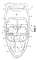
- FIG. 1 is a top view of a watercraft incorporating at least one of the features of the present invention
- FIG. 2 is a perspective illustration of the boat shown in FIG. 1 ;
- FIG. 3 is a perspective view of a boat incorporating one or more aspects of the present invention, the illustration showing the engine cover of the watercraft in an open position;
- FIG. 4 is a partial perspective illustration of a portion of the watercraft illustrated in FIG. 1 , the view being from the rearward passenger area looking toward the rear of the boat with the engine cover opened;
- FIG. 5 is another partial perspective illustration of a portion of the watercraft illustrated in FIG. 1 , the view being from the rearward passenger area looking toward the rear of the boat with the engine cover opened, the perspective illustrating the position of a secondary engine cover in a closed position;
- FIG. 6 is another partial perspective illustration of the watercraft illustrated in FIG. 1 , the view looking toward the port side of the watercraft from a vantage point in the rearward passenger area near the starboard stern of the watercraft;
- FIG. 7 is a partial perspective view of the interior of the watercraft illustrated in FIG. 1 , the view facing the starboard side of the watercraft from a vantage point within the rearward passenger area of the watercraft;
- FIG. 8 is a perspective illustration of the watercraft shown in FIG. 1 fitted with a first embodiment of a canopy, known as a “convertible canopy”;
- FIG. 9 is a perspective view of a portion of the watercraft, depicting the convertible canopy illustrated in FIG. 8 , shown here with the protective side and rear panels removed;
- FIG. 10 is a side view of a portion of the watercraft, showing the convertible canopy of FIGS. 8 and 9 from a side perspective;
- FIG. 11 is a perspective illustration of the watercraft shown in FIG. 1 fitted with a second embodiment of a canopy known as a “bimini canopy,” which provides a greater amount of headroom than the “convertible canopy” embodiment illustrated in FIG. 8 ;
- FIG. 12 is a partial perspective view of a storage compartment in the watercraft illustrated in FIG. 1 , the storage compartment being located beneath the rear bench seat of the watercraft, the seat cushion(s) of which have been removed in this illustration to show the interior of the storage compartment;
- FIG. 13 is a cross-sectional, schematic representation of the storage compartment illustrated in FIG. 12 ;
- FIG. 14 is a perspective illustration of the port console (passenger's console) of the watercraft illustrated in FIG. 1 , shown with the console cover in a closed position;
- FIG. 15 is a perspective illustration of the port console of the watercraft shown in FIG. 14 , shown with the console cover in an opened position;
- FIG. 16 is an enlarged, partial perspective illustration of the port console of the watercraft shown in FIG. 14 , illustrating in detail the hinge beneath the console cover that permits the cover to opened beneath the windshield of the watercraft;
- FIG. 17 is a partial perspective illustration of the watercraft shown in FIG. 1 , the view facing the port of the watercraft from an interior vantage point, the view illustrating the curvature of the side portion of the windshield;
- FIG. 18 is a partial perspective illustration of the underside of the stern of the watercraft as illustrated in FIG. 1 , the view being of the rear most portion of the hull at the transition from the bottom of the hull to the transom at the rear of the watercraft;
- FIG. 19 is a partial cross-sectional view of the hull of the watercraft illustrated in FIG. 1 , the cross-section being taken at the transition point between the bottom surface and the rear transom of the hull;
- FIG. 20 is a top schematic view of a first embodiment of the engine and resonator canister arrangement for the watercraft illustrated in FIG. 1 ;
- FIG. 21 is a top schematic view of a second embodiment of the engine and resonator canister arrangement for the watercraft illustrated in FIG. 1 ;
- FIG. 22 is a perspective view a table positioned within the passenger area
- FIG. 23 is a perspective view of the table, in a disassembled state, stored over the secondary engine cover;
- FIG. 24 is a side view of a foot rest portion for the watercraft illustrated in FIG. 1 ;
- FIG. 25 is a perspective view of the foot rest portion shown in FIG. 22 , showing the passenger's feet in a first position;
- FIG. 26 is a perspective view of the foot rest portion shown in FIG. 22 , showing the passenger's feet in a second position.
- FIG. 1 is a top view of the watercraft 10 of the present invention. While the watercraft 10 is depicted with a specific configuration, as described more fully below, those skilled in the art will appreciate that one or more of the aspects of the present invention may be incorporated into a watercraft, regardless of the particular configuration and layout. In other words, aspects of the present invention are intended for use on watercraft and are not limited solely to the watercraft 10 depicted and described.
- the watercraft 10 includes a hull 12 with a bow 14 and a stern 16 .
- the layout of the deck 18 includes a forward passenger area 20 and a rearward passenger area 22 .
- the forward passenger area 20 is connected to the rearward passenger area 22 by a passageway 24 .
- a windshield 26 extends from the port side 28 to the starboard side 30 of the watercraft 10 .
- a center section 32 of the windshield 26 is openable to permit riders to move about on the deck 18 from the forward passenger area 20 to the rearward passenger area 22 .
- the center section 32 of the windshield 26 may be closed to provide a wind screen for the riders in the rearward passenger area 22 .
- the center section 32 preferably is hingedly mounted to the remainder of the windshield 26 on either the port or starboard sides 28 , 30 . If the hinge is positioned on the port side 28 of the center section 32 of the windshield 26 , the center section 32 will fold outwardly against the port side 28 of the windshield 26 when opened. If the hinge is positioned on the starboard side 30 of the windshield 26 , the center section 32 will fold over onto the starboard side 30 of the windshield 26 when opened. Alternatively, the center section 32 of the windshield 26 may be removable altogether. In addition, while a center section 32 is preferred for the windshield 26 , the center section 32 is not required to practice aspects of the present invention.
- the illustrated watercraft 10 is rated to accommodate eight passengers.
- the forward passenger area 20 there are two seats, a forward port seat 34 and a forward starboard seat 36 .
- Both the forward port seat 34 and the forward starboard seat 36 preferably are integrally molded as part of the deck 18 .
- Both seats 34 , 36 are designed to accommodate one adult-sized rider.
- the rearward passenger area 22 includes a port buddy seat 38 and a starboard buddy seat 40 .
- the buddy seats 38 , 40 are so named because they are designed to accommodate two adult-sized riders each.
- a bench 42 which is also an integral part of the deck 18 , is positioned behind the two buddy seats 38 , 40 and is designed to accommodate up to four adult-sized riders.
- the buddy seats 38 , 40 are shown in the driving position.
- the buddy seats 38 , 40 are shown in a forward-facing position behind the port console 44 and the starboard console 46 .
- the starboard console 46 includes a steering wheel 48 .
- the port buddy seat 38 is rotatable in the direction shown by arrow 50 .
- the starboard buddy seat 40 is rotatable in the direction indicated by arrow 52 .
- the buddy seats 38 , 40 When the watercraft 10 is at rest, the buddy seats 38 , 40 may be rotated approximately 90 degrees from a driving position to a relaxed position so that the back rests for the seats 38 , 40 abut against the port and starboard gunwales 56 , 54 of the watercraft 10 .
- the seats 38 , 40 When the seats 38 , 40 are rotated to the relaxed position, the seats 38 , 40 mate with the bench seat 42 at the rear of the rearward passenger area 22 to form a substantially contiguous seating area.
- the seats 38 , 40 are rotated against the gunwales 54 , 56 and the center portion 32 of the windshield 26 is opened, riders may move freely from the forward passenger area 20 to the rearward passenger area 22 and vice versa.
- the buddy seats 38 , 40 when the buddy seats 38 , 40 are rotated against the gunwales 54 , 56 , the rearward passenger area 22 is maximized in terms of its useable space.
- buddy seats 38 , 40 are preferred for the watercraft 10 of the present invention, the buddy seats 38 , 40 are not required. Instead, prior art bucket seats may be substituted therefor. If buckets seats are incorporated into the driver's and passenger's positions, the overall capacity of the sport boat 10 is reduced by two passengers since bucket seats are designed to accommodate only one adult-sized rider.
- FIG. 2 illustrates the engine cover 58 in a closed position where the cover 58 encloses the engine 60 and other peripheral features at the stern 16 of the watercraft 10 .
- the watercraft 10 is powered by an internal combustion engine 60 .
- the internal combustion engine may be either of the two or four stroke variety.
- the engine 60 need not be an internal combustion engine, but any alternative engine 60 may be substituted therefor without deviating from the scope of the present invention.
- the engine 60 could be replaced by an electrically-driven motor powered by batteries or a fuel cell.
- the watercraft 10 preferably is powered by a jet propulsion unit.
- the jet propulsion unit is disposed at the stern 16 of the watercraft in the same general location as the engine 60 .
- the jet propulsion unit is designed to draw water from underneath the hull 12 of the watercraft, pressurize the water (by an impeller), and discharge the water at great pressure through a jet port at the stern 16 of the watercraft 10 .
- a jet propulsion unit is the preferred choice for propelling the watercraft 10 , those skilled in the art would appreciate that the watercraft 10 could be propelled alternatively with a propeller driven by an inboard internal combustion engine or by one or more outboard propeller motor.
- the engine cover 58 preferably forms the back rest 62 for the rear bench seat 42 . As shown in detail in FIG. 4 , the engine cover 58 preferably is mounted with one or more hinges 66 to the stern 16 of the watercraft 10 above the engine 60 . When opened, the engine cover 58 preferably is held upright by one or more pistons 64 .
- the engine cover 58 will be manually opened by releasing a latch 68 beneath the cover 58 .
- the latch 68 engages a pin 70 disposed on the deck 18 behind the bench seat 42 .
- the engine cover 58 need not be constructed such that it is opened manually.
- the engine cover 58 could be constructed so that it is opened electro-mechanically from a switch, which may be disposed on either the port or starboard control consoles 44 , 46 , for example.
- the engine cover 58 covers not only the engine 60 , but it also covers port and starboard storage compartments 72 , 74 .
- the port and starboard storage compartments 72 , 74 straddle the engine 60 on either side.
- both of the storage compartments 72 , 74 preferably are integrally molded as part of the deck 18 .
- the storage compartments 72 , 74 need not be integrally molded with the deck 18 . Instead, they may be provided as inserts into the deck 18 .
- Port and starboard wall inserts 82 , 84 separate the port storage compartment 72 and the starboard storage compartment 74 from the engine 60 .
- the port and starboard wall inserts 82 , 84 are constructed from a light-weight plastic material and are fastened to the deck 18 with bolts or other suitable, removable fasteners.
- the wall inserts 82 , 84 are preferably fitted with a reflective and insulative material 86 on the side facing the engine 60 , which prevents the heat generated by the engine 60 from adversely affecting the items stored in either of the compartments 72 , 74 .
- a secondary engine cover 71 may be positioned above the engine 60 , extending between the port and starboard wall inserts 82 , 84 . With such a construction, upon opening the engine cover 58 , the engine 60 would not be accessible immediately. The secondary engine cover 71 would be required to be removed (or opened) to provide access to the engine 60 . It is contemplated that the secondary engine cover 71 could be pivotally attached to the port or starboard wall inserts 82 , 84 , or the rear side 78 of the engine compartment. It is also contemplated that the secondary engine cover 71 could be provided with one or more depressions for storage of items above the engine 60 . For example, the secondary engine cover 71 could be provided with a storage area for tools or a first aid kit, among other items.
- the port and starboard wall inserts 82 , 84 preferably are easily removed from the positions illustrated in FIGS. 4-6 . When removed, access to the engine 60 is greatly facilitated. While screws or bolts are preferred to removably fasten the wall inserts 82 , 84 adjacent to the engine, any suitable fastener may be used as would be understood by those skilled in the art.
- FIGS. 4-5 and 7 - 10 illustrate various aspects of two canopy options contemplated for use on the watercraft 10 of the present invention.
- the first canopy option is the “low headroom” option (canopy 88 ) and is illustrated in FIGS. 8-10 .
- This “low headroom” option is more commonly referred to as a “convertible canopy” 88 .
- the second canopy option is the “high headroom” option (canopy 90 ) illustrated in FIG. 11 .
- This “high headroom” option is more commonly referred to as a “bimini canopy” 90 .
- Both the convertible canopy 88 and the bimini canopy 90 serve the same purpose. Specifically, both canopies 88 , 90 protect riders in the rearward passenger area 22 from the elements, such as sunshine or rain. Alternatively, the canopies 88 , 90 may be used to protect the watercraft 10 when it is not in used but is docked.
- Both canopies 88 , 90 are designed to store easily within the deck 18 of the watercraft 10 . Specifically, as illustrated in FIGS. 4 and 5 , the canopy 88 , 90 folds to be compactly stored beneath the engine cover 58 .
- the watercraft 10 incorporates slide rails 92 on either side of rearward passenger area 22 .
- the slide rails 92 accommodate the supporting braces 94 for the canopy 88 , 90 .
- the supporting braces 94 are pivotally and slidably mounted in the slide rails 92 , as shown in FIG. 7 .
- at least one supporting brace 94 is provided to support the canopy 88 , 90 , as illustrated in FIGS. 4 and 5 .
- the supporting brace(s) 94 are U-shaped and extend from the slide rail 92 on one side of the rearward passenger area 22 to the slide rail 92 on the other side.
- the canopy 88 , 90 folds so it can be conveniently stored beneath the engine cover 58 , as illustrated in FIGS. 4 and 5 .
- the canopy 88 , 90 may be deployed from its storage position beneath the engine cover 58 .
- One particular advantage offered by the design of the canopy 88 , 90 and the slide rails 92 lies in the fact that the canopy 88 , 90 may be folded and stored beneath the engine cover 58 without the need for detaching the supporting brace(s) 94 from the slide rails 92 . This greatly facilitates deployment and storage of the canopy 88 , 90 .
- the canopies 88 , 90 are affixed to the deck 18 of the boat and the windshield 26 through conventional snap fasteners 95 so that canopies 88 , 90 may be quickly erected and/or prepared for storage beneath the engine cover 58 .
- the canopies 88 , 90 may be attached to the watercraft 10 using any other suitable means.
- the canopies 88 , 90 are constructed from a woven material that has been treated to be water resistant or water repellent.
- a woven material that has been treated to be water resistant or water repellent.
- any suitable material may be used in place of the preferred woven fabric.
- a non-woven, water resistant (or water repellent) material may be used.
- the interior surface 59 of the engine cover 58 preferably is a finished surface on the watercraft 10 .
- the interior surface 59 of the engine cover preferably is finished as a “Class A” surface, which is a quality standard typically reserved for an exterior portion of the watercraft 10 .
- Such a finish is preferred for the interior surface 59 of the engine cover 58 because the cover 58 is expected to be opened frequently to access the storage compartments 72 , 74 and the canopy 88 , 90 .
- FIG. 12 illustrates a lateral ski bucket storage compartment 96 concealed beneath the cushion(s) of the rear bench seat 42 within the rearward passenger area 22 .
- the lateral bucket 96 extends nearly the full width of the rear bench 42 . It also extends nearly the full width of the watercraft 10 at the location of the rear bench seat 42 .
- the lateral ski bucket 96 has a lateral length that is at least 3 ⁇ 4 of the beam of the sport boat 10 .
- the lateral ski bucket 96 has a longitudinal length that is less than half of the compartment's lateral length. So dimensioned, the lateral storage compartment 96 maximizes use of the space beneath the rear bench seat 42 .
- the lateral storage bucket 96 is designed to be large enough to easily accommodate a pair of water skis, a wake board, or similar water sport equipment.
- FIG. 13 A cross-sectional schematic diagram of the lateral storage bucket 96 is provided in FIG. 13 .
- the lateral storage bucket 96 extends beneath the rear bench seat 42 and is positioned within the boat 10 such that one end of the lateral storage bucket 96 extends a greater distance beneath the rear bench seat 42 than the opposite side.
- the opening 97 into the lateral storage bucket 96 while substantially centered beneath the cushions of the rear bench seat 42 , is not laterally co-extensive with the lateral storage bucket 96 .
- the length of the lateral storage bucket 96 permits storage of items, such as water skis, wake boards, knee boards, and fishing poles, all of which potentially have a length greater than that of the opening 97 beneath the cushions of the rear bench seat 42 . Accordingly, if the lateral width of the lateral storage bucket 96 were the same as that of the opening 97 , certain items would not fit into the lateral storage bucket 96 .
- FIG. 13 illustrates one particular example. There, a wake board 99 , with a length that exceeds the width of the opening 97 , has been placed into the lateral storage bucket 96 . As may be readily appreciated, if the lateral storage bucket 96 did not have one side that extended a further distance into the hull 12 than the other side, the wake board 99 could not have been stored therein.
- the present invention is not limited solely to such a construction.
- the lateral storage bucket 96 is offset from the opening 97 so that its starboard end exceeds the width of the opening 97 . While it is believed that this orientation facilitates access to the contents of the lateral storage bucket 96 , it is contemplated that the lateral storage bucket 96 could exceed the width of the opening 97 on both the port and starboard sides without departing from the scope of the present invention.
- the lateral ski bucket 96 is covered by one or more seat cushions that form the seating portion of the bench seat 42 on the watercraft. While not shown in detail, the cushion or cushions preferably are fitted with protrusions on their lower surface that are designed to engage to opening 97 to the lateral ski bucket 96 . As a result, the seat cushion(s) above the lateral ski bucket 96 may be removed and replaced with minimal effort.
- the lateral ski bucket 96 is preferably integrally molded as part of the deck 18 of the watercraft 10 , those skilled in the art would readily appreciate that the body of the lateral ski bucket 96 , including the front, rear, port, starboard, and bottom sides, may be molded separately from the deck 18 of the watercraft and inserted into the deck 18 during manufacture. Additionally, the lateral ski bucket 96 need not be installed permanently within the deck 18 . Instead, the lateral ski bucket 96 may be removable to provide access to the electrical and mechanical systems within the watercraft 10 . This embodiment is illustrated in FIG. 13 .
- the port console 44 is illustrated in greater detail in FIGS. 14-16 .
- the port console is positioned forward of the port buddy seat 38 behind the windshield 26 .
- the port console 44 includes a base portion 96 and a top portion 98 .
- the top portion 98 is hingedly articulated to the base portion 96 to permit the top portion 98 to be opened by riders on the watercraft 10 .
- a support brace 100 may extend from the console 44 to the windshield 26 to provide additional rigidity and support for the windshield 26 .
- FIG. 14 shows the top portion of the console 44 in the closed position.
- FIG. 15 illustrates the top portion 98 in the opened position, exposing a radio and CD player 102 that is disposed within the bottom portion 96 of the port console 44 .
- the top portion (console cover) 98 may be provided with a lock so that the console cover 98 may be locked when the watercraft 10 is unattended, thus deterring theft of the radio and CD player 102 concealed thereunder.
- FIG. 16 illustrates a hinge 104 that permits the top portion 98 of the port console 44 to be opened without interfering with the windshield 26 .
- the hinge 104 is designed to permit the top portion 98 of the port console 44 to pivot upwardly while also permitting the rear portion of the console cover 98 to slide rearward toward the port buddy seat 38 . It is preferred that the hinge 104 operates in this manner to prevent the top portion 98 of the port console from hitting the windshield 26 with a sufficient force when the console cover 98 is opened to break or damage the windshield 26 .
- the hinge 104 includes a slide rail 106 , which is affixed to the bottom portion 96 of the port console 44 .
- the cover 98 is affixed, preferably by several fasteners 108 , to a slide member 110 .
- the slide member 110 is held in the slide rail 106 by a dowel 112 (or similar structure) that is disposed with a track (not shown) within the slide rail 106 .
- the dowel 112 permits the lower portion of the slide member 110 to slide in the directions shown by the arrows 114 , 115 .
- the slide member 110 is also pivotally connected to a support member 116 at a pivot point 118 .
- the support member 118 is pivotally connected to the slide rail 106 through a pivot 120 .
- the hinge 104 operates in the following manner.
- the console cover 98 is opened as illustrated in FIGS. 15 and 16 .
- the dowel 112 slides in the direction indicated by the arrow 114 .
- the slide member 110 is disposed at an angle with respect to the support member 116 .
- the console cover 98 therefore, is supported primarily by the support member 116 .
- the rider applies pressure to the console cover 98 so that dowel 112 slides in the slide rail 106 toward the windshield 26 in the direction of the arrow 115 .
- the slide member 110 moves downwardly toward the slide rail 106 in the direction of the arrow 120 (the arrow 122 indicating the upward motion).
- the support member 116 moves downwardly toward the slide rail 106 in the direction indicated by the arrow 124 (the arrow 126 indicating the upward motion).
- a rider applies pressure to the forward edge of the console cover 98 and the hinge 104 opens in a direction opposite to the closing direction. Because the rear portion of the slide member 110 is permitted to slide within the slide rail 106 , the console cover 98 is prevented from impacting (and potentially damaging) with the windshield 26 .
- the slide rail 106 , slide member 110 , and support member 116 are all preferably made from a corrosion-resistant material such as aluminum. However, as will be appreciated by those skilled in the art, the slide rail 106 , slide member 110 , and support member 116 may be made from a sufficiently rigid material, such as plastic, stainless steel, etc., if desired.
- FIG. 17 illustrates a portion of the windshield 26 , which wraps around a forward portion of the rearward passenger compartment 22 .
- Windshield 26 extends at least partially adjacent to the port buddy seat 38 and the starboard buddy seat 40 to define side portions 128 .
- the side portions 128 provide some protection from the wind for riders seated in either of the buddy seats 38 , 40 .
- the side portions 128 of the windshield 26 do not extend to the same height as windshields 26 in the prior art. Instead, the side portions 128 include a dip portion 130 that extends to a lower height than the front portion of the windshield 26 .
- the dip portion 130 improves visibility of objects in the water for riders within the rearward passenger area 22 , because objects in the water are not occluded by the frame 132 that surrounds the glass 134 in the windshield 26 .
- the dip 130 in the side portions 128 of the windshield 26 be a smoothly-curved structure on the windshield 26
- the dip 130 may be more angular without departing from the present invention.
- the height of the dips 130 above the sides of the watercraft 10 are sufficiently low that a rider seated in either buddy seat 38 , 40 may look over the frame 132 without having to stand up.
- the height therefore, accommodates what designers refer to as a standard rider, which is a 50 th percentile North American Male.
- the standard rider is known to those skilled in the art and is used when designing vehicles to size various aspects of those vehicles.
- the distance from the starboard buddy seat 40 to the steering wheel 48 is determined by the dimensions of the standard rider who is “placed” (at least mathematically) within the starboard buddy seat 40 during the design phase of the development of the watercraft 10 .
- FIG. 18 illustrates the rearward most portion of the sport boat 10 .
- FIG. 18 illustrates the rear transom 136 of the watercraft 10 and the transition surface 138 to the bottom 140 of the hull 12 .
- the rear transom 136 is the vertical surface at the stern 16 of the hull 12 .
- FIG. 18 also shows a portion of the ride plate 142 disposed at the stern 16 of the sport boat 10 .
- the stop cocks 144 which permit water to be drained from the interior of the hull 12 when the sport boat 10 has been removed from the water, also can be seen in FIG. 18 .
- a portion of the directional nozzle 146 which directs the flow of water from the jet propulsion system to steer the watercraft 10 , is shown.
- the transition surface 138 is disposed at an angle ⁇ to the bottom 140 of the hull 12 .
- the angle of transition was either 90 degrees or was a slowly curving surface (i.e., a surface with a large radius of curvature).
- a surface with a large radius of curvature was a problem encountered in boats that incorporated a surface with a large radius of curvature at the transition between the bottom 140 of the boat and the rear transom 136 .
- the drag was large enough to adversely affect operation of the boat, at least under certain circumstances.
- the transition surface 138 is disposed at an angle ⁇ to the bottom 140 of the hull 12 .
- the flat transition surface 138 does not create drag on the hull 12 as did the prior art transition surface with a large radius of curvature.
- the angle ⁇ is about 45 degrees. However, as would be appreciated by those skilled in the art, the angle could be within any range suitable to prevent, or at least minimize drag on the hull 12 .
- a surface with a small radius of curvature should be positioned in the same location as the transition surface 138 .
- current manufacturing techniques do not readily permit such a construction.
- a 45 degree angle for the transition surface 138 is employed.
- a small radius of curvature is preferred, because it is believed that a small radius of curvature permits the water to break away from the stern of the hull 12 more easily, thereby minimizing drag on the hull 12 .
- a large radius of curvature allows the water to follow the contours of the hull 12 , thereby increasing drag on the hull 12 .
- FIGS. 20 and 21 provide simple schematic views of the engine and resonator canister arrangements for the sport boat 10 of the present invention.
- Resonator canisters are also commonly referred to as mufflers, although the term “resonator canister” is considered to be broader than the term “muffler.”
- the terms “muffler” and “resonator canister” are meant to be interpreted as broadly as possible.
- the engine 60 which sits over the water passage 148 , is connected to a port resonator canister 150 and a starboard resonator canister 152 through a port manifold 154 and a starboard manifold 156 , respectively.
- the water passage 148 extends from an inlet at the bottom of the hull 12 (at a position forward of the stern 16 ) to an outlet at the rear of the watercraft 10 . Water is drawn into the inlet by the impeller within the water passage 148 and discharged through the outlet at great pressure to propel the watercraft 10 .
- FIGS. 20 and 21 illustrate port and starboard manifolds 154 , 156 connected to the resonator canisters 150 , 152 , those skilled in the art would recognize that this is not the only configuration possible or desired.
- the engine 60 may be provided with a single manifold to which both resonator canisters 150 , 152 are connected.
- the resonator canisters need not be connected to the engine 60 in parallel, but could be connected to the engine 60 in series, as desired.
- the port and starboard resonator canisters 150 , 152 direct exhaust gases from the engine 60 into the water tunnel 148 through port and starboard exhaust pipes 158 , 160 .
- the resonator canisters 150 , 152 direct the exhaust gases from the engine 60 toward the rear of the watercraft 10 through port and starboard exhaust pipes 162 , 164 .
- the exhaust pipes 158 , 160 empty the exhaust from the engine 60 directly into the water.
- the exhaust pipes 162 , 164 similarly may be positioned so that the exhaust from the engine 60 is directed in to the water. However, the exhaust pipes 162 , 164 may discharge the exhaust directly into the atmosphere, if desired.
- the position of the resonator canisters 150 , 152 is one aspect of the present invention.
- the resonator canisters 150 , 152 are positioned rearwardly of the engine 60 and are oriented so that their longitudinal axes are not substantially parallel to the centerline 166 of the watercraft 10 as in the prior art.
- the resonator canisters 150 , 152 are oriented so that their longitudinal axes are substantially perpendicular to the centerline 166 of the watercraft 10 .
- the resonator canisters 150 , 152 provide considerable additional room for storage within the watercraft 10 , because the resonator canisters 150 , 152 do not occupy valuable space adjacent to the engine 60 , which is where they are normally positioned.
- the resonator canisters 150 , 152 are angled so that their discharge ends are lower than their inlet ends. This permits any water that may have entered the resonator canisters 150 , 152 to drain from the resonator canisters 150 , 152 both during and after operation of the engine 60 .
- FIG. 22 illustrates one additional aspect of the present invention, a stowable table 168 .
- the stowable table 168 includes a table top 170 , which is oval in the embodiment illustrated.
- the table top 170 sits atop a table leg 172 , which has been inserted into a support bracket 174 mounted on the deck in the rearward passenger area 22 between the two buddy seats 38 , 40 .
- the table top 170 and the table leg 172 preferably are made of a light weight material such as plastic.
- the table top and leg may be made of any suitable material, so long as the material resists degradation when exposed to environmental conditions such as sun, rain, and sea water.
- the bracket 174 preferably is made of a metal material, such as steel, and is attached to the floor of the rear passenger area 22 with one of more bolts 176 .
- the bracket 174 is semi-permanently attached to the floor of the rearward passenger area 22 and is flush with the floor so that passengers within the watercraft 10 do not trip over the bracket 174 . Being semi-permanently attached to the floor, the bracket 174 may be removed from the floor of the rearward passenger area 22 . However, it is contemplated that the bracket 174 will remain attached to the floor during the operational lifetime of the watercraft 10 .
- the table leg 172 preferably is a cylindrical element where the bottom end fits within a central hole (not shown) in the bracket 174 , the top end of the leg 170 fits within a bracket 178 affixed to the bottom of the table top 170 , which is illustrated in FIG. 23 . Therefore, when the watercraft 10 is not in motion and the buddy seats 38 , 40 are rotated to their relaxed positions, as shown in FIG. 22 , the table leg 172 may be inserted into the bracket 174 and the table top 170 may be installed atop the table leg 172 via the bracket 178 .
- table leg 172 is shown as a cylindrical element, the table leg 172 may be any suitable shape, such as square, rectangular, ovoid, elliptical, or the like, without departing from the scope of the present invention.
- the bracket 178 preferably is made of a metal, such as steel or aluminum. As would be appreciated by those skilled in the art, however, the bracket 178 may be made of any suitable alternative material such as plastic.
- the bracket 178 preferably is affixed to the table top 170 via one or more fasteners 180 , such as screws. Alternatively, the bracket 178 may be affixed to the bottom of the table top 170 via any other suitable fastener, including an adhesive.
- the table 168 may be disassembled. As illustrated in FIG. 23 , the table 168 may be stored on the secondary engine cover 71 above the engine 60 at the stern of the watercraft 10 . So that the table top 170 is securely fastened to the secondary engine cover 71 , two brackets 182 are attached to the secondary engine cover 71 via suitable fasteners 184 , such as the nut and bolt combination shown. Alternatively, the brackets 182 may be affixed to the secondary engine cover 71 by an adhesive.
- the brackets 182 preferably are made of a plastic material, although a metal, such as steel or aluminum, may be substituted therefor without deviating from the scope of the present invention.
- elastic straps 186 with hooks 188 may be provided.
- the hooks 188 may interconnect with one another and also be removably connected to brackets 190 so that the table top 170 is properly secured atop the secondary engine cover 71 .
- the elastic straps 186 may be substituted with any other type of securement device, such as one or more clamps, without deviating from the scope of the present invention.
- the table leg 172 also may be secured to the secondary engine cover 71 , as illustrated in FIG. 23 .
- a pair of flexible brackets 192 are affixed to the secondary engine cover 71 adjacent to the brackets 182 .
- the table leg 172 snap-fits within the brackets 192 to secure the table leg 172 to the secondary engine cover 71 .
- any other suitable fastening device may be substituted therefor without deviating from the scope of the present invention.
- FIGS. 24-26 illustrate one further aspect of the watercraft 10 of the present invention.
- these three figures illustrate the details of a foot rest portion 194 beneath one or both of the port and starboard consoles 44 , 46 .
- the foot rest portion 194 comprises a central foot rest incline 196 flanked on either side by lateral foot rest inclines 198 , 200 .
- the central foot rest incline 196 is positioned a predetermined distance 202 above the positions of the lateral foot rest inclines 198 , 200 .
- the lateral foot rest inclines 198 , 200 are at the same predetermined distance 202 from the central foot rest incline 196 .
- the lateral foot rest inclines 198 , 200 need not be disposed from the central foot rest incline 196 the same distance 202 .
- the lateral foot rest incline 196 may be disposed closed to the central foot rest incline 196 than the lateral foot rest area 200 .
- the lateral foot rest incline 200 may be disposed closer to the central foot rest incline 196 than the other lateral foot rest incline 198 .
- the three foot rest inclines 196 , 198 , 200 are preferably integrally molded as a part of the deck 18 . As would be appreciated by those skilled in the art, however, the three foot rest inclines 196 , 198 , 200 may be separately molded and attached to the deck 18 by any suitable fastener, such as a nut and bolt combination or an adhesive, among others.
- FIG. 24 provides additional details concerning the positioning of the foot rest inclines 196 , 198 , 200 with respect to the floor 204 of the deck 18 .
- central foot rest incline 196 preferably is disposed at an angle 206 to the floor 204 of between about 30 to 40 degrees. More specifically, the central foot rest incline 196 is angled from the floor 204 at the angle 206 between 32 to 38 degrees. The range of the angle 206 is more specifically between 35 and 37 degrees. Most specifically, the angle 206 is about 36.5 degrees.
- the lateral foot rest inclines 198 , 200 are disposed at an angle 208 with respect to the floor 204 that is between 40 an 50 degrees. More specifically, the range of the angle 208 is between 42 and 48 degrees. Even more specifically, the angular range is between 45 and 47 degrees. Most specifically, the angle is about 46.2 degrees.
- the three foot rest inclines 196 , 198 , 200 provide the passenger with varied foot positions, which greatly enhances the comfort level provided by the watercraft 10 .
- the three foot rest inclines 196 , 198 , 200 provide two primary foot positions. The first is illustrated in FIG. 25 , where both of the passenger's feet are positioned on the central foot rest incline 196 .
- FIG. 26 illustrates the second foot rest position where the passenger's feet are positioned one on each of the lateral foot rest inclines 198 , 200 .
- These two foot rest positions not only provide alternative foot rest positions for increased comfort, they are also designed to accommodate passengers of differing heights.
- a tall passenger likely will find the lateral foot rest inclines 198 , 200 to be more comfortable than the central foot rest incline 196 .
- a shorter passenger likely will find that the central foot rest incline 196 offers a more comfortable position than the two lateral foot rest areas 198 , 200 .
- the central foot rest incline 196 preferably is positioned roughly at a central location beneath either or both of the port and starboard consoles 44 , 46 .
- the central foot rest incline 196 may be disposed to the port or starboard side of the center of the console 44 , 46 without departing from the scope of the present invention.
- foot rest incline 196 , 198 , 200 are illustrated in close proximity to the port and starboard consoles 44 , 46 , the inclines 196 , 198 , 200 may be positioned at any location on the deck 18 without deviating from the scope of the present invention.
Landscapes
- Chemical & Material Sciences (AREA)
- Engineering & Computer Science (AREA)
- Combustion & Propulsion (AREA)
- Mechanical Engineering (AREA)
- Ocean & Marine Engineering (AREA)
- Superstructure Of Vehicle (AREA)
- Body Structure For Vehicles (AREA)
Abstract
Description
Claims (60)
Priority Applications (1)
| Application Number | Priority Date | Filing Date | Title |
|---|---|---|---|
| US10/209,658 US6837173B2 (en) | 2001-08-01 | 2002-08-01 | Watercraft |
Applications Claiming Priority (2)
| Application Number | Priority Date | Filing Date | Title |
|---|---|---|---|
| US30885301P | 2001-08-01 | 2001-08-01 | |
| US10/209,658 US6837173B2 (en) | 2001-08-01 | 2002-08-01 | Watercraft |
Publications (2)
| Publication Number | Publication Date |
|---|---|
| US20030183150A1 US20030183150A1 (en) | 2003-10-02 |
| US6837173B2 true US6837173B2 (en) | 2005-01-04 |
Family
ID=28456816
Family Applications (1)
| Application Number | Title | Priority Date | Filing Date |
|---|---|---|---|
| US10/209,658 Expired - Lifetime US6837173B2 (en) | 2001-08-01 | 2002-08-01 | Watercraft |
Country Status (1)
| Country | Link |
|---|---|
| US (1) | US6837173B2 (en) |
Cited By (18)
| Publication number | Priority date | Publication date | Assignee | Title |
|---|---|---|---|---|
| US20060137587A1 (en) * | 2004-11-08 | 2006-06-29 | Integral Technologies, Inc. | Low cost components for use in motorcycle, marine, and racing applications manufactured from conductive loaded resin-based materials |
| US20070186838A1 (en) * | 2006-02-15 | 2007-08-16 | Brp Us Inc. | Retractable windshield for a boat |
| US20070256882A1 (en) * | 2006-05-05 | 2007-11-08 | Bombardier Recreational Products Inc. | Three-Wheel Vehicle |
| US20080098947A1 (en) * | 2006-10-27 | 2008-05-01 | Aguti Produktentwicklung & Design Gmbh | Boat roof, in particular yacht roof, and boat |
| US20090158982A1 (en) * | 2007-12-21 | 2009-06-25 | Bombardier Recreational Products Inc. | Personal watercraft with pivotable platform |
| US20110303142A1 (en) * | 2009-01-23 | 2011-12-15 | Matthew Kingsley Craze | Convertible boats |
| US20130160695A1 (en) * | 2011-12-22 | 2013-06-27 | S2 Yachts Inc. | Vessel having extensions for supporting swim platform and concealing outboard engines |
| US8616143B2 (en) | 2012-05-30 | 2013-12-31 | Sportsman Boats Manufacturing, Inc. | Boat access hatch and seat |
| USD700127S1 (en) | 2012-04-19 | 2014-02-25 | S2 Yachts Inc. | Boat |
| USD743318S1 (en) | 2014-09-05 | 2015-11-17 | Mastercraft Boat Company, Llc | Aft-facing transom seating for a boat |
| US9522722B1 (en) | 2012-01-31 | 2016-12-20 | Bombardier Recreational Products Inc. | Personal watercraft exhaust system |
| US9650117B2 (en) | 2014-09-05 | 2017-05-16 | Mastercraft Boat Company, Llc | Aft-facing transom seating for a boat |
| US20190233057A1 (en) * | 2018-02-01 | 2019-08-01 | Maverick Boat Group, Inc. | Windshield for a center console boat |
| US10604217B2 (en) | 2014-09-05 | 2020-03-31 | Mastercraft Boat Company, Llc | Aft-facing transom seating for a boat |
| US11091230B2 (en) | 2014-09-05 | 2021-08-17 | Mastercraft Boat Company, Llc | Aft-facing transom seating for a boat |
| US11267538B2 (en) | 2018-10-29 | 2022-03-08 | Mastercraft Boat Company, Llc | Multi-level aft-facing seating for a boat |
| US12304361B2 (en) | 2021-05-03 | 2025-05-20 | Mastercraft Boat Company, Llc | Sliding seat bottom for a boat |
| US12312049B2 (en) | 2014-09-05 | 2025-05-27 | Mastercraft Boat Company, Llc | Aft-facing transom seating for a boat |
Families Citing this family (11)
| Publication number | Priority date | Publication date | Assignee | Title |
|---|---|---|---|---|
| WO2005115827A1 (en) * | 2004-05-26 | 2005-12-08 | Carlo Calaprice | Day cruiser yacht |
| US7255058B2 (en) * | 2004-09-03 | 2007-08-14 | Crownline Boats, Inc. | Hatch assembly with contiguous seating area |
| US6997130B1 (en) | 2004-11-03 | 2006-02-14 | Paul Fretwell | Motorboat engine cover |
| US7484471B2 (en) * | 2005-08-03 | 2009-02-03 | Bennington Marine Llc | Ski storage compartment for a watercraft |
| US8216007B2 (en) * | 2006-02-27 | 2012-07-10 | Steven Clay Moore | Methods and arrangements for rapid trim adjustment |
| US20080072810A1 (en) * | 2006-09-27 | 2008-03-27 | Crown Line Boats, Inc. | Hatch assembly with storage and audio arrangement |
| US20090267381A1 (en) * | 2008-04-28 | 2009-10-29 | Genmar Minnesota, Inc. | Trailer assembly with cover and lift mechanism |
| USD751969S1 (en) * | 2014-07-31 | 2016-03-22 | Yamaha Hatsudoki Kabushiki Kaisha | Boat |
| USD822577S1 (en) * | 2016-02-26 | 2018-07-10 | Yamaha Hatsudoki Kabushiki Kaisha | Boat |
| JP6879755B2 (en) * | 2017-02-07 | 2021-06-02 | 肇 田端 | Shared small boat |
| CN115503923A (en) * | 2022-09-16 | 2022-12-23 | 珠海太阳鸟游艇制造有限公司 | A multifunctional yacht outboard engine stern well |
Citations (43)
| Publication number | Priority date | Publication date | Assignee | Title |
|---|---|---|---|---|
| US2713841A (en) | 1954-06-14 | 1955-07-26 | Forbes Thomas Robertson | Pivotally mounted underwater exhaust |
| US2766714A (en) | 1953-09-03 | 1956-10-16 | William J Hammers | Exhaust fume eliminator |
| US3290706A (en) | 1964-12-17 | 1966-12-13 | Outboard Marine Corp | Boat |
| US3379471A (en) | 1967-02-16 | 1968-04-23 | Darrel R. Dalziel | Portable, convertible chair and lounge |
| US3428976A (en) | 1967-12-29 | 1969-02-25 | Cecil S Robinson | Convertible helmsman's seat for power boat |
| US3473176A (en) | 1968-02-16 | 1969-10-21 | Stephen M Taylor | Seat arrangement for boat interiors and hinge means therefor |
| US3811143A (en) | 1973-08-10 | 1974-05-21 | Kona Boats | Water ski holder |
| US3823431A (en) | 1973-04-23 | 1974-07-16 | Bangor Punta Operations Inc | Convertible top for boats and the like |
| US3949700A (en) | 1971-05-13 | 1976-04-13 | Baroody Anas J | Trim adjustment for a jet boat |
| US4033280A (en) | 1976-05-28 | 1977-07-05 | Wood Manufacturing Company, Incorporated | Live well for high speed open fishing boat |
| US4040693A (en) | 1975-06-23 | 1977-08-09 | Arctic Enterprises, Inc. | Galley unit |
| US4742795A (en) | 1987-01-02 | 1988-05-10 | Cruisers Incorporated | Stern gate for a boat hull |
| US4883016A (en) | 1988-05-20 | 1989-11-28 | Larson Thomas A | Collapsible marine privacy chamber |
| US4945853A (en) | 1988-07-08 | 1990-08-07 | Outboard Marine Corporation | Recreational boat swivel seat |
| US4957056A (en) | 1989-05-15 | 1990-09-18 | Tracker Marine Corporation | Retractable arrangement for fishing boat console components |
| US5029348A (en) | 1989-09-21 | 1991-07-09 | Brunswick Corporation | Head construction for a pontoon boat |
| US5095843A (en) | 1988-09-26 | 1992-03-17 | Yamaha Hatsudoki Kabushiki Kaisha | Storage and buoyancy device for small watercraft |
| US5123372A (en) | 1990-03-02 | 1992-06-23 | Yamaha Hatsudoki Kabushiki Kaisha | Ladder arrangement for a watercraft |
| US5136963A (en) | 1991-05-10 | 1992-08-11 | Zuzik Kenneth P | Deck extension for a boat |
| US5143013A (en) | 1991-04-29 | 1992-09-01 | Outboard Marine Corporation | Center console including storage locker |
| US5150663A (en) | 1986-10-23 | 1992-09-29 | Yamaha Hatsudoki Kabushiki Kaisha | Signal device for small boat |
| US5234364A (en) * | 1990-04-12 | 1993-08-10 | Sanshin Kogyo Kabushiki Kaisha | Exhaust system for small planing boat |
| US5237950A (en) | 1990-12-21 | 1993-08-24 | Honda Giken Kogyo Kabushiki Kaisha | Astride-type small boat |
| US5331917A (en) | 1993-06-10 | 1994-07-26 | Outboard Marine Corporation | Privacy enclosure and entryway for a boat |
| US5349919A (en) | 1993-02-12 | 1994-09-27 | Outboard Marine Corporation | Recreational boat |
| US5355826A (en) | 1991-10-09 | 1994-10-18 | Yamaha Hatsudoki Kabushiki Kaisha | Watercraft |
| US5366028A (en) | 1992-04-09 | 1994-11-22 | Yamaha Hatsudoki Kabushiki Kaisha | Patrol boat |
| US5416670A (en) | 1994-01-05 | 1995-05-16 | Authier; Ricky J. | Watercraft navigation light system |
| US5490474A (en) | 1993-04-27 | 1996-02-13 | Yamaha Hatsudoki Kabushiki Kaisha | Watercraft |
| US5497724A (en) | 1994-09-08 | 1996-03-12 | Ray Industries, Inc. | Aft seating |
| US5520139A (en) * | 1995-01-17 | 1996-05-28 | King; Paul F. | Boat canopy |
| US5537948A (en) | 1994-03-29 | 1996-07-23 | Yamaha Hatsudoki Kabushiki Kaisha | Water vehicle with hand grip |
| US5566637A (en) | 1995-11-17 | 1996-10-22 | Benza; Kenneth C. | Boat cabin top deck mold assembly with built-in ice chest |
| US5572944A (en) | 1994-05-27 | 1996-11-12 | S2 Yachts, Inc. | Boat having stern mounted swim platform |
| US5605480A (en) * | 1995-11-08 | 1997-02-25 | Wright; Clarence E. | Easily maneuverable vessel propelled by eight jets and sails |
| US5697320A (en) * | 1996-03-19 | 1997-12-16 | Murray; Robert W. | Convertible top/umbrella |
| US5915329A (en) | 1996-09-09 | 1999-06-29 | Yamaha Hatsudoki Kabushiki Kaisha | Seat arrangement for watercraft |
| US6062922A (en) | 1998-10-30 | 2000-05-16 | Yamaha Hatsudoki Kabushiki Kaisha | Watercraft propulsion system |
| US6071156A (en) | 1998-10-30 | 2000-06-06 | Bird-Johnson Company | Surface vessel with a fully submerged waterjet propulsion system |
| US6158378A (en) * | 1998-05-26 | 2000-12-12 | Kawasaki Jukogyo Kabushiki Kaisha | Deck floor for personal watercraft |
| US6168481B1 (en) | 1998-08-20 | 2001-01-02 | Golden Mardikian Llc | Jet boat with improved hull design and engine placement |
| US6213824B1 (en) * | 2000-02-11 | 2001-04-10 | Power Vent Technologies, Inc. | Method for reducing vessel draft |
| US6236826B1 (en) | 1999-09-29 | 2001-05-22 | Xerox Corporation | Toner bottle cartridge valve for refillable print cartridge/toner bottle strategy |
-
2002
- 2002-08-01 US US10/209,658 patent/US6837173B2/en not_active Expired - Lifetime
Patent Citations (44)
| Publication number | Priority date | Publication date | Assignee | Title |
|---|---|---|---|---|
| US2766714A (en) | 1953-09-03 | 1956-10-16 | William J Hammers | Exhaust fume eliminator |
| US2713841A (en) | 1954-06-14 | 1955-07-26 | Forbes Thomas Robertson | Pivotally mounted underwater exhaust |
| US3290706A (en) | 1964-12-17 | 1966-12-13 | Outboard Marine Corp | Boat |
| US3379471A (en) | 1967-02-16 | 1968-04-23 | Darrel R. Dalziel | Portable, convertible chair and lounge |
| US3428976A (en) | 1967-12-29 | 1969-02-25 | Cecil S Robinson | Convertible helmsman's seat for power boat |
| US3473176A (en) | 1968-02-16 | 1969-10-21 | Stephen M Taylor | Seat arrangement for boat interiors and hinge means therefor |
| US3949700A (en) | 1971-05-13 | 1976-04-13 | Baroody Anas J | Trim adjustment for a jet boat |
| US3823431A (en) | 1973-04-23 | 1974-07-16 | Bangor Punta Operations Inc | Convertible top for boats and the like |
| US3811143A (en) | 1973-08-10 | 1974-05-21 | Kona Boats | Water ski holder |
| US4040693A (en) | 1975-06-23 | 1977-08-09 | Arctic Enterprises, Inc. | Galley unit |
| US4033280A (en) | 1976-05-28 | 1977-07-05 | Wood Manufacturing Company, Incorporated | Live well for high speed open fishing boat |
| US5150663A (en) | 1986-10-23 | 1992-09-29 | Yamaha Hatsudoki Kabushiki Kaisha | Signal device for small boat |
| US4742795A (en) | 1987-01-02 | 1988-05-10 | Cruisers Incorporated | Stern gate for a boat hull |
| US4883016A (en) | 1988-05-20 | 1989-11-28 | Larson Thomas A | Collapsible marine privacy chamber |
| US4945853A (en) | 1988-07-08 | 1990-08-07 | Outboard Marine Corporation | Recreational boat swivel seat |
| US5095843A (en) | 1988-09-26 | 1992-03-17 | Yamaha Hatsudoki Kabushiki Kaisha | Storage and buoyancy device for small watercraft |
| US4957056A (en) | 1989-05-15 | 1990-09-18 | Tracker Marine Corporation | Retractable arrangement for fishing boat console components |
| US5029348A (en) | 1989-09-21 | 1991-07-09 | Brunswick Corporation | Head construction for a pontoon boat |
| US5123372A (en) | 1990-03-02 | 1992-06-23 | Yamaha Hatsudoki Kabushiki Kaisha | Ladder arrangement for a watercraft |
| US5234364A (en) * | 1990-04-12 | 1993-08-10 | Sanshin Kogyo Kabushiki Kaisha | Exhaust system for small planing boat |
| US5237950A (en) | 1990-12-21 | 1993-08-24 | Honda Giken Kogyo Kabushiki Kaisha | Astride-type small boat |
| US5143013A (en) | 1991-04-29 | 1992-09-01 | Outboard Marine Corporation | Center console including storage locker |
| US5136963A (en) | 1991-05-10 | 1992-08-11 | Zuzik Kenneth P | Deck extension for a boat |
| US5355826A (en) | 1991-10-09 | 1994-10-18 | Yamaha Hatsudoki Kabushiki Kaisha | Watercraft |
| US5366028A (en) | 1992-04-09 | 1994-11-22 | Yamaha Hatsudoki Kabushiki Kaisha | Patrol boat |
| US5349919A (en) | 1993-02-12 | 1994-09-27 | Outboard Marine Corporation | Recreational boat |
| US5490474A (en) | 1993-04-27 | 1996-02-13 | Yamaha Hatsudoki Kabushiki Kaisha | Watercraft |
| US5619950A (en) * | 1993-04-27 | 1997-04-15 | Yamaha Hatsudoki Kabushiki Kaisha | Watercraft |
| US5331917A (en) | 1993-06-10 | 1994-07-26 | Outboard Marine Corporation | Privacy enclosure and entryway for a boat |
| US5416670A (en) | 1994-01-05 | 1995-05-16 | Authier; Ricky J. | Watercraft navigation light system |
| US5537948A (en) | 1994-03-29 | 1996-07-23 | Yamaha Hatsudoki Kabushiki Kaisha | Water vehicle with hand grip |
| US5572944A (en) | 1994-05-27 | 1996-11-12 | S2 Yachts, Inc. | Boat having stern mounted swim platform |
| US5497724A (en) | 1994-09-08 | 1996-03-12 | Ray Industries, Inc. | Aft seating |
| US5520139A (en) * | 1995-01-17 | 1996-05-28 | King; Paul F. | Boat canopy |
| US5605480A (en) * | 1995-11-08 | 1997-02-25 | Wright; Clarence E. | Easily maneuverable vessel propelled by eight jets and sails |
| US5566637A (en) | 1995-11-17 | 1996-10-22 | Benza; Kenneth C. | Boat cabin top deck mold assembly with built-in ice chest |
| US5697320A (en) * | 1996-03-19 | 1997-12-16 | Murray; Robert W. | Convertible top/umbrella |
| US5915329A (en) | 1996-09-09 | 1999-06-29 | Yamaha Hatsudoki Kabushiki Kaisha | Seat arrangement for watercraft |
| US6158378A (en) * | 1998-05-26 | 2000-12-12 | Kawasaki Jukogyo Kabushiki Kaisha | Deck floor for personal watercraft |
| US6168481B1 (en) | 1998-08-20 | 2001-01-02 | Golden Mardikian Llc | Jet boat with improved hull design and engine placement |
| US6062922A (en) | 1998-10-30 | 2000-05-16 | Yamaha Hatsudoki Kabushiki Kaisha | Watercraft propulsion system |
| US6071156A (en) | 1998-10-30 | 2000-06-06 | Bird-Johnson Company | Surface vessel with a fully submerged waterjet propulsion system |
| US6236826B1 (en) | 1999-09-29 | 2001-05-22 | Xerox Corporation | Toner bottle cartridge valve for refillable print cartridge/toner bottle strategy |
| US6213824B1 (en) * | 2000-02-11 | 2001-04-10 | Power Vent Technologies, Inc. | Method for reducing vessel draft |
Cited By (40)
| Publication number | Priority date | Publication date | Assignee | Title |
|---|---|---|---|---|
| US20060137587A1 (en) * | 2004-11-08 | 2006-06-29 | Integral Technologies, Inc. | Low cost components for use in motorcycle, marine, and racing applications manufactured from conductive loaded resin-based materials |
| US7421969B2 (en) | 2006-02-15 | 2008-09-09 | Brp Us Inc. | Retractable windshield for a boat |
| US20070186838A1 (en) * | 2006-02-15 | 2007-08-16 | Brp Us Inc. | Retractable windshield for a boat |
| US20070186839A1 (en) * | 2006-02-15 | 2007-08-16 | Brp Us Inc. | Retractable windshield for a boat |
| US7424861B2 (en) | 2006-02-15 | 2008-09-16 | Brp Us Inc. | Retractable windshield for a boat |
| US20100263956A1 (en) * | 2006-05-05 | 2010-10-21 | Bombardier Recreational Products Inc. | Three-wheel vehicle |
| US20090321169A1 (en) * | 2006-05-05 | 2009-12-31 | Bombardier Recreational Products Inc. | Three-wheel vehicle |
| US20110168473A1 (en) * | 2006-05-05 | 2011-07-14 | Bombardier Recreational Products Inc. | Three-wheel vehicle |
| US20070256882A1 (en) * | 2006-05-05 | 2007-11-08 | Bombardier Recreational Products Inc. | Three-Wheel Vehicle |
| US20080098947A1 (en) * | 2006-10-27 | 2008-05-01 | Aguti Produktentwicklung & Design Gmbh | Boat roof, in particular yacht roof, and boat |
| US7654216B2 (en) * | 2006-10-27 | 2010-02-02 | Aguti Produktentwicklung & Design Gmbh | Boat roof, and boat having same |
| US20090158982A1 (en) * | 2007-12-21 | 2009-06-25 | Bombardier Recreational Products Inc. | Personal watercraft with pivotable platform |
| US7748334B2 (en) | 2007-12-21 | 2010-07-06 | Bombardier Recreational Products Inc. | Personal watercraft with pivotable platform |
| US20100186649A1 (en) * | 2007-12-21 | 2010-07-29 | Bombardier Recreational Products Inc. | Personal watercraft with pivotable platform |
| US8245657B2 (en) | 2007-12-21 | 2012-08-21 | Bombardier Recreational Products Inc. | Personal watercraft with pivotable platform |
| US8770135B2 (en) * | 2009-01-23 | 2014-07-08 | Matthew Kingsley Craze | Convertible boats |
| US20110303142A1 (en) * | 2009-01-23 | 2011-12-15 | Matthew Kingsley Craze | Convertible boats |
| US9003997B2 (en) * | 2011-12-22 | 2015-04-14 | S2 Yachts Inc. | Vessel having extensions for supporting swim platform and concealing outboard engines |
| US20130160695A1 (en) * | 2011-12-22 | 2013-06-27 | S2 Yachts Inc. | Vessel having extensions for supporting swim platform and concealing outboard engines |
| US9522722B1 (en) | 2012-01-31 | 2016-12-20 | Bombardier Recreational Products Inc. | Personal watercraft exhaust system |
| USD700127S1 (en) | 2012-04-19 | 2014-02-25 | S2 Yachts Inc. | Boat |
| US8616143B2 (en) | 2012-05-30 | 2013-12-31 | Sportsman Boats Manufacturing, Inc. | Boat access hatch and seat |
| US11027795B2 (en) | 2014-09-05 | 2021-06-08 | Mastercraft Boat Company, Llc | Aft-facing transom seating for a boat |
| US11945552B2 (en) | 2014-09-05 | 2024-04-02 | Mastercraft Boat Company, Llc | Aft-facing transom seating for a boat |
| US10336411B2 (en) | 2014-09-05 | 2019-07-02 | Mastercraft Boat Company, Llc | Aft-facing transom seating for a boat |
| US12312049B2 (en) | 2014-09-05 | 2025-05-27 | Mastercraft Boat Company, Llc | Aft-facing transom seating for a boat |
| US10604217B2 (en) | 2014-09-05 | 2020-03-31 | Mastercraft Boat Company, Llc | Aft-facing transom seating for a boat |
| US9650117B2 (en) | 2014-09-05 | 2017-05-16 | Mastercraft Boat Company, Llc | Aft-facing transom seating for a boat |
| USD743318S1 (en) | 2014-09-05 | 2015-11-17 | Mastercraft Boat Company, Llc | Aft-facing transom seating for a boat |
| US11091230B2 (en) | 2014-09-05 | 2021-08-17 | Mastercraft Boat Company, Llc | Aft-facing transom seating for a boat |
| US11230355B1 (en) | 2014-09-05 | 2022-01-25 | Mastercraft Boat Company, Llc | Aft-facing transom seating for a boat |
| US12258101B2 (en) | 2014-09-05 | 2025-03-25 | Mastercraft Boat Company, Llc | Aft-facing transom seating for a boat |
| US11661149B2 (en) | 2014-09-05 | 2023-05-30 | Mastercraft Boat Company, Llc | Aft-facing transom seating for a boat |
| US11673626B2 (en) | 2014-09-05 | 2023-06-13 | Mastercraft Boat Company, Llc | Aft-facing transom seating for a boat |
| US10800494B2 (en) * | 2018-02-01 | 2020-10-13 | Maverick Boat Group, Inc. | Windshield for a center console boat |
| US20190233057A1 (en) * | 2018-02-01 | 2019-08-01 | Maverick Boat Group, Inc. | Windshield for a center console boat |
| US11697476B2 (en) | 2018-10-29 | 2023-07-11 | Mastercraft Boat Company, Llc | Multi-level seating for a boat |
| US12110079B2 (en) | 2018-10-29 | 2024-10-08 | Mastercraft Boat Company, Llc | Multi-level aft-facing seating for a boat |
| US11267538B2 (en) | 2018-10-29 | 2022-03-08 | Mastercraft Boat Company, Llc | Multi-level aft-facing seating for a boat |
| US12304361B2 (en) | 2021-05-03 | 2025-05-20 | Mastercraft Boat Company, Llc | Sliding seat bottom for a boat |
Also Published As
| Publication number | Publication date |
|---|---|
| US20030183150A1 (en) | 2003-10-02 |
Similar Documents
| Publication | Publication Date | Title |
|---|---|---|
| US6837173B2 (en) | Watercraft | |
| US6886490B2 (en) | Deck boat | |
| US7699010B2 (en) | Personal watercraft with deflector | |
| US8056497B1 (en) | Boat covering system | |
| US4522143A (en) | Folding boat with bow and stern sections | |
| US8245657B2 (en) | Personal watercraft with pivotable platform | |
| US3475773A (en) | Convertible boat hull | |
| JP2015504813A (en) | Ships with extensions for supporting swimming platforms and concealing outboard motors | |
| US10479451B2 (en) | Retractable anchor fixtures | |
| US5331917A (en) | Privacy enclosure and entryway for a boat | |
| US7849808B2 (en) | Personal watercraft | |
| US20070283869A1 (en) | Pontoon boat | |
| US6701863B2 (en) | Watercraft with collapsible privacy compartment | |
| JPH04232189A (en) | Composite type hull boat with rigid ship's bottom and air-pudding for buoyancy | |
| AU2010206482B2 (en) | Convertible boats | |
| US7617789B2 (en) | Rear platform geometry | |
| KR101939331B1 (en) | Amphibious boat van | |
| US5746150A (en) | Boat for use with a personal watercraft | |
| US7467594B1 (en) | Personal watercraft with pivotable seat | |
| US5832862A (en) | Amphibious vehicle | |
| US10214270B1 (en) | Personal watercraft | |
| US5542862A (en) | Watercraft with pivot control | |
| US20040031430A1 (en) | Deck boat | |
| US8555801B1 (en) | Watercraft helm support structure and deck | |
| US20250360991A1 (en) | Personal watercraft |
Legal Events
| Date | Code | Title | Description |
|---|---|---|---|
| AS | Assignment |
Owner name: BOMBARDIER MOTOR CORPORATION OF AMERICA, FLORIDA Free format text: ASSIGNMENT OF ASSIGNORS INTEREST;ASSIGNORS:ECK, RICHARD E.;PAGEAU, DENIS;KALHOK, DAVID;AND OTHERS;REEL/FRAME:013550/0877;SIGNING DATES FROM 20020928 TO 20021115 |
|
| FEPP | Fee payment procedure |
Free format text: PAYOR NUMBER ASSIGNED (ORIGINAL EVENT CODE: ASPN); ENTITY STATUS OF PATENT OWNER: LARGE ENTITY |
|
| AS | Assignment |
Owner name: BOMBARDIER RECREATIONAL PRODUCTS INC., CANADA Free format text: ASSIGNMENT OF ASSIGNORS INTEREST;ASSIGNOR:BOMBARDIER MOTOR CORPORATION OF AMERICA;REEL/FRAME:014546/0480 Effective date: 20031218 |
|
| STCF | Information on status: patent grant |
Free format text: PATENTED CASE |
|
| AS | Assignment |
Owner name: BRP US INC., WISCONSIN Free format text: ASSIGNMENT OF ASSIGNORS INTEREST;ASSIGNOR:BOMBARDIER RECREATIONAL PRODUCTS INC.;REEL/FRAME:016097/0548 Effective date: 20050131 |
|
| AS | Assignment |
Owner name: BANK OF MONTREAL, AS ADMINISTRATIVE AGENT, CANADA Free format text: SECURITY AGREEMENT;ASSIGNOR:BRP US INC.;REEL/FRAME:018350/0269 Effective date: 20060628 |
|
| FEPP | Fee payment procedure |
Free format text: PAYER NUMBER DE-ASSIGNED (ORIGINAL EVENT CODE: RMPN); ENTITY STATUS OF PATENT OWNER: LARGE ENTITY Free format text: PAYOR NUMBER ASSIGNED (ORIGINAL EVENT CODE: ASPN); ENTITY STATUS OF PATENT OWNER: LARGE ENTITY |
|
| FPAY | Fee payment |
Year of fee payment: 4 |
|
| FPAY | Fee payment |
Year of fee payment: 8 |
|
| FPAY | Fee payment |
Year of fee payment: 12 |
|
| AS | Assignment |
Owner name: BANK OF MONTREAL, AS ADMINISTRATIVE AGENT, CANADA Free format text: SECURITY AGREEMENT (REVOLVER);ASSIGNOR:BRP US INC.;REEL/FRAME:047221/0082 Effective date: 20180929 |
|
| AS | Assignment |
Owner name: BANK OF MONTREAL, AS ADMINISTRATIVE AGENT, CANADA Free format text: SECURITY AGREEMENT (TERM LOAN);ASSIGNOR:BRP US INC.;REEL/FRAME:047225/0271 Effective date: 20180929 |