US6832194B1 - Audio recognition peripheral system - Google Patents
Audio recognition peripheral system Download PDFInfo
- Publication number
- US6832194B1 US6832194B1 US09/699,249 US69924900A US6832194B1 US 6832194 B1 US6832194 B1 US 6832194B1 US 69924900 A US69924900 A US 69924900A US 6832194 B1 US6832194 B1 US 6832194B1
- Authority
- US
- United States
- Prior art keywords
- audio recognition
- vector
- audio
- integrated circuit
- peripheral
- Prior art date
- Legal status (The legal status is an assumption and is not a legal conclusion. Google has not performed a legal analysis and makes no representation as to the accuracy of the status listed.)
- Expired - Lifetime, expires
Links
- 230000002093 peripheral effect Effects 0.000 title claims abstract description 154
- 239000013598 vector Substances 0.000 claims abstract description 196
- 230000005236 sound signal Effects 0.000 claims abstract description 65
- 238000000034 method Methods 0.000 claims abstract description 36
- 238000000605 extraction Methods 0.000 claims description 66
- 238000012545 processing Methods 0.000 claims description 43
- 230000004044 response Effects 0.000 claims description 18
- 230000015572 biosynthetic process Effects 0.000 claims description 16
- 238000003786 synthesis reaction Methods 0.000 claims description 16
- 230000005284 excitation Effects 0.000 claims description 11
- 238000013528 artificial neural network Methods 0.000 claims description 9
- 238000012432 intermediate storage Methods 0.000 claims description 3
- 238000001914 filtration Methods 0.000 claims 1
- 239000000284 extract Substances 0.000 abstract description 4
- 230000006870 function Effects 0.000 description 10
- 230000008901 benefit Effects 0.000 description 5
- 238000010586 diagram Methods 0.000 description 5
- 238000004364 calculation method Methods 0.000 description 4
- 238000012986 modification Methods 0.000 description 4
- 230000004048 modification Effects 0.000 description 4
- 230000005540 biological transmission Effects 0.000 description 2
- 230000008878 coupling Effects 0.000 description 2
- 238000010168 coupling process Methods 0.000 description 2
- 238000005859 coupling reaction Methods 0.000 description 2
- 238000013461 design Methods 0.000 description 2
- 230000008569 process Effects 0.000 description 2
- 230000011664 signaling Effects 0.000 description 2
- 230000006978 adaptation Effects 0.000 description 1
- 238000013459 approach Methods 0.000 description 1
- 238000006243 chemical reaction Methods 0.000 description 1
- 238000011161 development Methods 0.000 description 1
- 230000009467 reduction Effects 0.000 description 1
- 238000003860 storage Methods 0.000 description 1
- 230000002194 synthesizing effect Effects 0.000 description 1
Images


Classifications
-
- G—PHYSICS
- G10—MUSICAL INSTRUMENTS; ACOUSTICS
- G10L—SPEECH ANALYSIS TECHNIQUES OR SPEECH SYNTHESIS; SPEECH RECOGNITION; SPEECH OR VOICE PROCESSING TECHNIQUES; SPEECH OR AUDIO CODING OR DECODING
- G10L15/00—Speech recognition
- G10L15/28—Constructional details of speech recognition systems
Definitions
- the field of the present invention is integrated circuits for implementing audio recognition. More particularly, the present invention includes an apparatus and method of providing an audio recognition peripheral system allowing for a highly efficient implementation of an audio recognition process.
- Audio recognition systems are widely used for providing computers and other electronic systems with the ability to receive audio input signals and perform operations in response to the particular characteristics of the audio input signal.
- One common application of audio recognition is speech recognition, for example.
- a speech recognition system a computer or other electronic system may receive an audio input signal corresponding to speech and respond to the input signal in accordance with the specific speech that was received. For example, a user may provide spoken commands to a computer and using a speech recognition algorithm the computer may execute different functions in response different commands.
- audio recognition systems are problematic to realize because they typically require large amounts of data processing to implement.
- an audio signal is digitized and provided as an input to a microprocessor.
- the microprocessor performs the speech recognition using software algorithms that operate on the digitized audio signal. This approach has the disadvantage of consuming large amounts resources and/or processor time in the microprocessor, thereby slowing down the performance of the overall system.
- an application specific audio recognition integrated circuit is used that incorporates a dedicated microprocessor with special hardware and software for performing the audio recognition operations.
- application specific audio recognition systems have the disadvantage of increasing the costs of the overall system.
- application specific audio recognition systems are difficult to integrate into larger systems because of compatibility issues between the operating characteristics of the different devices in the system.
- an application specific audio recognition integrated circuit will often be integrated into an electronic system controlled by a main processor.
- additional modifications and adaptations on the application specific audio recognition integrated circuit may be required to conform to software changes in the main processor.
- Such modifications can be difficult, costly, and time consuming, and can make the overall electronic system costly and inflexible.
- application specific audio recognition systems typically have their own programming environments that users must learn in order to implement audio recognition functionality. Therefore, design cycles are increased in the development of new systems with a corresponding increase in cost.
- Embodiments of the present invention solve the problems described above with respect to previously known systems and methods for implementing audio recognition.
- the present invention provides an audio recognition peripheral and audio recognition peripheral system.
- the present invention allows system designers to easily add audio recognition functionality into a system by simply adding a low cost audio recognition peripheral to operate in conjunction with a processor.
- the present invention includes an audio recognition peripheral system comprising a first integrated circuit having a programmable processing unit, the programmable processing unit loading an audio recognition algorithm to perform an audio recognition operation, and a second integrated circuit having a feature extractor coupled to the first integrated circuit, the second integrated circuit receiving an audio signal and extracting audio recognition features from the audio signal to produce feature extraction data, wherein the programmable processing unit receives the feature extraction data and executes the audio recognition algorithm on the feature extraction data.
- the second integrated circuit of the audio recognition peripheral system includes an interface controller coupled to the feature extractor and to the first integrated circuit, the interface controller operating in response to control signals received from the first integrated circuit.
- the second integrated circuit of the audio recognition peripheral system includes a vector processor coupled to the first integrated circuit, wherein interface information is received by the interface controller and includes information for configuring the vector processor to perform a specified operation during execution of the audio recognition algorithm by the programmable processing unit.
- the present invention includes an audio recognition peripheral on a single integrated circuit comprising a feature extractor, having an audio input for receiving an audio signal, the feature extractor extracting audio recognition features from the audio signal to produce feature extraction data, and an interface controller coupled to the feature extractor, the interface controller having an interface input for receiving external control signals and interface information, wherein the control signals and interface information configure the feature extractor to operate in accordance with an external audio recognition algorithm.
- a filter unit when the audio recognition peripheral is in an extraction mode a filter unit receives an audio signal to generate feature extraction data, and when the audio recognition peripheral is in a synthesis mode the filter unit receives an excitation signal to generate audio information.
- the audio recognition peripheral further comprises a synthesizer for receiving digital audio information and producing an external analog audio output signal.
- the audio recognition peripheral further comprises a vector processor coupled to the interface controller. In yet another embodiment, the audio recognition peripheral further comprises a memory coupled to the vector processor.
- the present invention includes an audio recognition method comprising loading an audio recognition algorithm in a first integrated circuit, the first integrated circuit having a programmable processing unit, transmitting control signals and interface information from the first integrated circuit to a second integrated circuit having a feature extractor, and in accordance therewith, configuring the second integrated circuit to extract audio recognition features, receiving an audio signal in the feature extractor of the second integrated circuit, extracting audio recognition features from the audio signal to produce feature extraction data, transmitting the feature extraction data from the second integrated circuit to the first integrated circuit, and executing the audio recognition algorithm on the feature extraction data in the first integrated circuit.
- the present invention includes a method of processing an audio signal on a single integrated circuit for audio recognition comprising receiving external control signals and interface information in a interface controller corresponding to the external execution of an audio recognition algorithm, and in accordance therewith, configuring a feature extractor, receiving the audio signal in the feature extractor, extracting audio recognition features from the audio signal to produce feature extraction data, and transmitting the feature extraction data external to the integrated circuit.
- FIG. 1 illustrates a block diagram of an audio recognition peripheral system according to one embodiment of the present invention.
- FIG. 2 illustrates an example of an audio recognition peripheral system utilizing an interface controller and vector processor coupled to a central processing unit via a control bus, an address bus, and a data bus according to another embodiment of the present invention.
- FIG. 3 illustrates an architectural diagram of an audio recognition peripheral on a single integrated circuit according to one embodiment of the present invention.
- FIG. 4 illustrates an example of an audio recognition peripheral according to another embodiment of the present invention.
- FIG. 5 illustrates decode logic utilized in an interface controller according to one embodiment of the present invention.
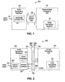
- FIG. 1 shows a block diagram of an audio recognition peripheral system 100 according to one embodiment of the present invention.
- Audio recognition peripheral system 100 includes a programmable processing unit 110 on a first integrated circuit coupled to an audio recognition peripheral 120 on a second integrated circuit through a bus 130 .
- the bus 130 may be any bus included on the particular programmable processing unit 110 chosen by the system designer.
- An audio signal 125 is input to the recognition peripheral 120 and received by a feature extractor 122 residing on the recognition peripheral 120 .
- the audio recognition peripheral system 100 of FIG. 1 is highly advantageous to system designers because it allows system designers to add audio recognition functionality into any system having a general purpose programmable processor, such as a microprocessor or microcontroller, without severely loading down the processor's resources and without drastically increasing the final system cost or design time cost.
- the functionality and/or features of a particular product may be implemented by a general purpose programmable processor, and audio recognition functionality partitioned between the processor and the audio recognition peripheral.
- a microprocessor may implement some or all of the functional (i.e. operational) flow for a particular product.
- the microprocessor controls the flow of how the features and/or functions of the product are implemented.
- the designer of the product can add audio recognition functionality simply by coupling the microprocessor to the audio recognition peripheral over the microprocessor's bus, and then accessing and/or executing an audio recognition algorithm as required during execution of the products functional flow to incorporate audio recognition.
- audio recognition peripheral system 100 loads an audio recognition algorithm 101 into the programmable processing unit 110 from an external memory (not shown).
- the programmable processing unit 110 also transmits control signals and interface information to the audio recognition peripheral 120 over the general purpose bus 130 .
- the general purpose bus 130 may comprise control, address, and data information.
- the bus 130 may include either distinct control, address, and data lines or parallel lines carrying the combination of control/address/data. Additionally, the bus 130 may be comprised of partitioned combinations thereof such as distinct control lines and combined address/data lines. Of course, a serial bus may also be employed.
- the control signals and interface information are received by the audio recognition peripheral 120 , and in accordance therewith, the feature extractor 122 can be configured to extract audio recognition features from the audio signal 125 .
- the audio signal 125 is input to the feature extractor 122 on the audio recognition peripheral 120 .
- the feature extractor 122 receives the audio signal 125 and extracts audio recognition features to produce feature extraction data.
- the feature extraction data is transmitted over the general purpose bus 130 from the audio recognition peripheral 120 to the programmable processing unit 110 for use in the audio recognition algorithm 101 .
- the audio recognition algorithm is executed on the feature extraction data.
- the feature extraction portion of the audio recognition operation is removed from the programmable processing unit 110 and implemented on the audio recognition peripheral 120 , thereby drastically reducing the resource loading on the programmable processing unit 110 .
- the present invention allows system designers to add audio recognition functionality to their systems simply by adding a low cost audio recognition peripheral integrated circuit to run alongside the processing unit.
- the need for application specific integrated circuits that incorporate a dedicated microprocessor for performing the audio recognition functions is eliminated.
- FIG. 2 shows a block diagram of an audio recognition peripheral system 200 according to another embodiment of the present invention.
- Audio recognition peripheral system 200 includes a central processing unit (CPU) 210 on a first integrated circuit coupled to an audio recognition peripheral 220 on a second integrated circuit through a bus 230 .
- the bus 230 of FIG. 2 comprises an address bus 231 , a data bus 232 , and control lines 233 .
- An audio signal 225 is input to the recognition peripheral integrated circuit 220 and received by a feature extractor 222 residing on the recognition peripheral 220 .
- the recognition peripheral 220 also includes an interface controller 221 and a vector processor 223 coupled to the bus 230 .
- the CPU 210 transmits control signals and interface information to the audio recognition peripheral 220 over the bus 230 .
- the control signal and interface information are received at the interface controller 221 .
- the interface controller 221 operates in response the control signals on the control lines 233 and the interface information on the address and data buses 231 and 232 .
- the interface controller 221 may be a state machine or programmable logic array which receives the control signals, address, and data information from the CPU 210 indicating that a feature extractor configuration operation is to occur.
- the interface controller 221 then generates peripheral configuration signals for configuring the feature extractor in accordance with the particular address and data information that was transmitted by the CPU 210 .
- Interface information typically may include address and/or data information for accessing control registers residing on the recognition peripheral and loading such registers with data as will be described in more detail below, for example.
- the CPU transmits control signals and interface information for configuring the feature extractor 222 to extract audio recognition features from the audio signal 225 . Thereafter, when the audio signal 225 is received by the feature extractor, audio recognition features are extracted to produce feature extraction data.
- the recognition peripheral then transmits the feature extraction data to the CPU, and the CPU executes the audio recognition algorithm 201 on the feature extraction data.
- the audio recognition peripheral 220 of FIG. 2 also includes a vector processor 223 coupled to the interface controller 221 and the central processing unit 210 .
- the CPU may send control signals and interface information on the bus 230 to the interface controller 221 indicating that the vector processor is to perform a vector operation.
- the audio recognition algorithm 201 is a template based recognition algorithm (e.g. a pattern matching algorithm)
- the CPU may send control signals, address, and data information on the bus 230 to program the vector processor to calculate the vector distance between two vectors as will be described in more detail below.
- the audio recognition algorithm 201 is a neural network based recognition algorithm.
- the CPU may send control signals, address, and data information on the bus 230 to program the vector processor to perform a multiply-accumulate operation on a plurality of pattern values and neural network weights as will also be described in more detail below. Therefore, in accordance with this embodiment of the present invention, the addition of a vector processor on the audio recognition peripheral 220 further reduces the loading on the CPU 210 during execution of an audio recognition algorithm 201 , and thereby improves the ability of a system designer to add highly effective audio recognition functionality simply by adding an audio recognition peripheral 210 to run alongside a processor.
- FIG. 3 shows an architectural diagram of an audio recognition peripheral 300 on a single integrated circuit according to one embodiment of the present invention.
- the audio recognition peripheral 300 includes a pre-amplifier 301 receiving an audio signal 325 .
- the output of the pre-amplifier 301 is coupled to an analog-to-digital converter 302 .
- the analog-to-digital converter 302 receives the pre-amplified audio signal and converts the signal to a digital audio signal.
- the digital audio signal is then transmitted to the input of a feature extractor 322 .
- the audio signal 325 can be received by the audio recognition peripheral 300 as a digital audio signal and input directly into the feature extractor.
- the feature extractor 322 receives the digital audio signal and extracts audio recognition features to produce feature extraction data.
- the feature extractor 322 is coupled to an external programmable processing unit (not shown) such as a microprocessor or microcontroller through an interface controller 321 .
- the interface controller 321 of the present embodiment is coupled to a bus 330 comprised of an address bus 331 , a data bus 332 , and a control bus 333 to allow the audio recognition peripheral 300 to be controlled by an external processing unit.
- a vector processor 323 and a memory 360 are coupled together and to the interface controller for communicating with an external processing unit.
- the interface controller 321 also includes configuration signal lines 350 for transmitting peripheral configuration signals between the interface controller 321 and the different elements included on the audio recognition peripheral 300 .
- the peripheral configuration signals on the configuration signal lines 350 may include information from the external processing unit for configuring and/or controlling the pre-amplifier, the digital-to-analog converter, the feature extractor, or the vector processor.
- an external processor may configure the audio recognition peripheral 320 by transmitting control, address, and data signals on the bus 330 .
- the interface controller 321 may receive the signals on the bus 330 and generate corresponding peripheral configuration signals on the configuration signal lines to configure the pre-amplifier, the digital-to-analog converter, or the feature extractor.
- an external processor may send control, address, and data information on the bus 330 to signal the audio recognition peripheral 300 to transmit the feature extraction data back to the external processor.
- the interface controller 321 may receive the transmitted signals from the external processor and generate corresponding peripheral configuration signals on the configuration signal lines 350 to cause the feature extractor to transmit the feature extraction data to the data bus over feature extractor output lines 340 .
- an audio recognition algorithm is run on the feature extraction data.
- the external processor may send control, address, and data information over the bus to configure the vector processor to perform a vector operation in accordance with the particular audio recognition algorithm being executed.
- the external processor transmits a first input of the vector processor over the bus 330 and directly into the memory 360 on memory input lines 342 .
- the external processor may then configure the vector processor to access the first input directly from the memory 360 into the vector processor using memory interface lines 344 .
- the vector processor may also be configured to access a second input stored in an external memory (not shown) using vector processor interface lines 346 .
- the vector processor may signal the external processor to enter a hold state while the vector processor takes control of the bus 330 to access the second input in the external memory.
- the vector processor will then perform the vector operation by accessing the first input on memory input lines 344 and the second input on vector processor interface lines 346 .
- the vector processor may signal the external processor to exit the hold state and transmit a result back to the external processor for use in the audio recognition algorithm.
- both the first and second inputs to the vector processor are loaded into memory 360 on memory input lines 342 .
- the external processor configures the vector processor 323 to access both the first input and second input directly from memory 360 over memory interface lines 344 . Accordingly, when the vector processor performs a vector operation on the first and second inputs, there is no need to access an external memory. Therefore, in this case the vector processor does not signal the external processor to enter a hold state.
- This technique has the advantage of allowing the external processor to maintain control of the bus during a vector operation, which allows the external processor to carry out other operations as may be required.
- the external processor executes a template based, or pattern matching, audio recognition algorithm.
- the input vectors to the vector processor are vector representations of audio signals also referred to as pattern vectors, which are based on the audio recognition features extracted by the feature extractor.
- the vector operation carried out by the vector processor may be a vector distance calculation.
- the external processor executes a neural network based audio recognition algorithm.
- one of the input vectors to the vector processor is a vector representation of an audio signal, or pattern vector, based on the audio recognition features
- the other input to the vector processor is a neural network.
- different types of audio recognition algorithms executing on the processor may call for variations in the feature extractor, the vector processor inputs, and the vector operation. Nevertheless, the features and advantages of executing an audio recognition algorithm on a processor coupled to a audio recognition peripheral according to the present invention are intended to cover such variations.
- FIG. 4 shows an example of an audio recognition peripheral integrated circuit 400 according to another embodiment of the present invention.
- Audio recognition peripheral 400 includes a pre-amplifier 401 , an analog-to-digital converter 402 , a feature extractor 422 , an interface controller 421 , a vector processor 423 , and a memory 460 .
- the pre-amplifier 401 receives an audio signal 425 , which may be a speech signal as shown in FIG. 4 .
- a speech signal is input to the audio recognition peripheral 400 and the audio recognition peripheral system, which includes the peripheral 400 and an external programmable processing unit (not shown), performs speech recognition.
- pre-amplifier 401 amplifies the audio signal 425 , the signal is converted into a digital audio signal in analog-to-digital converter 402 .
- a digital representation of the speech input signal is transferred from the analog-to-digital converter 425 to a feature extractor 422 on digital lines 403 .
- a system clock 495 is also included in audio recognition peripheral 400 , and may be either internally or externally generated. The clock may further be divided by divider 496 prior to clocking analog-to-digital converter 402 .
- the feature extractor 422 receives the digital signal and extracts audio recognition features from the digital audio signal to produce feature extraction data.
- feature extractor 422 receives the digital audio signal in a feature extractor filter unit 478 .
- the feature extractor filter unit 478 is an arithmetic logic unit (ALU) for receiving the digital input and calculating a plurality of filtered outputs.
- ALU arithmetic logic unit
- the present embodiment of feature extractor 422 also includes a filter controller 471 , a block generator 480 , a control memory 475 , and an intermediate storage memory 476 .
- the external processor configures the feature extractor by transmitting control signals and interface information on a bus to the interface controller.
- the interface controller 421 is coupled to an address bus 431 , data bus 432 , and control bus 433 .
- interface information including filter coefficients and control information is received and decoded by the interface controller and transmitted to the feature extractor by peripheral configuration signals on configuration signal lines 450 .
- the filter coefficients and a portion of the control information are stored in the control memory 475 .
- a portion of the control information is further loaded into filter control registers 472 in the filter controller 471 .
- the filter controller 471 also includes address generators 473 and 474 to allow the filter controller to access the control memory 475 and intermediate storage memory 476 .
- the digital audio signal is filtered in the ALU under the control of the filter controller 471 .
- a stream of sampled data is received from the analog-to-digital converter 402 in the feature extractor filter 478 at a rate of 18.6 KHz.
- the stream of sampled data is applied to six different digital filters implemented in the feature extractor filter 478 to produce six different filtered digital waveform streams also at a rate of 18.6 KHz.
- the six filtered waveforms are then transmitted to the block generator 480 from the filter result registers 479 .
- Block generator 480 receives the six filtered waveforms and performs a running calculation of average power and zero crossings.
- the results are loaded into block registers 481 as feature data blocks, and a block interrupt signal 482 is transmitted to the external processor to indicate that a feature data block is ready to be transmitted by the audio recognition peripheral.
- the external processor transmits control signals and interface information to read the feature data blocks from the block registers 481 over feature extractor output lines 440 .
- the average power and zero crossings are the parameters that comprise the audio recognition features for this particular embodiment. These parameters are used by the audio recognition algorithm running on the external processor to characterize the audio signal 425 . Moreover, the power values and zero crossing values generated by the feature extractor 422 in response to the audio signal 425 comprise the feature extraction data for the present embodiment.
- the particular parameters used for audio recognition features will depend on the particular audio recognition algorithm that is executed on the external processor. For the present embodiment, the audio recognition algorithm that is executed on the external processor operates in accordance with audio recognition features of average power and zero crossings. Additionally, for a particular algorithm the feature extraction data will comprise values corresponding to the parameters for a particular input signal. The feature extraction data is then applied as an input to the audio recognition algorithm on the external processor.
- One embodiment of the audio recognition peripheral 400 of FIG. 4 may also includes a vector processor 423 and/or memory 460 .
- the vector processor is designed to calculate the vector distance between two vectors, and is referred to as an “L1 Unit.”
- the memory of the present embodiment is a 2K SRAM.
- an audio recognition algorithm loaded on the external processor is executed on the feature extraction data.
- the audio recognition algorithm is a template matching algorithm.
- the external processor transmits control signals and interface information to the audio recognition peripheral indicating that a vector operation is to occur in the vector processor.
- the external processor loads a vector representation of the audio signal 425 into the memory 460 .
- the external processor sends control signals and interface information to configure the vector processor's configuration registers and address generators 427 to access the vector in memory 460 at one of the vector processor's inputs.
- the vector processor's configuration registers and address generators 427 are also programmed to access a second vector representing a template that is stored in an external memory (not shown) at a second vector processor input.
- the vector processor After the external processor has configured the vector processor 423 to access the required input data, the vector processor generates a CPU HOLD signal on control line 428 . This signals the external processor that the vector processor is ready to take control of the bus in order to carry out the vector operation.
- the external processor transmits a CPU ACK signal acknowledging that the external processor is ready to give up control of the bus during the vector operation.
- the vector processor accesses the vector stored in memory 460 over memory input lines 444 .
- the vector processor also accesses the template vector in external memory over vector processor interface lines 446 , which are coupled to the address bus 431 and data bus 432 through the interface controller 421 . It is important to note, however, that in some embodiments the address bus 431 and/or data bus 432 may flow through the interface controller directly to the vector processor 423 and/or memory 460 . This would allow either the vector processor 423 and/or the memory 460 to receive and/or transmit on the address bus and/or data bus directly, controlled by the control signals received at the interface controller 421 .
- the vector processor accesses the vector representation of the audio signal 425 in memory 460 beginning at the memory location previously programmed into one of the address generators 427 . It also accesses the template vector in external memory beginning at the memory location programmed into another one of the address generators 427 . Thereafter, the vector processor 423 calculates the vector distance between the two vectors. Once the vector processor has completed the vector distance calculation, it deactivates the CPU HOLD control line, thereby signaling the external processor that the operation is complete and that the bus is now available. The external processor then sends control signals and interface information to the interface controller 421 to access the registers in the vector processor to read out the result of the vector operation.
- the external processor loads both a first vector representation of the audio signal 425 and a second vector representing a template into the memory 460 .
- the memory 460 may be an 4K SRAM, for example.
- the external processor then sends control signals and interface information to configure the vector processor's configuration registers and address generators 427 to access the first vector in memory 460 at a first vector processor input and the second vector in memory 460 at a second vector processor input.
- the vector processor does not generate a CPU HOLD signal on control line 428 to carry out the vector operation because both vector inputs are accessed from peripheral memory 460 . Rather, the external processor maintains control of the bus while the vector operation is performed. This embodiment is advantageous because external processor is allowed to access the bus to perform other functions during a vector operation.
- the present invention is not limited to the above embodiment utilizing the vector processor for carrying out a distance calculation between two vectors.
- the vector operation executed by a vector processor may include, for example, loading pattern values and neural network weights into the memory 460 .
- the vector operation in that case would be to perform a multiply-accumulate operation on the pattern values and neural network weights as is well known by those skilled in the art.
- embodiments of the present invention have the advantage of allowing the system designer to offload burdensome vector processing operations associated with audio recognition from the programmable processing unit to the audio recognition peripheral during the execution of the audio recognition algorithm.
- the audio recognition peripheral 400 is coupled to an external processor (not shown) through interface controller 421 .
- Interface controller 421 is coupled to an address bus 431 and a data bus 432 for receiving interface information from the external processor.
- the audio recognition system 400 of the embodiment of FIG. 4 includes a control bus comprised of control signal lines 433 coupled to the interface controller 421 and to the vector processor 427 .
- the interface controller is operable in response to the control signals and interface information received from the external processor.
- the interface controller is coupled to the external processor using an address bus and data bus that are already included as part of the particular external processor selected by the system designer.
- the audio recognition peripheral includes an interface controller specifically designed to interface with the bus of a particular microprocessor or microcontroller. Therefore, the audio recognition peripheral 400 may simply be coupled to a standard control, address bus, and data bus of a particular microprocessor or microcontroller thereby easily adding efficient low cost audio recognition functionality.
- FIG. 5 illustrates decode logic 510 utilized in an interface controller 500 .
- Decode logic 510 receives control signals on control signal lines 533 and interface information on address bus 531 and data bus 532 , all from an external processor (not shown). These inputs from the external processor are received and evaluated by the decode logic 510 to generate configuration signals on configuration signal lines 550 .
- the configuration signals are used to communicate the control signals and interface information from the external processor to different resources in the audio recognition peripheral, such as the feature extractor or vector processor.
- the decode logic may be a state machine that produces a specific output in response to a given input as provided by the external processor, for example.
- the decode logic is implemented using a programmable logic array (PLA).
- Decode logic 510 also may pass through the address bus and data bus as shown at 560 and 570 . This is because some portions of the audio peripheral system may need to directly transmit or receive information to or from the address or data bus during certain operations, such as when the vector processor accesses an external memory directly, for example.
- control signaling according to one embodiment is illustrated.
- the external processor may access and/or configure different resources of the audio recognition peripheral 400 by transmitting control information to the decode logic 510 on the control signal lines 533 .
- Table 1 illustrates which resource is accessed in response to different control signals on the Select A line 552 and Select B line 551 .
- the decode logic 550 produce an output that prevents the audio recognition peripheral resources from accessing the address and/or data buses so the external processor can access another system residing on the bus.
- table 1 and the particular choice of control signals are illustrative only, and other variations or modifications could be implemented.
- one exemplary operation occurring under the control of the external processor is a feature extraction configuration operation.
- the external processor To configure the feature extractor 422 for an audio recognition operation, the external processor must load the feature extractor with the necessary control information. This is done by accessing filter control registers 472 inside the feature extractor and loading them with the necessary data.
- the external processor accesses the filter control registers by first sending control signals on the control signal lines Select A and Select B. As mentioned above, the Select A and Select B signal lines of audio recognition peripheral 400 are used to indicate to the interface controller 422 which portion of the peripheral is to be accessed by the external processor.
- the external processor then places the address of one of the feature extraction registers on the address bus, and places the corresponding data to be programmed into the register on the data bus. Additionally, the external processor will transmit a control signal on the CPU WR control signal line to indicate that the operation to be performed on the particular register is a write operation.
- the interface controller 421 decodes the signals Select A, Select B, CPU WR, and address on the address bus 431 to produce peripheral configuration signals on configuration signal line 450 for programming a register in the feature extractor with data on the data bus 432 .
- the interface controller 421 can be used to interface the audio recognition peripheral 400 with an external processor to access other registers in the pre-amplifier, the analog-to-digital converter, or the vector processor for configuring the system to perform an audio recognition operation.
- the external processor can also signal the interface controller to transmit feature extraction data from the feature extractor to the external processor as an input to the audio recognition algorithm running on the external processor.
- the external processor can place the address of each of the block registers 480 on the address bus.
- the external processor transmits a signal on the CPU RD control signal line.
- the external processor may configure the vector processor to perform a vector operation.
- the external processor places the address of one of vector processor configuration registers 427 on the address bus 431 and configuration data to be programmed into the register on the data bus 432 .
- the external processor transmits a signal on the CPU WR control signal line.
- the memory 460 is loaded with data directly by the external processor.
- the external processor places the address information on the address bus 431 and data to be programmed into the memory on the data bus 432 .
- the external processor accesses an external memory (not shown).
- the external processor places the address information on the address bus 431 and data to be programmed into the external memory on the data bus 432 .
- the external processor may access other memory on the bus.
- it is to be understood that other additional resources on the bus may be accessed by the external processor.
- the audio recognition peripheral optionally includes resources for synthesizing audio signals, as well as for recognition.
- the synthesis technique of the present embodiment allows for the addition of synthesis functionality using the same resources as provided for audio recognition. Therefore, as shown below, a system designer can obtain both audio recognition and audio synthesis at a very low cost and with a drastic reduction on processor loading by utilizing an audio recognition peripheral.
- the audio recognition peripheral 400 can be configured into a synthesis mode.
- the external processor transmits control signals and interface information to configure the feature extractor 422 for a synthesis operation.
- the control signals and interface information include filter coefficients and control information for the feature extractor.
- an excitation function is transmitted to the input of the feature extractor.
- the excitation function is transmitted from an external processor to the interface controller of the audio recognition peripheral over a bus.
- the interface controller then transmits the excitation function to the input of the feature extractor over synthesis excitation lines 457 .
- the synthesis excitation lines 457 are coupled to digital lines 403 at the input of the feature extractor 422 .
- the coefficients for the filter are downloaded from the control memory 475 into the feature extractor filter unit 478 to operate on the excitation function.
- the filter coefficients are programmed according to a linear predictive coding (“LPC”) technique to generate an audio output in response to the excitation function provided at the filter input.
- LPC linear predictive coding
- the feature extractor may also include a synthesis interrupt signal 491 to signal the external processor that synthesis mode filter results are ready to be transmitted.
- the filtered excitation signal may be output directly to the interface controller for transmission to the external processor on signal lines 483 , which interface with feature extractor output lines 440 .
- the filtered excitation signal is then transmitted back to the external processor for additional operations.
- a digital representation of an audio waveform is transmitted from the external processor back to the audio recognition peripheral.
- embodiments of the present invention may include a synthesis block 490 coupled to the interface controller 421 for receiving the digital representation of an audio waveform.
- the synthesis block is a pulse width modulation audio generator.
- other techniques for receiving an digital waveform and generating an audio output may include pulse code modulation, or sigma-delta conversion, for example.
- an audio recognition peripheral is used to implement record and playback functions.
- an audio signal e.g. a speech signal
- the audio signal is then processed by the feature extractor filter unit and transmitted directly over signal lines 483 to the interface controller and external processor.
- the recorded audio data may then be compressed by the external processor and stored in some form of memory such as a flash memory on the external processor or in an internal or external SRAM or DRAM. Later, the audio signal may be decompressed by the external processor and transmitted back to the audio recognition peripheral for playback through a synthesizer.
Landscapes
- Engineering & Computer Science (AREA)
- Computational Linguistics (AREA)
- Health & Medical Sciences (AREA)
- Audiology, Speech & Language Pathology (AREA)
- Human Computer Interaction (AREA)
- Physics & Mathematics (AREA)
- Acoustics & Sound (AREA)
- Multimedia (AREA)
- Advance Control (AREA)
Abstract
The present invention includes a novel audio recognition peripheral system and method. The audio recognition peripheral system comprises an audio recognition peripheral a programmable processor such as a microprocessor or microcontroller. In one embodiment, the audio recognition peripheral includes a feature extractor and vector processor. The feature extractor receives an audio signal and extracts recognition features. The extracted audio recognition features are transmitted to the programmable processor and processed in accordance with an audio recognition algorithm. During execution of the audio recognition algorithm, the programmable processor signals the audio recognition peripheral to perform vector operations. Thus, computationally intensive recognition operations are advantageously offloaded to the peripheral.
Description
The field of the present invention is integrated circuits for implementing audio recognition. More particularly, the present invention includes an apparatus and method of providing an audio recognition peripheral system allowing for a highly efficient implementation of an audio recognition process.
Audio recognition systems are widely used for providing computers and other electronic systems with the ability to receive audio input signals and perform operations in response to the particular characteristics of the audio input signal. One common application of audio recognition is speech recognition, for example. Using a speech recognition system, a computer or other electronic system may receive an audio input signal corresponding to speech and respond to the input signal in accordance with the specific speech that was received. For example, a user may provide spoken commands to a computer and using a speech recognition algorithm the computer may execute different functions in response different commands.
However, audio recognition systems are problematic to realize because they typically require large amounts of data processing to implement. For example, in one prior art implementation, an audio signal is digitized and provided as an input to a microprocessor. The microprocessor performs the speech recognition using software algorithms that operate on the digitized audio signal. This approach has the disadvantage of consuming large amounts resources and/or processor time in the microprocessor, thereby slowing down the performance of the overall system.
In another prior art implementation of an audio recognition system, an application specific audio recognition integrated circuit is used that incorporates a dedicated microprocessor with special hardware and software for performing the audio recognition operations. However, application specific audio recognition systems have the disadvantage of increasing the costs of the overall system. Moreover, application specific audio recognition systems are difficult to integrate into larger systems because of compatibility issues between the operating characteristics of the different devices in the system. Additionally, an application specific audio recognition integrated circuit will often be integrated into an electronic system controlled by a main processor. However, as the applications on the main processor are modified, additional modifications and adaptations on the application specific audio recognition integrated circuit may be required to conform to software changes in the main processor. Such modifications can be difficult, costly, and time consuming, and can make the overall electronic system costly and inflexible. Finally, application specific audio recognition systems typically have their own programming environments that users must learn in order to implement audio recognition functionality. Therefore, design cycles are increased in the development of new systems with a corresponding increase in cost.
Therefore, what is needed is an audio recognition system that allows users to efficiently implement audio recognition functionality into larger systems at reduced costs with both ease and flexibility of use.
Embodiments of the present invention solve the problems described above with respect to previously known systems and methods for implementing audio recognition. Specifically, the present invention provides an audio recognition peripheral and audio recognition peripheral system. The present invention allows system designers to easily add audio recognition functionality into a system by simply adding a low cost audio recognition peripheral to operate in conjunction with a processor.
In one embodiment the present invention includes an audio recognition peripheral system comprising a first integrated circuit having a programmable processing unit, the programmable processing unit loading an audio recognition algorithm to perform an audio recognition operation, and a second integrated circuit having a feature extractor coupled to the first integrated circuit, the second integrated circuit receiving an audio signal and extracting audio recognition features from the audio signal to produce feature extraction data, wherein the programmable processing unit receives the feature extraction data and executes the audio recognition algorithm on the feature extraction data.
In another embodiment, the second integrated circuit of the audio recognition peripheral system includes an interface controller coupled to the feature extractor and to the first integrated circuit, the interface controller operating in response to control signals received from the first integrated circuit.
In another embodiment, the second integrated circuit of the audio recognition peripheral system includes a vector processor coupled to the first integrated circuit, wherein interface information is received by the interface controller and includes information for configuring the vector processor to perform a specified operation during execution of the audio recognition algorithm by the programmable processing unit.
In one embodiment, the present invention includes an audio recognition peripheral on a single integrated circuit comprising a feature extractor, having an audio input for receiving an audio signal, the feature extractor extracting audio recognition features from the audio signal to produce feature extraction data, and an interface controller coupled to the feature extractor, the interface controller having an interface input for receiving external control signals and interface information, wherein the control signals and interface information configure the feature extractor to operate in accordance with an external audio recognition algorithm.
In another embodiment, when the audio recognition peripheral is in an extraction mode a filter unit receives an audio signal to generate feature extraction data, and when the audio recognition peripheral is in a synthesis mode the filter unit receives an excitation signal to generate audio information.
In another embodiment, the audio recognition peripheral further comprises a synthesizer for receiving digital audio information and producing an external analog audio output signal.
In another embodiment, the audio recognition peripheral further comprises a vector processor coupled to the interface controller. In yet another embodiment, the audio recognition peripheral further comprises a memory coupled to the vector processor.
In one embodiment, the present invention includes an audio recognition method comprising loading an audio recognition algorithm in a first integrated circuit, the first integrated circuit having a programmable processing unit, transmitting control signals and interface information from the first integrated circuit to a second integrated circuit having a feature extractor, and in accordance therewith, configuring the second integrated circuit to extract audio recognition features, receiving an audio signal in the feature extractor of the second integrated circuit, extracting audio recognition features from the audio signal to produce feature extraction data, transmitting the feature extraction data from the second integrated circuit to the first integrated circuit, and executing the audio recognition algorithm on the feature extraction data in the first integrated circuit.
In one embodiment, the present invention includes a method of processing an audio signal on a single integrated circuit for audio recognition comprising receiving external control signals and interface information in a interface controller corresponding to the external execution of an audio recognition algorithm, and in accordance therewith, configuring a feature extractor, receiving the audio signal in the feature extractor, extracting audio recognition features from the audio signal to produce feature extraction data, and transmitting the feature extraction data external to the integrated circuit.
These and other embodiments of the present invention, as well as its advantages and features, are describe in more detail in conjunction with the text below and attached figures.
FIG. 1 illustrates a block diagram of an audio recognition peripheral system according to one embodiment of the present invention.
FIG. 2 illustrates an example of an audio recognition peripheral system utilizing an interface controller and vector processor coupled to a central processing unit via a control bus, an address bus, and a data bus according to another embodiment of the present invention.
FIG. 3 illustrates an architectural diagram of an audio recognition peripheral on a single integrated circuit according to one embodiment of the present invention.
FIG. 4 illustrates an example of an audio recognition peripheral according to another embodiment of the present invention.
FIG. 5 illustrates decode logic utilized in an interface controller according to one embodiment of the present invention.
FIG. 1 shows a block diagram of an audio recognition peripheral system 100 according to one embodiment of the present invention. Audio recognition peripheral system 100 includes a programmable processing unit 110 on a first integrated circuit coupled to an audio recognition peripheral 120 on a second integrated circuit through a bus 130. The bus 130 may be any bus included on the particular programmable processing unit 110 chosen by the system designer. An audio signal 125 is input to the recognition peripheral 120 and received by a feature extractor 122 residing on the recognition peripheral 120.
The audio recognition peripheral system 100 of FIG. 1 is highly advantageous to system designers because it allows system designers to add audio recognition functionality into any system having a general purpose programmable processor, such as a microprocessor or microcontroller, without severely loading down the processor's resources and without drastically increasing the final system cost or design time cost. Accordingly, in one embodiment, the functionality and/or features of a particular product may be implemented by a general purpose programmable processor, and audio recognition functionality partitioned between the processor and the audio recognition peripheral. For example, a microprocessor may implement some or all of the functional (i.e. operational) flow for a particular product. In other words, the microprocessor controls the flow of how the features and/or functions of the product are implemented. The designer of the product can add audio recognition functionality simply by coupling the microprocessor to the audio recognition peripheral over the microprocessor's bus, and then accessing and/or executing an audio recognition algorithm as required during execution of the products functional flow to incorporate audio recognition.
To execute an audio recognition operation, audio recognition peripheral system 100 loads an audio recognition algorithm 101 into the programmable processing unit 110 from an external memory (not shown). As part of an audio recognition operation, the programmable processing unit 110 also transmits control signals and interface information to the audio recognition peripheral 120 over the general purpose bus 130. The general purpose bus 130 may comprise control, address, and data information. The bus 130 may include either distinct control, address, and data lines or parallel lines carrying the combination of control/address/data. Additionally, the bus 130 may be comprised of partitioned combinations thereof such as distinct control lines and combined address/data lines. Of course, a serial bus may also be employed. The control signals and interface information are received by the audio recognition peripheral 120, and in accordance therewith, the feature extractor 122 can be configured to extract audio recognition features from the audio signal 125.
During execution of an audio recognition operation, the audio signal 125 is input to the feature extractor 122 on the audio recognition peripheral 120. The feature extractor 122 receives the audio signal 125 and extracts audio recognition features to produce feature extraction data. The feature extraction data is transmitted over the general purpose bus 130 from the audio recognition peripheral 120 to the programmable processing unit 110 for use in the audio recognition algorithm 101. Once the feature extraction data has been received by the processing unit 110, the audio recognition algorithm is executed on the feature extraction data.
Therefore, in accordance with one embodiment of the present invention, the feature extraction portion of the audio recognition operation is removed from the programmable processing unit 110 and implemented on the audio recognition peripheral 120, thereby drastically reducing the resource loading on the programmable processing unit 110. Moreover, by coupling the audio recognition peripheral 120 to a programmable processing unit 110 through a bus 130 included on the particular processing unit chosen by the system designer, the present invention allows system designers to add audio recognition functionality to their systems simply by adding a low cost audio recognition peripheral integrated circuit to run alongside the processing unit. Finally, by loading and executing the audio recognition algorithm on a programmable processing unit 110, the need for application specific integrated circuits that incorporate a dedicated microprocessor for performing the audio recognition functions is eliminated.
FIG. 2 shows a block diagram of an audio recognition peripheral system 200 according to another embodiment of the present invention. Audio recognition peripheral system 200 includes a central processing unit (CPU) 210 on a first integrated circuit coupled to an audio recognition peripheral 220 on a second integrated circuit through a bus 230. The bus 230 of FIG. 2 comprises an address bus 231, a data bus 232, and control lines 233. An audio signal 225 is input to the recognition peripheral integrated circuit 220 and received by a feature extractor 222 residing on the recognition peripheral 220. In the embodiment of FIG. 2, the recognition peripheral 220 also includes an interface controller 221 and a vector processor 223 coupled to the bus 230.
To execute an audio recognition operation, the CPU 210 transmits control signals and interface information to the audio recognition peripheral 220 over the bus 230. The control signal and interface information are received at the interface controller 221. The interface controller 221 operates in response the control signals on the control lines 233 and the interface information on the address and data buses 231 and 232. For example, the interface controller 221 may be a state machine or programmable logic array which receives the control signals, address, and data information from the CPU 210 indicating that a feature extractor configuration operation is to occur. The interface controller 221 then generates peripheral configuration signals for configuring the feature extractor in accordance with the particular address and data information that was transmitted by the CPU 210. The control signals input to the interface controller allow the CPU to control the types of operations that are executed by the recognition peripheral. Interface information typically may include address and/or data information for accessing control registers residing on the recognition peripheral and loading such registers with data as will be described in more detail below, for example.
At the beginning of an audio recognition operation, the CPU transmits control signals and interface information for configuring the feature extractor 222 to extract audio recognition features from the audio signal 225. Thereafter, when the audio signal 225 is received by the feature extractor, audio recognition features are extracted to produce feature extraction data. The recognition peripheral then transmits the feature extraction data to the CPU, and the CPU executes the audio recognition algorithm 201 on the feature extraction data.
The audio recognition peripheral 220 of FIG. 2 also includes a vector processor 223 coupled to the interface controller 221 and the central processing unit 210. During execution of the audio recognition algorithm 201 on the feature extraction data, the CPU may send control signals and interface information on the bus 230 to the interface controller 221 indicating that the vector processor is to perform a vector operation. For example, if the audio recognition algorithm 201 is a template based recognition algorithm (e.g. a pattern matching algorithm), the CPU may send control signals, address, and data information on the bus 230 to program the vector processor to calculate the vector distance between two vectors as will be described in more detail below. In another embodiment, the audio recognition algorithm 201 is a neural network based recognition algorithm. In that embodiment the CPU may send control signals, address, and data information on the bus 230 to program the vector processor to perform a multiply-accumulate operation on a plurality of pattern values and neural network weights as will also be described in more detail below. Therefore, in accordance with this embodiment of the present invention, the addition of a vector processor on the audio recognition peripheral 220 further reduces the loading on the CPU 210 during execution of an audio recognition algorithm 201, and thereby improves the ability of a system designer to add highly effective audio recognition functionality simply by adding an audio recognition peripheral 210 to run alongside a processor.
FIG. 3 shows an architectural diagram of an audio recognition peripheral 300 on a single integrated circuit according to one embodiment of the present invention. The audio recognition peripheral 300 includes a pre-amplifier 301 receiving an audio signal 325. The output of the pre-amplifier 301 is coupled to an analog-to-digital converter 302. The analog-to-digital converter 302 receives the pre-amplified audio signal and converts the signal to a digital audio signal. The digital audio signal is then transmitted to the input of a feature extractor 322. Of course, in other embodiments the audio signal 325 can be received by the audio recognition peripheral 300 as a digital audio signal and input directly into the feature extractor. The feature extractor 322 receives the digital audio signal and extracts audio recognition features to produce feature extraction data. The feature extractor 322 is coupled to an external programmable processing unit (not shown) such as a microprocessor or microcontroller through an interface controller 321. The interface controller 321 of the present embodiment is coupled to a bus 330 comprised of an address bus 331, a data bus 332, and a control bus 333 to allow the audio recognition peripheral 300 to be controlled by an external processing unit. Also included on the audio recognition peripheral 300 of the present embodiment is a vector processor 323 and a memory 360 that are coupled together and to the interface controller for communicating with an external processing unit.
The interface controller 321 also includes configuration signal lines 350 for transmitting peripheral configuration signals between the interface controller 321 and the different elements included on the audio recognition peripheral 300. The peripheral configuration signals on the configuration signal lines 350 may include information from the external processing unit for configuring and/or controlling the pre-amplifier, the digital-to-analog converter, the feature extractor, or the vector processor. For example, during an audio recognition operation, an external processor may configure the audio recognition peripheral 320 by transmitting control, address, and data signals on the bus 330. The interface controller 321 may receive the signals on the bus 330 and generate corresponding peripheral configuration signals on the configuration signal lines to configure the pre-amplifier, the digital-to-analog converter, or the feature extractor. For another example, when the feature extractor is generating feature extraction data in response to an audio signal 325, an external processor may send control, address, and data information on the bus 330 to signal the audio recognition peripheral 300 to transmit the feature extraction data back to the external processor. The interface controller 321 may receive the transmitted signals from the external processor and generate corresponding peripheral configuration signals on the configuration signal lines 350 to cause the feature extractor to transmit the feature extraction data to the data bus over feature extractor output lines 340.
After the feature extraction data has been transmitted to the external processor, an audio recognition algorithm is run on the feature extraction data. As part of the audio recognition algorithm, the external processor may send control, address, and data information over the bus to configure the vector processor to perform a vector operation in accordance with the particular audio recognition algorithm being executed. In one embodiment, the external processor transmits a first input of the vector processor over the bus 330 and directly into the memory 360 on memory input lines 342. The external processor may then configure the vector processor to access the first input directly from the memory 360 into the vector processor using memory interface lines 344. The vector processor may also be configured to access a second input stored in an external memory (not shown) using vector processor interface lines 346. During a vector operation, the vector processor may signal the external processor to enter a hold state while the vector processor takes control of the bus 330 to access the second input in the external memory. The vector processor will then perform the vector operation by accessing the first input on memory input lines 344 and the second input on vector processor interface lines 346. After performing the vector operation, the vector processor may signal the external processor to exit the hold state and transmit a result back to the external processor for use in the audio recognition algorithm.
In another embodiment, both the first and second inputs to the vector processor are loaded into memory 360 on memory input lines 342. In this case, the external processor configures the vector processor 323 to access both the first input and second input directly from memory 360 over memory interface lines 344. Accordingly, when the vector processor performs a vector operation on the first and second inputs, there is no need to access an external memory. Therefore, in this case the vector processor does not signal the external processor to enter a hold state. This technique has the advantage of allowing the external processor to maintain control of the bus during a vector operation, which allows the external processor to carry out other operations as may be required.
It is important to point out that the inputs to the vector processor, as well as the specific vector operation performed by the vector processor, will vary depending upon the type of audio recognition algorithm running on the external processor. For example, in one embodiment, the external processor executes a template based, or pattern matching, audio recognition algorithm. In that case, the input vectors to the vector processor are vector representations of audio signals also referred to as pattern vectors, which are based on the audio recognition features extracted by the feature extractor. Additionally, the vector operation carried out by the vector processor may be a vector distance calculation. In another embodiment, the external processor executes a neural network based audio recognition algorithm. In that case, one of the input vectors to the vector processor is a vector representation of an audio signal, or pattern vector, based on the audio recognition features, and the other input to the vector processor is a neural network. However, is to be understood that different types of audio recognition algorithms executing on the processor may call for variations in the feature extractor, the vector processor inputs, and the vector operation. Nevertheless, the features and advantages of executing an audio recognition algorithm on a processor coupled to a audio recognition peripheral according to the present invention are intended to cover such variations.
FIG. 4 shows an example of an audio recognition peripheral integrated circuit 400 according to another embodiment of the present invention. Audio recognition peripheral 400 includes a pre-amplifier 401, an analog-to-digital converter 402, a feature extractor 422, an interface controller 421, a vector processor 423, and a memory 460. The pre-amplifier 401 receives an audio signal 425, which may be a speech signal as shown in FIG. 4. Accordingly, in one embodiment of the present invention a speech signal is input to the audio recognition peripheral 400 and the audio recognition peripheral system, which includes the peripheral 400 and an external programmable processing unit (not shown), performs speech recognition. After pre-amplifier 401 amplifies the audio signal 425, the signal is converted into a digital audio signal in analog-to-digital converter 402. A digital representation of the speech input signal is transferred from the analog-to-digital converter 425 to a feature extractor 422 on digital lines 403. A system clock 495 is also included in audio recognition peripheral 400, and may be either internally or externally generated. The clock may further be divided by divider 496 prior to clocking analog-to-digital converter 402. The feature extractor 422 receives the digital signal and extracts audio recognition features from the digital audio signal to produce feature extraction data.
For the embodiment of FIG. 4, feature extractor 422 receives the digital audio signal in a feature extractor filter unit 478. In one embodiment, the feature extractor filter unit 478 is an arithmetic logic unit (ALU) for receiving the digital input and calculating a plurality of filtered outputs. The present embodiment of feature extractor 422 also includes a filter controller 471, a block generator 480, a control memory 475, and an intermediate storage memory 476.
Prior to the execution of an audio recognition operation, the external processor configures the feature extractor by transmitting control signals and interface information on a bus to the interface controller. For the embodiment of FIG. 4, the interface controller 421 is coupled to an address bus 431, data bus 432, and control bus 433. To configure the feature extractor, interface information including filter coefficients and control information is received and decoded by the interface controller and transmitted to the feature extractor by peripheral configuration signals on configuration signal lines 450. The filter coefficients and a portion of the control information are stored in the control memory 475. Additionally, a portion of the control information is further loaded into filter control registers 472 in the filter controller 471. The filter controller 471 also includes address generators 473 and 474 to allow the filter controller to access the control memory 475 and intermediate storage memory 476.
During execution of an audio recognition operation, the digital audio signal is filtered in the ALU under the control of the filter controller 471. In one embodiment, a stream of sampled data is received from the analog-to-digital converter 402 in the feature extractor filter 478 at a rate of 18.6 KHz. The stream of sampled data is applied to six different digital filters implemented in the feature extractor filter 478 to produce six different filtered digital waveform streams also at a rate of 18.6 KHz. The six filtered waveforms are then transmitted to the block generator 480 from the filter result registers 479. Block generator 480 receives the six filtered waveforms and performs a running calculation of average power and zero crossings. When 250 outputs have been accumulated, the results are loaded into block registers 481 as feature data blocks, and a block interrupt signal 482 is transmitted to the external processor to indicate that a feature data block is ready to be transmitted by the audio recognition peripheral. In response to the block interrupt signal 482, the external processor transmits control signals and interface information to read the feature data blocks from the block registers 481 over feature extractor output lines 440.
It is important to note that the average power and zero crossings are the parameters that comprise the audio recognition features for this particular embodiment. These parameters are used by the audio recognition algorithm running on the external processor to characterize the audio signal 425. Moreover, the power values and zero crossing values generated by the feature extractor 422 in response to the audio signal 425 comprise the feature extraction data for the present embodiment. The particular parameters used for audio recognition features will depend on the particular audio recognition algorithm that is executed on the external processor. For the present embodiment, the audio recognition algorithm that is executed on the external processor operates in accordance with audio recognition features of average power and zero crossings. Additionally, for a particular algorithm the feature extraction data will comprise values corresponding to the parameters for a particular input signal. The feature extraction data is then applied as an input to the audio recognition algorithm on the external processor. It should be understood however that different techniques of feature extraction may be implemented on the audio recognition peripheral 400 without departing from the spirit and scope of the present invention. Accordingly, different feature extraction techniques may involve different audio recognition features and feature extraction data. Therefore, the feature extractor may require alternative implementations. However, the embodiments described herein are illustrative of the advantages of providing a recognition peripheral system on one integrated circuit, and executing an audio recognition algorithm on an external processor. Therefore, the above embodiment is to be understood as illustrative and not limiting.
One embodiment of the audio recognition peripheral 400 of FIG. 4 may also includes a vector processor 423 and/or memory 460. For audio recognition peripheral 400, the vector processor is designed to calculate the vector distance between two vectors, and is referred to as an “L1 Unit.” Additionally, the memory of the present embodiment is a 2K SRAM. During an audio recognition operation, an audio recognition algorithm loaded on the external processor is executed on the feature extraction data. In one embodiment, for example, the audio recognition algorithm is a template matching algorithm. During execution of the algorithm on the feature extraction data, the external processor transmits control signals and interface information to the audio recognition peripheral indicating that a vector operation is to occur in the vector processor. For the template matching algorithm, the external processor loads a vector representation of the audio signal 425 into the memory 460. Additionally, the external processor sends control signals and interface information to configure the vector processor's configuration registers and address generators 427 to access the vector in memory 460 at one of the vector processor's inputs. The vector processor's configuration registers and address generators 427 are also programmed to access a second vector representing a template that is stored in an external memory (not shown) at a second vector processor input. After the external processor has configured the vector processor 423 to access the required input data, the vector processor generates a CPU HOLD signal on control line 428. This signals the external processor that the vector processor is ready to take control of the bus in order to carry out the vector operation. In response to the CPU HOLD signal, the external processor transmits a CPU ACK signal acknowledging that the external processor is ready to give up control of the bus during the vector operation. The vector processor accesses the vector stored in memory 460 over memory input lines 444. The vector processor also accesses the template vector in external memory over vector processor interface lines 446, which are coupled to the address bus 431 and data bus 432 through the interface controller 421. It is important to note, however, that in some embodiments the address bus 431 and/or data bus 432 may flow through the interface controller directly to the vector processor 423 and/or memory 460. This would allow either the vector processor 423 and/or the memory 460 to receive and/or transmit on the address bus and/or data bus directly, controlled by the control signals received at the interface controller 421.
Once the vector processor has control of the bus, it accesses the vector representation of the audio signal 425 in memory 460 beginning at the memory location previously programmed into one of the address generators 427. It also accesses the template vector in external memory beginning at the memory location programmed into another one of the address generators 427. Thereafter, the vector processor 423 calculates the vector distance between the two vectors. Once the vector processor has completed the vector distance calculation, it deactivates the CPU HOLD control line, thereby signaling the external processor that the operation is complete and that the bus is now available. The external processor then sends control signals and interface information to the interface controller 421 to access the registers in the vector processor to read out the result of the vector operation.
In yet another embodiment, the external processor loads both a first vector representation of the audio signal 425 and a second vector representing a template into the memory 460. For this embodiment, the memory 460 may be an 4K SRAM, for example. The external processor then sends control signals and interface information to configure the vector processor's configuration registers and address generators 427 to access the first vector in memory 460 at a first vector processor input and the second vector in memory 460 at a second vector processor input. However, in this embodiment, the vector processor does not generate a CPU HOLD signal on control line 428 to carry out the vector operation because both vector inputs are accessed from peripheral memory 460. Rather, the external processor maintains control of the bus while the vector operation is performed. This embodiment is advantageous because external processor is allowed to access the bus to perform other functions during a vector operation.
It is important to note that the present invention is not limited to the above embodiment utilizing the vector processor for carrying out a distance calculation between two vectors. For example, if the audio recognition algorithm running on the external processor was a neural network recognition algorithm, the vector operation executed by a vector processor may include, for example, loading pattern values and neural network weights into the memory 460. The vector operation in that case would be to perform a multiply-accumulate operation on the pattern values and neural network weights as is well known by those skilled in the art. Accordingly, as further illustrated by the embodiment of FIG. 4, embodiments of the present invention have the advantage of allowing the system designer to offload burdensome vector processing operations associated with audio recognition from the programmable processing unit to the audio recognition peripheral during the execution of the audio recognition algorithm.
Referring again to FIG. 4, the audio recognition peripheral 400 is coupled to an external processor (not shown) through interface controller 421. Interface controller 421 is coupled to an address bus 431 and a data bus 432 for receiving interface information from the external processor. Additionally, the audio recognition system 400 of the embodiment of FIG. 4 includes a control bus comprised of control signal lines 433 coupled to the interface controller 421 and to the vector processor 427. The interface controller is operable in response to the control signals and interface information received from the external processor. In one embodiment of the present invention, the interface controller is coupled to the external processor using an address bus and data bus that are already included as part of the particular external processor selected by the system designer. In other words, the audio recognition peripheral includes an interface controller specifically designed to interface with the bus of a particular microprocessor or microcontroller. Therefore, the audio recognition peripheral 400 may simply be coupled to a standard control, address bus, and data bus of a particular microprocessor or microcontroller thereby easily adding efficient low cost audio recognition functionality.
Referring now to FIG. 5, the operability of interface controller 421 according to one embodiment of the present invention can be understood. FIG. 5 illustrates decode logic 510 utilized in an interface controller 500. Decode logic 510 receives control signals on control signal lines 533 and interface information on address bus 531 and data bus 532, all from an external processor (not shown). These inputs from the external processor are received and evaluated by the decode logic 510 to generate configuration signals on configuration signal lines 550. The configuration signals, in turn, are used to communicate the control signals and interface information from the external processor to different resources in the audio recognition peripheral, such as the feature extractor or vector processor. The decode logic may be a state machine that produces a specific output in response to a given input as provided by the external processor, for example. In one embodiment, the decode logic is implemented using a programmable logic array (PLA). Decode logic 510 also may pass through the address bus and data bus as shown at 560 and 570. This is because some portions of the audio peripheral system may need to directly transmit or receive information to or from the address or data bus during certain operations, such as when the vector processor accesses an external memory directly, for example.
Referring to FIGS. 4-5 and Table 1, control signaling according to one embodiment is illustrated. In this embodiment, the external processor may access and/or configure different resources of the audio recognition peripheral 400 by transmitting control information to the decode logic 510 on the control signal lines 533. For example, Table 1 below illustrates which resource is accessed in response to different control signals on the Select A line 552 and Select B line 551.
| TABLE 1 | ||||
| Select A | Select B | Peripheral Resource | ||
| 0 | 0 | External Resource | ||
| 0 | 1 | Memory (SRAM) | ||
| 1 | 0 | Feature Extractor | ||
| 1 | 1 | Vector Processor | ||
Therefore, with reference to Table 1, when the external processor transmits control signals Select A and Select B {A, B}={1, 0}, the decode logic 550 will produce an output on configuration signal lines 550 to communicate with the feature extractor 422. Additionally, when the external processor transmits {A, B}={1, 1}, the decode logic 550 will produce an output on configuration signal line 550 to communicate with the vector processor 423. Moreover, when the external processor transmits {A, B}={0, 1}, the decode logic 550 will produce an output on configuration signal line 550 to communicate with the memory 460. Finally, when the external processor transmits {A, B}={0, 0}, the decode logic 550 produce an output that prevents the audio recognition peripheral resources from accessing the address and/or data buses so the external processor can access another system residing on the bus. Of course, table 1 and the particular choice of control signals are illustrative only, and other variations or modifications could be implemented.
Referring again to FIG. 4, one exemplary operation occurring under the control of the external processor is a feature extraction configuration operation. To configure the feature extractor 422 for an audio recognition operation, the external processor must load the feature extractor with the necessary control information. This is done by accessing filter control registers 472 inside the feature extractor and loading them with the necessary data. The external processor accesses the filter control registers by first sending control signals on the control signal lines Select A and Select B. As mentioned above, the Select A and Select B signal lines of audio recognition peripheral 400 are used to indicate to the interface controller 422 which portion of the peripheral is to be accessed by the external processor. For example, an external processor transmission of {A, B}={1, 0} may indicate to the interface controller 421 that the external processor is going to configure one of the registers in the feature extractor. The external processor then places the address of one of the feature extraction registers on the address bus, and places the corresponding data to be programmed into the register on the data bus. Additionally, the external processor will transmit a control signal on the CPU WR control signal line to indicate that the operation to be performed on the particular register is a write operation. The interface controller receives the control signals {A, B}={1, 0} and will know that the address on the address bus corresponds to the address of a register in the feature extractor, rather than some other register residing in another portion of the audio recognition peripheral with the same address (i.e. a register in the vector processor with the same address for example). Therefore, the interface controller 421 decodes the signals Select A, Select B, CPU WR, and address on the address bus 431 to produce peripheral configuration signals on configuration signal line 450 for programming a register in the feature extractor with data on the data bus 432. According to the same technique, the interface controller 421 can be used to interface the audio recognition peripheral 400 with an external processor to access other registers in the pre-amplifier, the analog-to-digital converter, or the vector processor for configuring the system to perform an audio recognition operation.
As another example of the operation of the interface controller 421, the external processor can also signal the interface controller to transmit feature extraction data from the feature extractor to the external processor as an input to the audio recognition algorithm running on the external processor. In response to a block interrupt signal 482 from the feature extractor, the external processor transmits {A, B}={1, 0} control signals on control signal lines 551 and 552. Additionally, the external processor can place the address of each of the block registers 480 on the address bus. Finally, the external processor transmits a signal on the CPU RD control signal line. These signals are received by the decode logic 510 in the interface controller to produce a configuration signal on the configuration signal lines coupled to the feature extractor. As a result, each of the block registers 480 are accessed and the feature extraction data stored therein is transmitted onto the data bus 432 and into the external processor.
As previously disclosed, during execution of the audio recognition algorithm on the feature extracted data, the external processor may configure the vector processor to perform a vector operation. To perform a vector processor configuration operation, the external processor transmits {A, B}={1, 1} control signals on control signal lines 551 and 552. Additionally, the external processor places the address of one of vector processor configuration registers 427 on the address bus 431 and configuration data to be programmed into the register on the data bus 432. Finally, the external processor transmits a signal on the CPU WR control signal line. These signals are received by the decode logic 510 in the interface controller to produce an configuration signal on the configuration signal lines coupled to the vector processor. As a result, the vector processor configuration register 427 is accessed and the configuration data on the data bus is transmitted therein. The process is repeated for all registers in the vector processor as required for configuration.
In one embodiment of the present invention, the memory 460 is loaded with data directly by the external processor. To load the memory 460, the external processor transmits {A, B}={0, 1} control signals on control signal lines 551 and 552. Additionally, the external processor places the address information on the address bus 431 and data to be programmed into the memory on the data bus 432. These signals are received by the decode logic 510 and, in response to a memory access command {A, B}={0, 1}, the information on the address bus 431 and data bus 432 pass through the interface controller to the memory 460 for storage.
In another embodiment, the external processor accesses an external memory (not shown). To access an external memory, the external processor transmits {A, B}={0, 0} control signals on control signal lines 551 and 552. Additionally, the external processor places the address information on the address bus 431 and data to be programmed into the external memory on the data bus 432. These signals are received by the decode logic 510 and, in response to a external resource access command {A, B}={0, 0}, the decode logic will pass the CPU RD signal 554 and/or CPU WR signal 553 through the system on signal lines EXT RD 580 or EXT WR 590. As a result, the external processor may access other memory on the bus. Similarly, it is to be understood that other additional resources on the bus may be accessed by the external processor.
In yet another embodiment of the present invention, the audio recognition peripheral optionally includes resources for synthesizing audio signals, as well as for recognition. The synthesis technique of the present embodiment allows for the addition of synthesis functionality using the same resources as provided for audio recognition. Therefore, as shown below, a system designer can obtain both audio recognition and audio synthesis at a very low cost and with a drastic reduction on processor loading by utilizing an audio recognition peripheral.
Referring to FIG. 4, in one embodiment, the audio recognition peripheral 400 can be configured into a synthesis mode. To configure the peripheral into synthesis mode, the external processor transmits control signals and interface information to configure the feature extractor 422 for a synthesis operation. The control signals and interface information include filter coefficients and control information for the feature extractor. Then, an excitation function is transmitted to the input of the feature extractor. The excitation function is transmitted from an external processor to the interface controller of the audio recognition peripheral over a bus. The interface controller then transmits the excitation function to the input of the feature extractor over synthesis excitation lines 457. The synthesis excitation lines 457 are coupled to digital lines 403 at the input of the feature extractor 422. During a synthesis operation, the coefficients for the filter are downloaded from the control memory 475 into the feature extractor filter unit 478 to operate on the excitation function. The filter coefficients are programmed according to a linear predictive coding (“LPC”) technique to generate an audio output in response to the excitation function provided at the filter input. The feature extractor may also include a synthesis interrupt signal 491 to signal the external processor that synthesis mode filter results are ready to be transmitted.
The filtered excitation signal may be output directly to the interface controller for transmission to the external processor on signal lines 483, which interface with feature extractor output lines 440. The filtered excitation signal is then transmitted back to the external processor for additional operations. Thereafter, a digital representation of an audio waveform is transmitted from the external processor back to the audio recognition peripheral. For a synthesis operation, embodiments of the present invention may include a synthesis block 490 coupled to the interface controller 421 for receiving the digital representation of an audio waveform. In one embodiment, the synthesis block is a pulse width modulation audio generator. However, other techniques for receiving an digital waveform and generating an audio output may include pulse code modulation, or sigma-delta conversion, for example.
In another embodiment of the present invention, an audio recognition peripheral is used to implement record and playback functions. Referring again to FIG. 4, an audio signal (e.g. a speech signal) is received at the input of an audio recognition peripheral. The audio signal is then processed by the feature extractor filter unit and transmitted directly over signal lines 483 to the interface controller and external processor. The recorded audio data may then be compressed by the external processor and stored in some form of memory such as a flash memory on the external processor or in an internal or external SRAM or DRAM. Later, the audio signal may be decompressed by the external processor and transmitted back to the audio recognition peripheral for playback through a synthesizer.
Having fully described at least one embodiment of the present invention, other equivalent or alternative methods of implementing the audio recognition peripheral according to the present invention will be apparent to those skilled in the art. The invention has been described above by way of illustration, and the specific embodiments disclosed are not intended to limit the invention to the particular forms disclosed. For example, the particular implementation of the feature extractor may vary depending upon the particular type of audio recognition algorithm running on the programmable processing unit. Moreover, the control signals allowing the external processor to control the operability of the interface controller may also vary according to the particular implementation. The invention is thus to cover all modifications, equivalents, and alternatives falling within the spirit and scope of the following claims.
Claims (56)
1. An audio recognition peripheral system comprising:
a first integrated circuit having a programmable processing unit, the programmable processing unit loading an audio recognition algorithm; and
a second integrated circuit having a feature extractor and a vector processor coupled to the first integrated circuit, the feature extractor comprising a feature extractor filter unit coupled to receive an audio signal, a filter controller, and a block generator, the second integrated circuit extracting audio recognition features from the audio signal to produce feature extraction data;
wherein the programmable processing unit receives the feature extraction data and executes the audio recognition algorithm on the feature extraction data and the vector processor performs a specified operation on a plurality of vectors during execution of the audio recognition algorithm.
2. The audio recognition peripheral system of claim 1 , wherein the second integrated circuit includes a interface controller coupled to the feature extractor and to the first integrated circuit, the interface controller operating in response to control signals received from the first integrated circuit.
3. The audio recognition peripheral system of claim 2 , wherein the interface controller receives interface information from the first integrated circuit, and in accordance therewith, configures the second integrated circuit to perform the audio recognition operation.
4. The audio recognition peripheral system of claim 3 , wherein the interface information includes feature extraction control information.
5. The audio recognition peripheral system of claim 4 , wherein the feature extraction control information comprises filter coefficients.
6. The audio recognition peripheral system of claim 3 , wherein the interface controller receives control signals from the first integrated circuit, and in accordance therewith, transmits the interface information to a designated portion of the second integrated circuit.
7. The audio recognition peripheral system of claim 6 , wherein the interface information includes address information and data information, and wherein the address information and the control signals designate a register on the second integrated circuit for receiving the data information.
8. The audio recognition peripheral system of claim 3 , wherein the interface information includes information for configuring the vector processor to perform a specified operation during execution of the audio recognition algorithm by the programmable processing unit.
9. The audio recognition peripheral system of claim 1 , wherein the specified operation includes determining a vector distance between two vectors.
10. The audio recognition peripheral system of claim 8 , wherein the interface information includes a first and second address, wherein the first address corresponds to a memory location of a first vector and the second address corresponds to a memory location of a second vector.
11. The audio recognition peripheral system of claim 1 , wherein the second integrated circuit further includes a memory coupled to the first integrated circuit and to the vector processor.
12. The audio recognition peripheral system of claim 1 , wherein the first and second integrated circuit are coupled together by a bus.
13. The audio recognition peripheral system of claim 1 , wherein the programmable processing unit is a microprocessor.
14. The audio recognition peripheral system of claim 1 , wherein the programmable processing unit is a microcontroller.
15. The audio recognition peripheral system of claim 1 , wherein the audio signal is a speech signal.
16. The audio recognition peripheral system of claim 1 , wherein the audio recognition algorithm is executed during execution of a products functional flow by the programmable processing unit.
17. An audio recognition peripheral system comprising:
on first integrated circuit, processor means for loading an audio recognition algorithm;
on a second integrated circuit, feature extraction means for receiving an audio input signal and extracting audio recognition features from the audio input signal to produce feature extraction data, the feature extraction means comprising a feature extractor filter unit coupled to receive the audio signal, a filter controller, and a block generator, and vector processor means for performing a vector operation during execution of the audio recognition algorithm;
wherein the processing means receives the feature extraction data and executes the audio recognition algorithm on the feature extraction data.
18. The audio recognition peripheral system of claim 17 , wherein the second integrated circuit further comprises controller means for receiving control signals from the processor means, the controller means being operable in response to the control signals.
19. The audio recognition peripheral system of claim 17 , wherein the second integrated circuit further comprises memory means, coupled to the processor means and to the vector processor means, for storing an input to the vector processor means.
20. On a single integrated circuit, an audio recognition peripheral comprising:
a feature extractor having an audio input for receiving an audio signal, the feature extractor comprising a feature extractor filter unit coupled to receive the audio signal, a filter controller, and a block generator, the feature extractor extracting audio recognition features from the audio signal to produce feature extraction data;
a vector processor; and
an interface controller coupled to the feature extractor and the vector processor, the interface controller having an interface input for receiving external control signals and interface information;
wherein the control signals and interface information configure the vector processor to perform a vector operation on a plurality of vectors during execution of an audio recognition algorithm on an external processor.
21. The audio recognition peripheral of claim 20 , the feature extractor further comprising a block generator, the block generator generating feature extraction data and transmitting the feature extraction data external to the integrated circuit.
22. The audio recognition peripheral of claim 20 , wherein during execution of an audio recognition algorithm the interface controller receives an external control signal, and in accordance therewith, the interface controller signals the feature extractor to transmit a portion of the feature extraction data external to the integrated circuit.
23. The audio recognition peripheral of claim 20 , wherein the interface information includes address and data information, and prior to the execution of an audio recognition algorithm the interface controller receives an external control signal, and in accordance therewith, loads a feature extractor register at the indicated address with the data information.
24. The audio recognition peripheral of claim 23 , wherein the data information corresponds to filter coefficients.
25. The audio recognition peripheral of claim 20 , wherein the feature extractor further comprises a plurality of registers coupled to the interface controller for configuring the feature extractor.
26. The audio recognition peripheral of claim 20 , wherein the feature extractor further comprises:
a filter unit for filtering the audio signal; and
a block generator for generating the feature extraction data.
27. The audio recognition peripheral of claim 26 , wherein when the peripheral is in an extraction mode the filter unit receives an audio signal to generate feature extraction data, and when the peripheral is in a synthesis mode the filter unit receives an excitation signal to generate audio information.
28. The audio recognition peripheral of claim 27 , further comprising a synthesizer for receiving digital audio information and producing an external analog audio output signal.
29. The audio recognition peripheral of claim 26 , wherein the feature extraction data comprises power information and zero crossing information.
30. The audio recognition peripheral of claim 26 , wherein the feature extractor further comprises:
a filter memory; and
wherein the filter controller is coupled to the filter memory, the filter unit, and the interface controller.
31. The audio recognition peripheral of claim 30 , wherein the filter memory comprises a control memory coupled to the filter unit and an intermediate storage memory for storing temporary filter results.
32. The audio recognition peripheral of claim 20 , wherein the interface controller further comprises decode logic for decoding the external control signals and interface information.
33. The audio recognition peripheral of claim 32 , wherein the interface controller is coupled to an address bus and a data bus, wherein the address bus and control signals are decoded by the decode logic to interface data on the data bus with the feature extractor.
34. The audio recognition peripheral of claim 33 , wherein the interface controller, in response to a first control signal, removes the audio recognition peripheral from the address bus and the data bus.
35. The audio recognition peripheral of claim 20 , further comprising a memory coupled to the vector processor.
36. The audio recognition peripheral of claim 35 , wherein the vector operation includes, during execution of an audio recognition algorithm, programming the memory with a first vector representation of an audio signal, and the vector processor calculating the vector distance between the first vector and a second vector.
37. On a single integrated circuit, an audio recognition peripheral comprising:
feature extractor means for extracting audio information from an audio input signal to produce feature extraction data, the feature extractor means comprising a feature extractor filter unit coupled to receive the audio signal, a filter controller, and a block generator;
vector processor means for performing a vector operation; and
interface controller means for receiving external control signals and interface information, the interface controller means configuring the feature extractor means according to the control signals and interface information and configuring the vector processor to perform a vector operation on a plurality of vectors during execution of an audio recognition algorithm on an external processor.
38. The audio recognition peripheral of claim 37 , wherein the feature extractor means further comprises block generator means for generating the feature extraction data and transmitting the feature extraction data external to the integrated circuit.
39. The audio recognition peripheral of claim 37 , wherein the feature extractor means further comprises register means coupled to the interface controller means for receiving control and interface information, and in accordance therewith, configuring the feature extractor.
40. The audio recognition peripheral of claim 37 , wherein the feature extractor means further comprises filter means for receiving the audio signal and producing a filtered waveform.
41. The audio recognition peripheral of claim 37 , wherein the interface controller means further comprises decode means for decoding external control signals and interface information.
42. The audio recognition peripheral of claim 37 , further comprising memory means, coupled to the vector processor means, for storing inputs to the vector processor.
43. An audio recognition method comprising:
loading an audio recognition algorithm in a first integrated circuit, the first integrated circuit having a programmable processing unit;
receiving an audio signal in a feature extractor on a second integrated circuit the feature extractor comprising a feature extractor filter unit coupled to receive the audio signal, a filter controller, and a block generator;
transmitting the feature extraction data from the second integrated circuit to the first integrated circuit programmable processing unit;
on the first integrated circuit, executing the audio recognition algorithm on the feature extraction data to produce a first vector;
transmitting the first vector from the first integrated circuit to a vector processor on the second integrated circuit;
transmitting a second vector to the vector processor;
performing a vector operation on at least the first and second vectors, and in accordance therewith, generating a result;
transmitting the result to the programmable processing unit on the first integrated circuit for use in the audio recognition algorithm.
44. The method of claim 43 , wherein the second integrated circuit includes a block generator, the method further comprising generating the feature extraction data in the block generator.
45. The method of claim 43 , wherein the second integrated circuit includes a interface controller, the method further comprising:
receiving the control signals and interface information in the interface controller;
decoding the control signals and interface information in the interface controller to produce peripheral configuration signals; and
transmitting the peripheral configuration signals to the feature extractor to configure the feature extractor.
46. The method of claim 43 , wherein the second integrated circuit includes a memory, the method further comprising:
storing the first vector and the second vector in the memory; and
performing the vector operation on the first vector and the second vector.
47. The method of claim 43 , wherein the second integrated circuit includes a first memory and the first integrated circuit is coupled to a second memory, the method further comprising:
storing the first vector in the first memory; and
storing the second vector in the second memory.
48. The method of claim 43 , wherein the vector processor on the second integrated circuit loads a plurality of pattern values and neural network weights and performs a multiply-accumulate operation.
49. The method of claim 43 , wherein audio recognition algorithm is executed in accordance with the execution of a products functional flow by the programmable processing unit.
50. On a single integrated circuit, a method of processing an audio signal for audio recognition comprising:
receiving external control signals and interface information in a interface controller corresponding to the external execution of an audio recognition algorithm, and in accordance therewith, configuring a feature extractor, the feature extractor comprising a feature extractor filter unit coupled to receive the audio signals a filter controller, and a block generator;
receiving said audio signal in the feature extractor;
extracting audio recognition features from the audio signal to produce feature extraction data;
transmitting the feature extraction data external to the integrated circuit;
receiving a first vector from the external integrated circuit in a vector processor;
receiving a second vector in the vector processor;
performing a vector operation on at least the first and second vectors, and in accordance therewith, generating a result; and
transmitting the result to external to the integrated circuit for use in the audio recognition algorithm.
51. The method of claim 50 , wherein the integrated circuit includes a block generator, the method further comprising generating the feature extraction data in the block generator.
52. The method of claim 50 , further comprising:
decoding the control signals and interface information in the interface controller to produce peripheral configuration signals;
transmitting the peripheral configuration signals to the feature extractor to configure the feature extractor.
53. The method of claim 50 , further comprising receiving control signals and interface information in the interface controller, and in accordance therewith, configuring a vector processor to perform the vector operation.
54. The method of claim 53 , wherein a first register of the vector processor is configured to hold a first address and a second register of the vector processor is configured to hold a second address, the method further comprising:
receiving a first vector representation of the audio signal in a first memory on the integrated circuit, the first address indicating the location of the first vector in the first memory;
calculating the vector distance between the first vector and a second vector stored in a second memory, the second address indicating the location of the second vector in the second memory.
55. The method of claim 53 , wherein a first register of the vector processor is configured to hold a first address and a second register of the vector processor is configured to hold a second address, the method further comprising:
receiving a first vector representation of the audio signal in a memory on the integrated circuit, the first address indicating the location of the first vector in the first memory;
calculating the vector distance between the first vector and a second vector stored in the memory, the second address indicating the location of the second vector in the memory.
56. The method of claim 53 , wherein the vector operation comprises loading a plurality of pattern values and neural network weights and performing a multiply-accumulate operation.
Priority Applications (1)
| Application Number | Priority Date | Filing Date | Title |
|---|---|---|---|
| US09/699,249 US6832194B1 (en) | 2000-10-26 | 2000-10-26 | Audio recognition peripheral system |
Applications Claiming Priority (1)
| Application Number | Priority Date | Filing Date | Title |
|---|---|---|---|
| US09/699,249 US6832194B1 (en) | 2000-10-26 | 2000-10-26 | Audio recognition peripheral system |
Publications (1)
| Publication Number | Publication Date |
|---|---|
| US6832194B1 true US6832194B1 (en) | 2004-12-14 |
Family
ID=33491009
Family Applications (1)
| Application Number | Title | Priority Date | Filing Date |
|---|---|---|---|
| US09/699,249 Expired - Lifetime US6832194B1 (en) | 2000-10-26 | 2000-10-26 | Audio recognition peripheral system |
Country Status (1)
| Country | Link |
|---|---|
| US (1) | US6832194B1 (en) |
Cited By (192)
| Publication number | Priority date | Publication date | Assignee | Title |
|---|---|---|---|---|
| US20030167336A1 (en) * | 2001-12-05 | 2003-09-04 | Canon Kabushiki Kaisha | Two-pass device access management |
| US20040139305A1 (en) * | 2003-01-09 | 2004-07-15 | International Business Machines Corporation | Hardware-enabled instruction tracing |
| US20040177240A1 (en) * | 2003-03-07 | 2004-09-09 | Novatek Microelectronic Co. | Data processing system having built-in memory in micro-processor |
| US20070132551A1 (en) * | 2005-12-12 | 2007-06-14 | Sensory, Inc., A California Corporation | Operation and control of mechanical devices using shape memory materials and biometric information |
| US20070226735A1 (en) * | 2006-03-22 | 2007-09-27 | Anthony Nguyen | Virtual vector processing |
| US20070300098A1 (en) * | 2006-06-27 | 2007-12-27 | International Business Machines Corporation | Mechanism for Windaging of a Double Rate Driver |
| US20090166122A1 (en) * | 2007-12-27 | 2009-07-02 | Byd Co. Ltd. | Hybrid Vehicle Having Power Assembly Arranged Transversely In Engine Compartment |
| US20100240959A1 (en) * | 2007-12-05 | 2010-09-23 | Donahue John R | Retractor and sealing system for surgical/non-surgical instruments |
| US20100250246A1 (en) * | 2009-03-26 | 2010-09-30 | Fujitsu Limited | Speech signal evaluation apparatus, storage medium storing speech signal evaluation program, and speech signal evaluation method |
| US7925767B2 (en) | 2001-12-05 | 2011-04-12 | Canon Kabushiki Kaisha | Device access based on centralized authentication |
| US20110124264A1 (en) * | 2009-11-25 | 2011-05-26 | Garbos Jennifer R | Context-based interactive plush toy |
| CN101315770B (en) * | 2008-05-27 | 2012-01-25 | 北京承芯卓越科技有限公司 | System on speech recognition piece and voice recognition method using the same |
| US20120065966A1 (en) * | 2009-10-15 | 2012-03-15 | Huawei Technologies Co., Ltd. | Voice Activity Detection Method and Apparatus, and Electronic Device |
| US8296383B2 (en) | 2008-10-02 | 2012-10-23 | Apple Inc. | Electronic devices with voice command and contextual data processing capabilities |
| US8311838B2 (en) | 2010-01-13 | 2012-11-13 | Apple Inc. | Devices and methods for identifying a prompt corresponding to a voice input in a sequence of prompts |
| US8345665B2 (en) | 2001-10-22 | 2013-01-01 | Apple Inc. | Text to speech conversion of text messages from mobile communication devices |
| US8352268B2 (en) | 2008-09-29 | 2013-01-08 | Apple Inc. | Systems and methods for selective rate of speech and speech preferences for text to speech synthesis |
| US8352272B2 (en) | 2008-09-29 | 2013-01-08 | Apple Inc. | Systems and methods for text to speech synthesis |
| US8355919B2 (en) | 2008-09-29 | 2013-01-15 | Apple Inc. | Systems and methods for text normalization for text to speech synthesis |
| US8380507B2 (en) | 2009-03-09 | 2013-02-19 | Apple Inc. | Systems and methods for determining the language to use for speech generated by a text to speech engine |
| US8396714B2 (en) | 2008-09-29 | 2013-03-12 | Apple Inc. | Systems and methods for concatenation of words in text to speech synthesis |
| US8458278B2 (en) | 2003-05-02 | 2013-06-04 | Apple Inc. | Method and apparatus for displaying information during an instant messaging session |
| US8527861B2 (en) | 1999-08-13 | 2013-09-03 | Apple Inc. | Methods and apparatuses for display and traversing of links in page character array |
| US8543407B1 (en) | 2007-10-04 | 2013-09-24 | Great Northern Research, LLC | Speech interface system and method for control and interaction with applications on a computing system |
| US8583418B2 (en) | 2008-09-29 | 2013-11-12 | Apple Inc. | Systems and methods of detecting language and natural language strings for text to speech synthesis |
| US8600743B2 (en) | 2010-01-06 | 2013-12-03 | Apple Inc. | Noise profile determination for voice-related feature |
| US8614431B2 (en) | 2005-09-30 | 2013-12-24 | Apple Inc. | Automated response to and sensing of user activity in portable devices |
| US8620662B2 (en) | 2007-11-20 | 2013-12-31 | Apple Inc. | Context-aware unit selection |
| US20140019139A1 (en) * | 2012-07-12 | 2014-01-16 | Prodigy Diabetes Care, Llc | Blood glucose meter with simplified programmable voice function |
| US8639516B2 (en) | 2010-06-04 | 2014-01-28 | Apple Inc. | User-specific noise suppression for voice quality improvements |
| US8645137B2 (en) | 2000-03-16 | 2014-02-04 | Apple Inc. | Fast, language-independent method for user authentication by voice |
| US8660849B2 (en) | 2010-01-18 | 2014-02-25 | Apple Inc. | Prioritizing selection criteria by automated assistant |
| US8677377B2 (en) | 2005-09-08 | 2014-03-18 | Apple Inc. | Method and apparatus for building an intelligent automated assistant |
| US8682649B2 (en) | 2009-11-12 | 2014-03-25 | Apple Inc. | Sentiment prediction from textual data |
| US8682667B2 (en) | 2010-02-25 | 2014-03-25 | Apple Inc. | User profiling for selecting user specific voice input processing information |
| US8688446B2 (en) | 2008-02-22 | 2014-04-01 | Apple Inc. | Providing text input using speech data and non-speech data |
| US8706472B2 (en) | 2011-08-11 | 2014-04-22 | Apple Inc. | Method for disambiguating multiple readings in language conversion |
| US8712776B2 (en) | 2008-09-29 | 2014-04-29 | Apple Inc. | Systems and methods for selective text to speech synthesis |
| US8713021B2 (en) | 2010-07-07 | 2014-04-29 | Apple Inc. | Unsupervised document clustering using latent semantic density analysis |
| US8719006B2 (en) | 2010-08-27 | 2014-05-06 | Apple Inc. | Combined statistical and rule-based part-of-speech tagging for text-to-speech synthesis |
| US8719014B2 (en) | 2010-09-27 | 2014-05-06 | Apple Inc. | Electronic device with text error correction based on voice recognition data |
| US8762156B2 (en) | 2011-09-28 | 2014-06-24 | Apple Inc. | Speech recognition repair using contextual information |
| US8768702B2 (en) | 2008-09-05 | 2014-07-01 | Apple Inc. | Multi-tiered voice feedback in an electronic device |
| US8775442B2 (en) | 2012-05-15 | 2014-07-08 | Apple Inc. | Semantic search using a single-source semantic model |
| US8781836B2 (en) | 2011-02-22 | 2014-07-15 | Apple Inc. | Hearing assistance system for providing consistent human speech |
| CN103945307A (en) * | 2014-05-05 | 2014-07-23 | 武汉拓宝电子系统有限公司 | Voice signal processing chip |
| US8812294B2 (en) | 2011-06-21 | 2014-08-19 | Apple Inc. | Translating phrases from one language into another using an order-based set of declarative rules |
| US8862252B2 (en) | 2009-01-30 | 2014-10-14 | Apple Inc. | Audio user interface for displayless electronic device |
| US20140343951A1 (en) * | 2001-12-03 | 2014-11-20 | Cisco Technology, Inc. | Simplified Decoding of Voice Commands Using Control Planes |
| US8898568B2 (en) | 2008-09-09 | 2014-11-25 | Apple Inc. | Audio user interface |
| US8935167B2 (en) | 2012-09-25 | 2015-01-13 | Apple Inc. | Exemplar-based latent perceptual modeling for automatic speech recognition |
| US8977255B2 (en) | 2007-04-03 | 2015-03-10 | Apple Inc. | Method and system for operating a multi-function portable electronic device using voice-activation |
| US8996376B2 (en) | 2008-04-05 | 2015-03-31 | Apple Inc. | Intelligent text-to-speech conversion |
| US9053089B2 (en) | 2007-10-02 | 2015-06-09 | Apple Inc. | Part-of-speech tagging using latent analogy |
| US20150199963A1 (en) * | 2012-10-23 | 2015-07-16 | Google Inc. | Mobile speech recognition hardware accelerator |
| US9262612B2 (en) | 2011-03-21 | 2016-02-16 | Apple Inc. | Device access using voice authentication |
| US9263060B2 (en) | 2012-08-21 | 2016-02-16 | Marian Mason Publishing Company, Llc | Artificial neural network based system for classification of the emotional content of digital music |
| US9280610B2 (en) | 2012-05-14 | 2016-03-08 | Apple Inc. | Crowd sourcing information to fulfill user requests |
| US9300784B2 (en) | 2013-06-13 | 2016-03-29 | Apple Inc. | System and method for emergency calls initiated by voice command |
| US9311043B2 (en) | 2010-01-13 | 2016-04-12 | Apple Inc. | Adaptive audio feedback system and method |
| US9330720B2 (en) | 2008-01-03 | 2016-05-03 | Apple Inc. | Methods and apparatus for altering audio output signals |
| US9330381B2 (en) | 2008-01-06 | 2016-05-03 | Apple Inc. | Portable multifunction device, method, and graphical user interface for viewing and managing electronic calendars |
| US9338493B2 (en) | 2014-06-30 | 2016-05-10 | Apple Inc. | Intelligent automated assistant for TV user interactions |
| US9368114B2 (en) | 2013-03-14 | 2016-06-14 | Apple Inc. | Context-sensitive handling of interruptions |
| US9421475B2 (en) | 2009-11-25 | 2016-08-23 | Hallmark Cards Incorporated | Context-based interactive plush toy |
| US9430463B2 (en) | 2014-05-30 | 2016-08-30 | Apple Inc. | Exemplar-based natural language processing |
| US9431006B2 (en) | 2009-07-02 | 2016-08-30 | Apple Inc. | Methods and apparatuses for automatic speech recognition |
| US9483461B2 (en) | 2012-03-06 | 2016-11-01 | Apple Inc. | Handling speech synthesis of content for multiple languages |
| US9495129B2 (en) | 2012-06-29 | 2016-11-15 | Apple Inc. | Device, method, and user interface for voice-activated navigation and browsing of a document |
| US9502031B2 (en) | 2014-05-27 | 2016-11-22 | Apple Inc. | Method for supporting dynamic grammars in WFST-based ASR |
| US9535906B2 (en) | 2008-07-31 | 2017-01-03 | Apple Inc. | Mobile device having human language translation capability with positional feedback |
| US9547647B2 (en) | 2012-09-19 | 2017-01-17 | Apple Inc. | Voice-based media searching |
| US9576574B2 (en) | 2012-09-10 | 2017-02-21 | Apple Inc. | Context-sensitive handling of interruptions by intelligent digital assistant |
| US9582608B2 (en) | 2013-06-07 | 2017-02-28 | Apple Inc. | Unified ranking with entropy-weighted information for phrase-based semantic auto-completion |
| US9620105B2 (en) | 2014-05-15 | 2017-04-11 | Apple Inc. | Analyzing audio input for efficient speech and music recognition |
| US9620104B2 (en) | 2013-06-07 | 2017-04-11 | Apple Inc. | System and method for user-specified pronunciation of words for speech synthesis and recognition |
| US9633674B2 (en) | 2013-06-07 | 2017-04-25 | Apple Inc. | System and method for detecting errors in interactions with a voice-based digital assistant |
| US9633004B2 (en) | 2014-05-30 | 2017-04-25 | Apple Inc. | Better resolution when referencing to concepts |
| US9646609B2 (en) | 2014-09-30 | 2017-05-09 | Apple Inc. | Caching apparatus for serving phonetic pronunciations |
| US9668121B2 (en) | 2014-09-30 | 2017-05-30 | Apple Inc. | Social reminders |
| US9697820B2 (en) | 2015-09-24 | 2017-07-04 | Apple Inc. | Unit-selection text-to-speech synthesis using concatenation-sensitive neural networks |
| US9697822B1 (en) | 2013-03-15 | 2017-07-04 | Apple Inc. | System and method for updating an adaptive speech recognition model |
| US9711141B2 (en) | 2014-12-09 | 2017-07-18 | Apple Inc. | Disambiguating heteronyms in speech synthesis |
| US9715875B2 (en) | 2014-05-30 | 2017-07-25 | Apple Inc. | Reducing the need for manual start/end-pointing and trigger phrases |
| US9721563B2 (en) | 2012-06-08 | 2017-08-01 | Apple Inc. | Name recognition system |
| US9721566B2 (en) | 2015-03-08 | 2017-08-01 | Apple Inc. | Competing devices responding to voice triggers |
| US9734193B2 (en) | 2014-05-30 | 2017-08-15 | Apple Inc. | Determining domain salience ranking from ambiguous words in natural speech |
| US9733821B2 (en) | 2013-03-14 | 2017-08-15 | Apple Inc. | Voice control to diagnose inadvertent activation of accessibility features |
| US9760559B2 (en) | 2014-05-30 | 2017-09-12 | Apple Inc. | Predictive text input |
| US20170287505A1 (en) * | 2014-09-03 | 2017-10-05 | Samsung Electronics Co., Ltd. | Method and apparatus for learning and recognizing audio signal |
| US9785630B2 (en) | 2014-05-30 | 2017-10-10 | Apple Inc. | Text prediction using combined word N-gram and unigram language models |
| US9798393B2 (en) | 2011-08-29 | 2017-10-24 | Apple Inc. | Text correction processing |
| US9818400B2 (en) | 2014-09-11 | 2017-11-14 | Apple Inc. | Method and apparatus for discovering trending terms in speech requests |
| US9830913B2 (en) | 2013-10-29 | 2017-11-28 | Knowles Electronics, Llc | VAD detection apparatus and method of operation the same |
| US20170345423A1 (en) * | 2014-12-25 | 2017-11-30 | Sony Corporation | Information processing device, method of information processing, and program |
| US9842101B2 (en) | 2014-05-30 | 2017-12-12 | Apple Inc. | Predictive conversion of language input |
| US9842105B2 (en) | 2015-04-16 | 2017-12-12 | Apple Inc. | Parsimonious continuous-space phrase representations for natural language processing |
| US9858925B2 (en) | 2009-06-05 | 2018-01-02 | Apple Inc. | Using context information to facilitate processing of commands in a virtual assistant |
| US9865280B2 (en) | 2015-03-06 | 2018-01-09 | Apple Inc. | Structured dictation using intelligent automated assistants |
| US9886432B2 (en) | 2014-09-30 | 2018-02-06 | Apple Inc. | Parsimonious handling of word inflection via categorical stem + suffix N-gram language models |
| US9886953B2 (en) | 2015-03-08 | 2018-02-06 | Apple Inc. | Virtual assistant activation |
| US9899019B2 (en) | 2015-03-18 | 2018-02-20 | Apple Inc. | Systems and methods for structured stem and suffix language models |
| US9922642B2 (en) | 2013-03-15 | 2018-03-20 | Apple Inc. | Training an at least partial voice command system |
| US9934775B2 (en) | 2016-05-26 | 2018-04-03 | Apple Inc. | Unit-selection text-to-speech synthesis based on predicted concatenation parameters |
| US9946706B2 (en) | 2008-06-07 | 2018-04-17 | Apple Inc. | Automatic language identification for dynamic text processing |
| US9959870B2 (en) | 2008-12-11 | 2018-05-01 | Apple Inc. | Speech recognition involving a mobile device |
| US9966068B2 (en) | 2013-06-08 | 2018-05-08 | Apple Inc. | Interpreting and acting upon commands that involve sharing information with remote devices |
| US9966065B2 (en) | 2014-05-30 | 2018-05-08 | Apple Inc. | Multi-command single utterance input method |
| US9972304B2 (en) | 2016-06-03 | 2018-05-15 | Apple Inc. | Privacy preserving distributed evaluation framework for embedded personalized systems |
| US9977779B2 (en) | 2013-03-14 | 2018-05-22 | Apple Inc. | Automatic supplementation of word correction dictionaries |
| US10002189B2 (en) | 2007-12-20 | 2018-06-19 | Apple Inc. | Method and apparatus for searching using an active ontology |
| US10019994B2 (en) | 2012-06-08 | 2018-07-10 | Apple Inc. | Systems and methods for recognizing textual identifiers within a plurality of words |
| US10043516B2 (en) | 2016-09-23 | 2018-08-07 | Apple Inc. | Intelligent automated assistant |
| US10049668B2 (en) | 2015-12-02 | 2018-08-14 | Apple Inc. | Applying neural network language models to weighted finite state transducers for automatic speech recognition |
| US10049663B2 (en) | 2016-06-08 | 2018-08-14 | Apple, Inc. | Intelligent automated assistant for media exploration |
| US10057736B2 (en) | 2011-06-03 | 2018-08-21 | Apple Inc. | Active transport based notifications |
| US10067938B2 (en) | 2016-06-10 | 2018-09-04 | Apple Inc. | Multilingual word prediction |
| US10074360B2 (en) | 2014-09-30 | 2018-09-11 | Apple Inc. | Providing an indication of the suitability of speech recognition |
| US10078487B2 (en) | 2013-03-15 | 2018-09-18 | Apple Inc. | Context-sensitive handling of interruptions |
| US10078631B2 (en) | 2014-05-30 | 2018-09-18 | Apple Inc. | Entropy-guided text prediction using combined word and character n-gram language models |
| US10083688B2 (en) | 2015-05-27 | 2018-09-25 | Apple Inc. | Device voice control for selecting a displayed affordance |
| US10089072B2 (en) | 2016-06-11 | 2018-10-02 | Apple Inc. | Intelligent device arbitration and control |
| US10101822B2 (en) | 2015-06-05 | 2018-10-16 | Apple Inc. | Language input correction |
| US10127220B2 (en) | 2015-06-04 | 2018-11-13 | Apple Inc. | Language identification from short strings |
| US10127911B2 (en) | 2014-09-30 | 2018-11-13 | Apple Inc. | Speaker identification and unsupervised speaker adaptation techniques |
| US10134385B2 (en) | 2012-03-02 | 2018-11-20 | Apple Inc. | Systems and methods for name pronunciation |
| US10170123B2 (en) | 2014-05-30 | 2019-01-01 | Apple Inc. | Intelligent assistant for home automation |
| US10176167B2 (en) | 2013-06-09 | 2019-01-08 | Apple Inc. | System and method for inferring user intent from speech inputs |
| US10186254B2 (en) | 2015-06-07 | 2019-01-22 | Apple Inc. | Context-based endpoint detection |
| US10185542B2 (en) | 2013-06-09 | 2019-01-22 | Apple Inc. | Device, method, and graphical user interface for enabling conversation persistence across two or more instances of a digital assistant |
| US10192552B2 (en) | 2016-06-10 | 2019-01-29 | Apple Inc. | Digital assistant providing whispered speech |
| US10199051B2 (en) | 2013-02-07 | 2019-02-05 | Apple Inc. | Voice trigger for a digital assistant |
| US10223066B2 (en) | 2015-12-23 | 2019-03-05 | Apple Inc. | Proactive assistance based on dialog communication between devices |
| US10241752B2 (en) | 2011-09-30 | 2019-03-26 | Apple Inc. | Interface for a virtual digital assistant |
| US10241644B2 (en) | 2011-06-03 | 2019-03-26 | Apple Inc. | Actionable reminder entries |
| US10249300B2 (en) | 2016-06-06 | 2019-04-02 | Apple Inc. | Intelligent list reading |
| US10255907B2 (en) | 2015-06-07 | 2019-04-09 | Apple Inc. | Automatic accent detection using acoustic models |
| US10255566B2 (en) | 2011-06-03 | 2019-04-09 | Apple Inc. | Generating and processing task items that represent tasks to perform |
| US10269345B2 (en) | 2016-06-11 | 2019-04-23 | Apple Inc. | Intelligent task discovery |
| US10276170B2 (en) | 2010-01-18 | 2019-04-30 | Apple Inc. | Intelligent automated assistant |
| US10289433B2 (en) | 2014-05-30 | 2019-05-14 | Apple Inc. | Domain specific language for encoding assistant dialog |
| US10296160B2 (en) | 2013-12-06 | 2019-05-21 | Apple Inc. | Method for extracting salient dialog usage from live data |
| US10297253B2 (en) | 2016-06-11 | 2019-05-21 | Apple Inc. | Application integration with a digital assistant |
| US10354011B2 (en) | 2016-06-09 | 2019-07-16 | Apple Inc. | Intelligent automated assistant in a home environment |
| US10356243B2 (en) | 2015-06-05 | 2019-07-16 | Apple Inc. | Virtual assistant aided communication with 3rd party service in a communication session |
| US10366158B2 (en) | 2015-09-29 | 2019-07-30 | Apple Inc. | Efficient word encoding for recurrent neural network language models |
| US10410637B2 (en) | 2017-05-12 | 2019-09-10 | Apple Inc. | User-specific acoustic models |
| US10417037B2 (en) | 2012-05-15 | 2019-09-17 | Apple Inc. | Systems and methods for integrating third party services with a digital assistant |
| US10446143B2 (en) | 2016-03-14 | 2019-10-15 | Apple Inc. | Identification of voice inputs providing credentials |
| US10446141B2 (en) | 2014-08-28 | 2019-10-15 | Apple Inc. | Automatic speech recognition based on user feedback |
| US10482874B2 (en) | 2017-05-15 | 2019-11-19 | Apple Inc. | Hierarchical belief states for digital assistants |
| US10490187B2 (en) | 2016-06-10 | 2019-11-26 | Apple Inc. | Digital assistant providing automated status report |
| US10496753B2 (en) | 2010-01-18 | 2019-12-03 | Apple Inc. | Automatically adapting user interfaces for hands-free interaction |
| US10509862B2 (en) | 2016-06-10 | 2019-12-17 | Apple Inc. | Dynamic phrase expansion of language input |
| US10515147B2 (en) | 2010-12-22 | 2019-12-24 | Apple Inc. | Using statistical language models for contextual lookup |
| US10521466B2 (en) | 2016-06-11 | 2019-12-31 | Apple Inc. | Data driven natural language event detection and classification |
| US10540976B2 (en) | 2009-06-05 | 2020-01-21 | Apple Inc. | Contextual voice commands |
| US10552013B2 (en) | 2014-12-02 | 2020-02-04 | Apple Inc. | Data detection |
| US10553209B2 (en) | 2010-01-18 | 2020-02-04 | Apple Inc. | Systems and methods for hands-free notification summaries |
| US10567477B2 (en) | 2015-03-08 | 2020-02-18 | Apple Inc. | Virtual assistant continuity |
| US10572476B2 (en) | 2013-03-14 | 2020-02-25 | Apple Inc. | Refining a search based on schedule items |
| US10592095B2 (en) | 2014-05-23 | 2020-03-17 | Apple Inc. | Instantaneous speaking of content on touch devices |
| US10593346B2 (en) | 2016-12-22 | 2020-03-17 | Apple Inc. | Rank-reduced token representation for automatic speech recognition |
| US10607141B2 (en) | 2010-01-25 | 2020-03-31 | Newvaluexchange Ltd. | Apparatuses, methods and systems for a digital conversation management platform |
| US10642574B2 (en) | 2013-03-14 | 2020-05-05 | Apple Inc. | Device, method, and graphical user interface for outputting captions |
| US10652394B2 (en) | 2013-03-14 | 2020-05-12 | Apple Inc. | System and method for processing voicemail |
| US10659851B2 (en) | 2014-06-30 | 2020-05-19 | Apple Inc. | Real-time digital assistant knowledge updates |
| US10671428B2 (en) | 2015-09-08 | 2020-06-02 | Apple Inc. | Distributed personal assistant |
| US10672399B2 (en) | 2011-06-03 | 2020-06-02 | Apple Inc. | Switching between text data and audio data based on a mapping |
| US10679605B2 (en) | 2010-01-18 | 2020-06-09 | Apple Inc. | Hands-free list-reading by intelligent automated assistant |
| US10691473B2 (en) | 2015-11-06 | 2020-06-23 | Apple Inc. | Intelligent automated assistant in a messaging environment |
| US10705794B2 (en) | 2010-01-18 | 2020-07-07 | Apple Inc. | Automatically adapting user interfaces for hands-free interaction |
| US10733993B2 (en) | 2016-06-10 | 2020-08-04 | Apple Inc. | Intelligent digital assistant in a multi-tasking environment |
| US20200257498A1 (en) * | 2019-02-08 | 2020-08-13 | Fujitsu Limited | Information processing apparatus, arithmetic processing device, and method of controlling information processing apparatus |
| US10748529B1 (en) | 2013-03-15 | 2020-08-18 | Apple Inc. | Voice activated device for use with a voice-based digital assistant |
| US10747498B2 (en) | 2015-09-08 | 2020-08-18 | Apple Inc. | Zero latency digital assistant |
| US10755703B2 (en) | 2017-05-11 | 2020-08-25 | Apple Inc. | Offline personal assistant |
| US10762293B2 (en) | 2010-12-22 | 2020-09-01 | Apple Inc. | Using parts-of-speech tagging and named entity recognition for spelling correction |
| US10789041B2 (en) | 2014-09-12 | 2020-09-29 | Apple Inc. | Dynamic thresholds for always listening speech trigger |
| US10791176B2 (en) | 2017-05-12 | 2020-09-29 | Apple Inc. | Synchronization and task delegation of a digital assistant |
| US10791216B2 (en) | 2013-08-06 | 2020-09-29 | Apple Inc. | Auto-activating smart responses based on activities from remote devices |
| US10810274B2 (en) | 2017-05-15 | 2020-10-20 | Apple Inc. | Optimizing dialogue policy decisions for digital assistants using implicit feedback |
| US11010550B2 (en) | 2015-09-29 | 2021-05-18 | Apple Inc. | Unified language modeling framework for word prediction, auto-completion and auto-correction |
| US11025565B2 (en) | 2015-06-07 | 2021-06-01 | Apple Inc. | Personalized prediction of responses for instant messaging |
| WO2021135628A1 (en) * | 2020-01-02 | 2021-07-08 | 腾讯科技(深圳)有限公司 | Voice signal processing method and speech separation method |
| WO2021135577A1 (en) * | 2020-01-02 | 2021-07-08 | 腾讯科技(深圳)有限公司 | Audio signal processing method and apparatus, electronic device, and storage medium |
| CN113205818A (en) * | 2021-05-24 | 2021-08-03 | 网易有道信息技术(北京)有限公司 | Method, apparatus and storage medium for optimizing a speech recognition procedure |
| US11151899B2 (en) | 2013-03-15 | 2021-10-19 | Apple Inc. | User training by intelligent digital assistant |
| US11217255B2 (en) | 2017-05-16 | 2022-01-04 | Apple Inc. | Far-field extension for digital assistant services |
| US11587559B2 (en) | 2015-09-30 | 2023-02-21 | Apple Inc. | Intelligent device identification |
| US11599332B1 (en) | 2007-10-04 | 2023-03-07 | Great Northern Research, LLC | Multiple shell multi faceted graphical user interface |
| US12223418B1 (en) * | 2015-09-01 | 2025-02-11 | Netronome Systems, Inc. | Communicating a neural network feature vector (NNFV) to a host and receiving back a set of weight values for a neural network |
Citations (22)
| Publication number | Priority date | Publication date | Assignee | Title |
|---|---|---|---|---|
| US4489435A (en) * | 1981-10-05 | 1984-12-18 | Exxon Corporation | Method and apparatus for continuous word string recognition |
| US5091947A (en) * | 1987-06-04 | 1992-02-25 | Ricoh Company, Ltd. | Speech recognition method and apparatus |
| US5319789A (en) * | 1989-05-04 | 1994-06-07 | Texas Instruments Incorporated | Electromechanical apparatus having first and second registers enabling both to concurrently receive identical information in one context and disabling one to retain the information in a next context |
| US5384834A (en) * | 1989-05-19 | 1995-01-24 | Kabushiki Kaisha Toshiba | Telephone apparatus using a detachable memory device |
| US5749064A (en) * | 1996-03-01 | 1998-05-05 | Texas Instruments Incorporated | Method and system for time scale modification utilizing feature vectors about zero crossing points |
| US5790754A (en) | 1994-10-21 | 1998-08-04 | Sensory Circuits, Inc. | Speech recognition apparatus for consumer electronic applications |
| US5893064A (en) * | 1997-05-14 | 1999-04-06 | K2 Interactive Llc | Speech recognition method and apparatus with voice commands and associated keystrokes |
| US6006185A (en) | 1997-05-09 | 1999-12-21 | Immarco; Peter | System and device for advanced voice recognition word spotting |
| US6032115A (en) | 1996-09-30 | 2000-02-29 | Kabushiki Kaisha Toshiba | Apparatus and method for correcting the difference in frequency characteristics between microphones for analyzing speech and for creating a recognition dictionary |
| US6041299A (en) | 1997-03-11 | 2000-03-21 | Atr Interpreting Telecommunications Research Laboratories | Apparatus for calculating a posterior probability of phoneme symbol, and speech recognition apparatus |
| US6044343A (en) | 1997-06-27 | 2000-03-28 | Advanced Micro Devices, Inc. | Adaptive speech recognition with selective input data to a speech classifier |
| US6044346A (en) * | 1998-03-09 | 2000-03-28 | Lucent Technologies Inc. | System and method for operating a digital voice recognition processor with flash memory storage |
| US6061653A (en) | 1998-07-14 | 2000-05-09 | Alcatel Usa Sourcing, L.P. | Speech recognition system using shared speech models for multiple recognition processes |
| US6064729A (en) | 1996-03-29 | 2000-05-16 | British Telecommunications Public Limited Company | Peripheral control in an intelligent network |
| US6067513A (en) | 1997-10-23 | 2000-05-23 | Pioneer Electronic Corporation | Speech recognition method and speech recognition apparatus |
| US6085314A (en) * | 1996-03-18 | 2000-07-04 | Advnced Micro Devices, Inc. | Central processing unit including APX and DSP cores and including selectable APX and DSP execution modes |
| US6154830A (en) * | 1997-11-14 | 2000-11-28 | Matsushita Electric Industrial Co., Ltd. | Microprocessor |
| US6249859B1 (en) * | 1989-05-04 | 2001-06-19 | Texas Instruments Incorporated | IC with wait state registers |
| US6330247B1 (en) * | 1999-02-08 | 2001-12-11 | Qualcomm Incorporated | Communication protocol between a communication device and an external accessory |
| US6397186B1 (en) * | 1999-12-22 | 2002-05-28 | Ambush Interactive, Inc. | Hands-free, voice-operated remote control transmitter |
| US6411926B1 (en) * | 1999-02-08 | 2002-06-25 | Qualcomm Incorporated | Distributed voice recognition system |
| US6496798B1 (en) * | 1999-09-30 | 2002-12-17 | Motorola, Inc. | Method and apparatus for encoding and decoding frames of voice model parameters into a low bit rate digital voice message |
-
2000
- 2000-10-26 US US09/699,249 patent/US6832194B1/en not_active Expired - Lifetime
Patent Citations (22)
| Publication number | Priority date | Publication date | Assignee | Title |
|---|---|---|---|---|
| US4489435A (en) * | 1981-10-05 | 1984-12-18 | Exxon Corporation | Method and apparatus for continuous word string recognition |
| US5091947A (en) * | 1987-06-04 | 1992-02-25 | Ricoh Company, Ltd. | Speech recognition method and apparatus |
| US5319789A (en) * | 1989-05-04 | 1994-06-07 | Texas Instruments Incorporated | Electromechanical apparatus having first and second registers enabling both to concurrently receive identical information in one context and disabling one to retain the information in a next context |
| US6249859B1 (en) * | 1989-05-04 | 2001-06-19 | Texas Instruments Incorporated | IC with wait state registers |
| US5384834A (en) * | 1989-05-19 | 1995-01-24 | Kabushiki Kaisha Toshiba | Telephone apparatus using a detachable memory device |
| US5790754A (en) | 1994-10-21 | 1998-08-04 | Sensory Circuits, Inc. | Speech recognition apparatus for consumer electronic applications |
| US5749064A (en) * | 1996-03-01 | 1998-05-05 | Texas Instruments Incorporated | Method and system for time scale modification utilizing feature vectors about zero crossing points |
| US6085314A (en) * | 1996-03-18 | 2000-07-04 | Advnced Micro Devices, Inc. | Central processing unit including APX and DSP cores and including selectable APX and DSP execution modes |
| US6064729A (en) | 1996-03-29 | 2000-05-16 | British Telecommunications Public Limited Company | Peripheral control in an intelligent network |
| US6032115A (en) | 1996-09-30 | 2000-02-29 | Kabushiki Kaisha Toshiba | Apparatus and method for correcting the difference in frequency characteristics between microphones for analyzing speech and for creating a recognition dictionary |
| US6041299A (en) | 1997-03-11 | 2000-03-21 | Atr Interpreting Telecommunications Research Laboratories | Apparatus for calculating a posterior probability of phoneme symbol, and speech recognition apparatus |
| US6006185A (en) | 1997-05-09 | 1999-12-21 | Immarco; Peter | System and device for advanced voice recognition word spotting |
| US5893064A (en) * | 1997-05-14 | 1999-04-06 | K2 Interactive Llc | Speech recognition method and apparatus with voice commands and associated keystrokes |
| US6044343A (en) | 1997-06-27 | 2000-03-28 | Advanced Micro Devices, Inc. | Adaptive speech recognition with selective input data to a speech classifier |
| US6067513A (en) | 1997-10-23 | 2000-05-23 | Pioneer Electronic Corporation | Speech recognition method and speech recognition apparatus |
| US6154830A (en) * | 1997-11-14 | 2000-11-28 | Matsushita Electric Industrial Co., Ltd. | Microprocessor |
| US6044346A (en) * | 1998-03-09 | 2000-03-28 | Lucent Technologies Inc. | System and method for operating a digital voice recognition processor with flash memory storage |
| US6061653A (en) | 1998-07-14 | 2000-05-09 | Alcatel Usa Sourcing, L.P. | Speech recognition system using shared speech models for multiple recognition processes |
| US6330247B1 (en) * | 1999-02-08 | 2001-12-11 | Qualcomm Incorporated | Communication protocol between a communication device and an external accessory |
| US6411926B1 (en) * | 1999-02-08 | 2002-06-25 | Qualcomm Incorporated | Distributed voice recognition system |
| US6496798B1 (en) * | 1999-09-30 | 2002-12-17 | Motorola, Inc. | Method and apparatus for encoding and decoding frames of voice model parameters into a low bit rate digital voice message |
| US6397186B1 (en) * | 1999-12-22 | 2002-05-28 | Ambush Interactive, Inc. | Hands-free, voice-operated remote control transmitter |
Non-Patent Citations (3)
| Title |
|---|
| Sensory, Inc., Speech Recognition Microcontroller, RSC-300/364 Data Sheet, Interactive Speech(TM), pp. 1-8. |
| Sensory, Inc., Speech Recognition Microcontroller, RSC-300/364 Data Sheet, Interactive Speech™, pp. 1-8. |
| Suen et al., "a programmable application-specific VLSI architecture and implementation for speech word-recognizer", Design automation conference 1997. proceeding the ASP-DAC '97, IEEE, pp 71-75.* * |
Cited By (292)
| Publication number | Priority date | Publication date | Assignee | Title |
|---|---|---|---|---|
| US8527861B2 (en) | 1999-08-13 | 2013-09-03 | Apple Inc. | Methods and apparatuses for display and traversing of links in page character array |
| US8645137B2 (en) | 2000-03-16 | 2014-02-04 | Apple Inc. | Fast, language-independent method for user authentication by voice |
| US9646614B2 (en) | 2000-03-16 | 2017-05-09 | Apple Inc. | Fast, language-independent method for user authentication by voice |
| US8345665B2 (en) | 2001-10-22 | 2013-01-01 | Apple Inc. | Text to speech conversion of text messages from mobile communication devices |
| US8718047B2 (en) | 2001-10-22 | 2014-05-06 | Apple Inc. | Text to speech conversion of text messages from mobile communication devices |
| US9495969B2 (en) * | 2001-12-03 | 2016-11-15 | Cisco Technology, Inc. | Simplified decoding of voice commands using control planes |
| US20140343951A1 (en) * | 2001-12-03 | 2014-11-20 | Cisco Technology, Inc. | Simplified Decoding of Voice Commands Using Control Planes |
| US7925767B2 (en) | 2001-12-05 | 2011-04-12 | Canon Kabushiki Kaisha | Device access based on centralized authentication |
| US7167919B2 (en) * | 2001-12-05 | 2007-01-23 | Canon Kabushiki Kaisha | Two-pass device access management |
| US20030167336A1 (en) * | 2001-12-05 | 2003-09-04 | Canon Kabushiki Kaisha | Two-pass device access management |
| US20040139305A1 (en) * | 2003-01-09 | 2004-07-15 | International Business Machines Corporation | Hardware-enabled instruction tracing |
| US20040177240A1 (en) * | 2003-03-07 | 2004-09-09 | Novatek Microelectronic Co. | Data processing system having built-in memory in micro-processor |
| US10623347B2 (en) | 2003-05-02 | 2020-04-14 | Apple Inc. | Method and apparatus for displaying information during an instant messaging session |
| US8458278B2 (en) | 2003-05-02 | 2013-06-04 | Apple Inc. | Method and apparatus for displaying information during an instant messaging session |
| US10348654B2 (en) | 2003-05-02 | 2019-07-09 | Apple Inc. | Method and apparatus for displaying information during an instant messaging session |
| US10318871B2 (en) | 2005-09-08 | 2019-06-11 | Apple Inc. | Method and apparatus for building an intelligent automated assistant |
| US9501741B2 (en) | 2005-09-08 | 2016-11-22 | Apple Inc. | Method and apparatus for building an intelligent automated assistant |
| US8677377B2 (en) | 2005-09-08 | 2014-03-18 | Apple Inc. | Method and apparatus for building an intelligent automated assistant |
| US9958987B2 (en) | 2005-09-30 | 2018-05-01 | Apple Inc. | Automated response to and sensing of user activity in portable devices |
| US8614431B2 (en) | 2005-09-30 | 2013-12-24 | Apple Inc. | Automated response to and sensing of user activity in portable devices |
| US9389729B2 (en) | 2005-09-30 | 2016-07-12 | Apple Inc. | Automated response to and sensing of user activity in portable devices |
| US9619079B2 (en) | 2005-09-30 | 2017-04-11 | Apple Inc. | Automated response to and sensing of user activity in portable devices |
| US20070132551A1 (en) * | 2005-12-12 | 2007-06-14 | Sensory, Inc., A California Corporation | Operation and control of mechanical devices using shape memory materials and biometric information |
| US20190026158A1 (en) * | 2006-03-22 | 2019-01-24 | Intel Corporation | Virtual vector processing |
| US20070226735A1 (en) * | 2006-03-22 | 2007-09-27 | Anthony Nguyen | Virtual vector processing |
| US9870267B2 (en) * | 2006-03-22 | 2018-01-16 | Intel Corporation | Virtual vector processing |
| US10768989B2 (en) * | 2006-03-22 | 2020-09-08 | Intel Corporation | Virtual vector processing |
| US20070300098A1 (en) * | 2006-06-27 | 2007-12-27 | International Business Machines Corporation | Mechanism for Windaging of a Double Rate Driver |
| US8930191B2 (en) | 2006-09-08 | 2015-01-06 | Apple Inc. | Paraphrasing of user requests and results by automated digital assistant |
| US9117447B2 (en) | 2006-09-08 | 2015-08-25 | Apple Inc. | Using event alert text as input to an automated assistant |
| US8942986B2 (en) | 2006-09-08 | 2015-01-27 | Apple Inc. | Determining user intent based on ontologies of domains |
| US10568032B2 (en) | 2007-04-03 | 2020-02-18 | Apple Inc. | Method and system for operating a multi-function portable electronic device using voice-activation |
| US8977255B2 (en) | 2007-04-03 | 2015-03-10 | Apple Inc. | Method and system for operating a multi-function portable electronic device using voice-activation |
| US9053089B2 (en) | 2007-10-02 | 2015-06-09 | Apple Inc. | Part-of-speech tagging using latent analogy |
| US8543407B1 (en) | 2007-10-04 | 2013-09-24 | Great Northern Research, LLC | Speech interface system and method for control and interaction with applications on a computing system |
| US11599332B1 (en) | 2007-10-04 | 2023-03-07 | Great Northern Research, LLC | Multiple shell multi faceted graphical user interface |
| US8620662B2 (en) | 2007-11-20 | 2013-12-31 | Apple Inc. | Context-aware unit selection |
| US20100240959A1 (en) * | 2007-12-05 | 2010-09-23 | Donahue John R | Retractor and sealing system for surgical/non-surgical instruments |
| US10002189B2 (en) | 2007-12-20 | 2018-06-19 | Apple Inc. | Method and apparatus for searching using an active ontology |
| US11023513B2 (en) | 2007-12-20 | 2021-06-01 | Apple Inc. | Method and apparatus for searching using an active ontology |
| US20090166122A1 (en) * | 2007-12-27 | 2009-07-02 | Byd Co. Ltd. | Hybrid Vehicle Having Power Assembly Arranged Transversely In Engine Compartment |
| US10381016B2 (en) | 2008-01-03 | 2019-08-13 | Apple Inc. | Methods and apparatus for altering audio output signals |
| US9330720B2 (en) | 2008-01-03 | 2016-05-03 | Apple Inc. | Methods and apparatus for altering audio output signals |
| US9330381B2 (en) | 2008-01-06 | 2016-05-03 | Apple Inc. | Portable multifunction device, method, and graphical user interface for viewing and managing electronic calendars |
| US10503366B2 (en) | 2008-01-06 | 2019-12-10 | Apple Inc. | Portable multifunction device, method, and graphical user interface for viewing and managing electronic calendars |
| US11126326B2 (en) | 2008-01-06 | 2021-09-21 | Apple Inc. | Portable multifunction device, method, and graphical user interface for viewing and managing electronic calendars |
| US8688446B2 (en) | 2008-02-22 | 2014-04-01 | Apple Inc. | Providing text input using speech data and non-speech data |
| US9361886B2 (en) | 2008-02-22 | 2016-06-07 | Apple Inc. | Providing text input using speech data and non-speech data |
| US9865248B2 (en) | 2008-04-05 | 2018-01-09 | Apple Inc. | Intelligent text-to-speech conversion |
| US9626955B2 (en) | 2008-04-05 | 2017-04-18 | Apple Inc. | Intelligent text-to-speech conversion |
| US8996376B2 (en) | 2008-04-05 | 2015-03-31 | Apple Inc. | Intelligent text-to-speech conversion |
| CN101315770B (en) * | 2008-05-27 | 2012-01-25 | 北京承芯卓越科技有限公司 | System on speech recognition piece and voice recognition method using the same |
| US9946706B2 (en) | 2008-06-07 | 2018-04-17 | Apple Inc. | Automatic language identification for dynamic text processing |
| US10108612B2 (en) | 2008-07-31 | 2018-10-23 | Apple Inc. | Mobile device having human language translation capability with positional feedback |
| US9535906B2 (en) | 2008-07-31 | 2017-01-03 | Apple Inc. | Mobile device having human language translation capability with positional feedback |
| US9691383B2 (en) | 2008-09-05 | 2017-06-27 | Apple Inc. | Multi-tiered voice feedback in an electronic device |
| US8768702B2 (en) | 2008-09-05 | 2014-07-01 | Apple Inc. | Multi-tiered voice feedback in an electronic device |
| US8898568B2 (en) | 2008-09-09 | 2014-11-25 | Apple Inc. | Audio user interface |
| US8583418B2 (en) | 2008-09-29 | 2013-11-12 | Apple Inc. | Systems and methods of detecting language and natural language strings for text to speech synthesis |
| US8396714B2 (en) | 2008-09-29 | 2013-03-12 | Apple Inc. | Systems and methods for concatenation of words in text to speech synthesis |
| US8712776B2 (en) | 2008-09-29 | 2014-04-29 | Apple Inc. | Systems and methods for selective text to speech synthesis |
| US8352272B2 (en) | 2008-09-29 | 2013-01-08 | Apple Inc. | Systems and methods for text to speech synthesis |
| US8352268B2 (en) | 2008-09-29 | 2013-01-08 | Apple Inc. | Systems and methods for selective rate of speech and speech preferences for text to speech synthesis |
| US8355919B2 (en) | 2008-09-29 | 2013-01-15 | Apple Inc. | Systems and methods for text normalization for text to speech synthesis |
| US9412392B2 (en) | 2008-10-02 | 2016-08-09 | Apple Inc. | Electronic devices with voice command and contextual data processing capabilities |
| US10643611B2 (en) | 2008-10-02 | 2020-05-05 | Apple Inc. | Electronic devices with voice command and contextual data processing capabilities |
| US8296383B2 (en) | 2008-10-02 | 2012-10-23 | Apple Inc. | Electronic devices with voice command and contextual data processing capabilities |
| US8676904B2 (en) | 2008-10-02 | 2014-03-18 | Apple Inc. | Electronic devices with voice command and contextual data processing capabilities |
| US8762469B2 (en) | 2008-10-02 | 2014-06-24 | Apple Inc. | Electronic devices with voice command and contextual data processing capabilities |
| US11348582B2 (en) | 2008-10-02 | 2022-05-31 | Apple Inc. | Electronic devices with voice command and contextual data processing capabilities |
| US8713119B2 (en) | 2008-10-02 | 2014-04-29 | Apple Inc. | Electronic devices with voice command and contextual data processing capabilities |
| US9959870B2 (en) | 2008-12-11 | 2018-05-01 | Apple Inc. | Speech recognition involving a mobile device |
| US8862252B2 (en) | 2009-01-30 | 2014-10-14 | Apple Inc. | Audio user interface for displayless electronic device |
| US8380507B2 (en) | 2009-03-09 | 2013-02-19 | Apple Inc. | Systems and methods for determining the language to use for speech generated by a text to speech engine |
| US8751238B2 (en) | 2009-03-09 | 2014-06-10 | Apple Inc. | Systems and methods for determining the language to use for speech generated by a text to speech engine |
| US20100250246A1 (en) * | 2009-03-26 | 2010-09-30 | Fujitsu Limited | Speech signal evaluation apparatus, storage medium storing speech signal evaluation program, and speech signal evaluation method |
| US8532986B2 (en) * | 2009-03-26 | 2013-09-10 | Fujitsu Limited | Speech signal evaluation apparatus, storage medium storing speech signal evaluation program, and speech signal evaluation method |
| US9858925B2 (en) | 2009-06-05 | 2018-01-02 | Apple Inc. | Using context information to facilitate processing of commands in a virtual assistant |
| US10475446B2 (en) | 2009-06-05 | 2019-11-12 | Apple Inc. | Using context information to facilitate processing of commands in a virtual assistant |
| US10795541B2 (en) | 2009-06-05 | 2020-10-06 | Apple Inc. | Intelligent organization of tasks items |
| US10540976B2 (en) | 2009-06-05 | 2020-01-21 | Apple Inc. | Contextual voice commands |
| US11080012B2 (en) | 2009-06-05 | 2021-08-03 | Apple Inc. | Interface for a virtual digital assistant |
| US10283110B2 (en) | 2009-07-02 | 2019-05-07 | Apple Inc. | Methods and apparatuses for automatic speech recognition |
| US9431006B2 (en) | 2009-07-02 | 2016-08-30 | Apple Inc. | Methods and apparatuses for automatic speech recognition |
| US8554547B2 (en) | 2009-10-15 | 2013-10-08 | Huawei Technologies Co., Ltd. | Voice activity decision base on zero crossing rate and spectral sub-band energy |
| US20120065966A1 (en) * | 2009-10-15 | 2012-03-15 | Huawei Technologies Co., Ltd. | Voice Activity Detection Method and Apparatus, and Electronic Device |
| US8296133B2 (en) * | 2009-10-15 | 2012-10-23 | Huawei Technologies Co., Ltd. | Voice activity decision base on zero crossing rate and spectral sub-band energy |
| US8682649B2 (en) | 2009-11-12 | 2014-03-25 | Apple Inc. | Sentiment prediction from textual data |
| US20110223827A1 (en) * | 2009-11-25 | 2011-09-15 | Garbos Jennifer R | Context-based interactive plush toy |
| US20110124264A1 (en) * | 2009-11-25 | 2011-05-26 | Garbos Jennifer R | Context-based interactive plush toy |
| US8911277B2 (en) | 2009-11-25 | 2014-12-16 | Hallmark Cards, Incorporated | Context-based interactive plush toy |
| US8568189B2 (en) | 2009-11-25 | 2013-10-29 | Hallmark Cards, Incorporated | Context-based interactive plush toy |
| US9421475B2 (en) | 2009-11-25 | 2016-08-23 | Hallmark Cards Incorporated | Context-based interactive plush toy |
| US8600743B2 (en) | 2010-01-06 | 2013-12-03 | Apple Inc. | Noise profile determination for voice-related feature |
| US9311043B2 (en) | 2010-01-13 | 2016-04-12 | Apple Inc. | Adaptive audio feedback system and method |
| US8311838B2 (en) | 2010-01-13 | 2012-11-13 | Apple Inc. | Devices and methods for identifying a prompt corresponding to a voice input in a sequence of prompts |
| US8670985B2 (en) | 2010-01-13 | 2014-03-11 | Apple Inc. | Devices and methods for identifying a prompt corresponding to a voice input in a sequence of prompts |
| US9318108B2 (en) | 2010-01-18 | 2016-04-19 | Apple Inc. | Intelligent automated assistant |
| US10553209B2 (en) | 2010-01-18 | 2020-02-04 | Apple Inc. | Systems and methods for hands-free notification summaries |
| US12087308B2 (en) | 2010-01-18 | 2024-09-10 | Apple Inc. | Intelligent automated assistant |
| US8706503B2 (en) | 2010-01-18 | 2014-04-22 | Apple Inc. | Intent deduction based on previous user interactions with voice assistant |
| US10705794B2 (en) | 2010-01-18 | 2020-07-07 | Apple Inc. | Automatically adapting user interfaces for hands-free interaction |
| US9548050B2 (en) | 2010-01-18 | 2017-01-17 | Apple Inc. | Intelligent automated assistant |
| US10496753B2 (en) | 2010-01-18 | 2019-12-03 | Apple Inc. | Automatically adapting user interfaces for hands-free interaction |
| US10706841B2 (en) | 2010-01-18 | 2020-07-07 | Apple Inc. | Task flow identification based on user intent |
| US10276170B2 (en) | 2010-01-18 | 2019-04-30 | Apple Inc. | Intelligent automated assistant |
| US8731942B2 (en) | 2010-01-18 | 2014-05-20 | Apple Inc. | Maintaining context information between user interactions with a voice assistant |
| US8799000B2 (en) | 2010-01-18 | 2014-08-05 | Apple Inc. | Disambiguation based on active input elicitation by intelligent automated assistant |
| US8660849B2 (en) | 2010-01-18 | 2014-02-25 | Apple Inc. | Prioritizing selection criteria by automated assistant |
| US11423886B2 (en) | 2010-01-18 | 2022-08-23 | Apple Inc. | Task flow identification based on user intent |
| US8903716B2 (en) | 2010-01-18 | 2014-12-02 | Apple Inc. | Personalized vocabulary for digital assistant |
| US8670979B2 (en) | 2010-01-18 | 2014-03-11 | Apple Inc. | Active input elicitation by intelligent automated assistant |
| US8892446B2 (en) | 2010-01-18 | 2014-11-18 | Apple Inc. | Service orchestration for intelligent automated assistant |
| US10679605B2 (en) | 2010-01-18 | 2020-06-09 | Apple Inc. | Hands-free list-reading by intelligent automated assistant |
| US10984326B2 (en) | 2010-01-25 | 2021-04-20 | Newvaluexchange Ltd. | Apparatuses, methods and systems for a digital conversation management platform |
| US10984327B2 (en) | 2010-01-25 | 2021-04-20 | New Valuexchange Ltd. | Apparatuses, methods and systems for a digital conversation management platform |
| US10607140B2 (en) | 2010-01-25 | 2020-03-31 | Newvaluexchange Ltd. | Apparatuses, methods and systems for a digital conversation management platform |
| US12307383B2 (en) | 2010-01-25 | 2025-05-20 | Newvaluexchange Global Ai Llp | Apparatuses, methods and systems for a digital conversation management platform |
| US10607141B2 (en) | 2010-01-25 | 2020-03-31 | Newvaluexchange Ltd. | Apparatuses, methods and systems for a digital conversation management platform |
| US11410053B2 (en) | 2010-01-25 | 2022-08-09 | Newvaluexchange Ltd. | Apparatuses, methods and systems for a digital conversation management platform |
| US9190062B2 (en) | 2010-02-25 | 2015-11-17 | Apple Inc. | User profiling for voice input processing |
| US10049675B2 (en) | 2010-02-25 | 2018-08-14 | Apple Inc. | User profiling for voice input processing |
| US9633660B2 (en) | 2010-02-25 | 2017-04-25 | Apple Inc. | User profiling for voice input processing |
| US8682667B2 (en) | 2010-02-25 | 2014-03-25 | Apple Inc. | User profiling for selecting user specific voice input processing information |
| US10446167B2 (en) | 2010-06-04 | 2019-10-15 | Apple Inc. | User-specific noise suppression for voice quality improvements |
| US8639516B2 (en) | 2010-06-04 | 2014-01-28 | Apple Inc. | User-specific noise suppression for voice quality improvements |
| US8713021B2 (en) | 2010-07-07 | 2014-04-29 | Apple Inc. | Unsupervised document clustering using latent semantic density analysis |
| US8719006B2 (en) | 2010-08-27 | 2014-05-06 | Apple Inc. | Combined statistical and rule-based part-of-speech tagging for text-to-speech synthesis |
| US9075783B2 (en) | 2010-09-27 | 2015-07-07 | Apple Inc. | Electronic device with text error correction based on voice recognition data |
| US8719014B2 (en) | 2010-09-27 | 2014-05-06 | Apple Inc. | Electronic device with text error correction based on voice recognition data |
| US10762293B2 (en) | 2010-12-22 | 2020-09-01 | Apple Inc. | Using parts-of-speech tagging and named entity recognition for spelling correction |
| US10515147B2 (en) | 2010-12-22 | 2019-12-24 | Apple Inc. | Using statistical language models for contextual lookup |
| US8781836B2 (en) | 2011-02-22 | 2014-07-15 | Apple Inc. | Hearing assistance system for providing consistent human speech |
| US9262612B2 (en) | 2011-03-21 | 2016-02-16 | Apple Inc. | Device access using voice authentication |
| US10102359B2 (en) | 2011-03-21 | 2018-10-16 | Apple Inc. | Device access using voice authentication |
| US10057736B2 (en) | 2011-06-03 | 2018-08-21 | Apple Inc. | Active transport based notifications |
| US10706373B2 (en) | 2011-06-03 | 2020-07-07 | Apple Inc. | Performing actions associated with task items that represent tasks to perform |
| US11120372B2 (en) | 2011-06-03 | 2021-09-14 | Apple Inc. | Performing actions associated with task items that represent tasks to perform |
| US10241644B2 (en) | 2011-06-03 | 2019-03-26 | Apple Inc. | Actionable reminder entries |
| US10672399B2 (en) | 2011-06-03 | 2020-06-02 | Apple Inc. | Switching between text data and audio data based on a mapping |
| US10255566B2 (en) | 2011-06-03 | 2019-04-09 | Apple Inc. | Generating and processing task items that represent tasks to perform |
| US8812294B2 (en) | 2011-06-21 | 2014-08-19 | Apple Inc. | Translating phrases from one language into another using an order-based set of declarative rules |
| US8706472B2 (en) | 2011-08-11 | 2014-04-22 | Apple Inc. | Method for disambiguating multiple readings in language conversion |
| US9798393B2 (en) | 2011-08-29 | 2017-10-24 | Apple Inc. | Text correction processing |
| US8762156B2 (en) | 2011-09-28 | 2014-06-24 | Apple Inc. | Speech recognition repair using contextual information |
| US10241752B2 (en) | 2011-09-30 | 2019-03-26 | Apple Inc. | Interface for a virtual digital assistant |
| US10134385B2 (en) | 2012-03-02 | 2018-11-20 | Apple Inc. | Systems and methods for name pronunciation |
| US9483461B2 (en) | 2012-03-06 | 2016-11-01 | Apple Inc. | Handling speech synthesis of content for multiple languages |
| US9280610B2 (en) | 2012-05-14 | 2016-03-08 | Apple Inc. | Crowd sourcing information to fulfill user requests |
| US9953088B2 (en) | 2012-05-14 | 2018-04-24 | Apple Inc. | Crowd sourcing information to fulfill user requests |
| US10417037B2 (en) | 2012-05-15 | 2019-09-17 | Apple Inc. | Systems and methods for integrating third party services with a digital assistant |
| US8775442B2 (en) | 2012-05-15 | 2014-07-08 | Apple Inc. | Semantic search using a single-source semantic model |
| US10019994B2 (en) | 2012-06-08 | 2018-07-10 | Apple Inc. | Systems and methods for recognizing textual identifiers within a plurality of words |
| US10079014B2 (en) | 2012-06-08 | 2018-09-18 | Apple Inc. | Name recognition system |
| US9721563B2 (en) | 2012-06-08 | 2017-08-01 | Apple Inc. | Name recognition system |
| US9495129B2 (en) | 2012-06-29 | 2016-11-15 | Apple Inc. | Device, method, and user interface for voice-activated navigation and browsing of a document |
| US20140019139A1 (en) * | 2012-07-12 | 2014-01-16 | Prodigy Diabetes Care, Llc | Blood glucose meter with simplified programmable voice function |
| US9263060B2 (en) | 2012-08-21 | 2016-02-16 | Marian Mason Publishing Company, Llc | Artificial neural network based system for classification of the emotional content of digital music |
| US9576574B2 (en) | 2012-09-10 | 2017-02-21 | Apple Inc. | Context-sensitive handling of interruptions by intelligent digital assistant |
| US9971774B2 (en) | 2012-09-19 | 2018-05-15 | Apple Inc. | Voice-based media searching |
| US9547647B2 (en) | 2012-09-19 | 2017-01-17 | Apple Inc. | Voice-based media searching |
| US8935167B2 (en) | 2012-09-25 | 2015-01-13 | Apple Inc. | Exemplar-based latent perceptual modeling for automatic speech recognition |
| US9153230B2 (en) * | 2012-10-23 | 2015-10-06 | Google Inc. | Mobile speech recognition hardware accelerator |
| US20150199963A1 (en) * | 2012-10-23 | 2015-07-16 | Google Inc. | Mobile speech recognition hardware accelerator |
| US10199051B2 (en) | 2013-02-07 | 2019-02-05 | Apple Inc. | Voice trigger for a digital assistant |
| US10978090B2 (en) | 2013-02-07 | 2021-04-13 | Apple Inc. | Voice trigger for a digital assistant |
| US9977779B2 (en) | 2013-03-14 | 2018-05-22 | Apple Inc. | Automatic supplementation of word correction dictionaries |
| US10572476B2 (en) | 2013-03-14 | 2020-02-25 | Apple Inc. | Refining a search based on schedule items |
| US9368114B2 (en) | 2013-03-14 | 2016-06-14 | Apple Inc. | Context-sensitive handling of interruptions |
| US10642574B2 (en) | 2013-03-14 | 2020-05-05 | Apple Inc. | Device, method, and graphical user interface for outputting captions |
| US10652394B2 (en) | 2013-03-14 | 2020-05-12 | Apple Inc. | System and method for processing voicemail |
| US11388291B2 (en) | 2013-03-14 | 2022-07-12 | Apple Inc. | System and method for processing voicemail |
| US9733821B2 (en) | 2013-03-14 | 2017-08-15 | Apple Inc. | Voice control to diagnose inadvertent activation of accessibility features |
| US9697822B1 (en) | 2013-03-15 | 2017-07-04 | Apple Inc. | System and method for updating an adaptive speech recognition model |
| US11151899B2 (en) | 2013-03-15 | 2021-10-19 | Apple Inc. | User training by intelligent digital assistant |
| US10078487B2 (en) | 2013-03-15 | 2018-09-18 | Apple Inc. | Context-sensitive handling of interruptions |
| US10748529B1 (en) | 2013-03-15 | 2020-08-18 | Apple Inc. | Voice activated device for use with a voice-based digital assistant |
| US9922642B2 (en) | 2013-03-15 | 2018-03-20 | Apple Inc. | Training an at least partial voice command system |
| US9620104B2 (en) | 2013-06-07 | 2017-04-11 | Apple Inc. | System and method for user-specified pronunciation of words for speech synthesis and recognition |
| US9966060B2 (en) | 2013-06-07 | 2018-05-08 | Apple Inc. | System and method for user-specified pronunciation of words for speech synthesis and recognition |
| US9582608B2 (en) | 2013-06-07 | 2017-02-28 | Apple Inc. | Unified ranking with entropy-weighted information for phrase-based semantic auto-completion |
| US9633674B2 (en) | 2013-06-07 | 2017-04-25 | Apple Inc. | System and method for detecting errors in interactions with a voice-based digital assistant |
| US10657961B2 (en) | 2013-06-08 | 2020-05-19 | Apple Inc. | Interpreting and acting upon commands that involve sharing information with remote devices |
| US9966068B2 (en) | 2013-06-08 | 2018-05-08 | Apple Inc. | Interpreting and acting upon commands that involve sharing information with remote devices |
| US10176167B2 (en) | 2013-06-09 | 2019-01-08 | Apple Inc. | System and method for inferring user intent from speech inputs |
| US10185542B2 (en) | 2013-06-09 | 2019-01-22 | Apple Inc. | Device, method, and graphical user interface for enabling conversation persistence across two or more instances of a digital assistant |
| US9300784B2 (en) | 2013-06-13 | 2016-03-29 | Apple Inc. | System and method for emergency calls initiated by voice command |
| US10791216B2 (en) | 2013-08-06 | 2020-09-29 | Apple Inc. | Auto-activating smart responses based on activities from remote devices |
| US9830913B2 (en) | 2013-10-29 | 2017-11-28 | Knowles Electronics, Llc | VAD detection apparatus and method of operation the same |
| US10296160B2 (en) | 2013-12-06 | 2019-05-21 | Apple Inc. | Method for extracting salient dialog usage from live data |
| CN103945307A (en) * | 2014-05-05 | 2014-07-23 | 武汉拓宝电子系统有限公司 | Voice signal processing chip |
| US9620105B2 (en) | 2014-05-15 | 2017-04-11 | Apple Inc. | Analyzing audio input for efficient speech and music recognition |
| US10592095B2 (en) | 2014-05-23 | 2020-03-17 | Apple Inc. | Instantaneous speaking of content on touch devices |
| US9502031B2 (en) | 2014-05-27 | 2016-11-22 | Apple Inc. | Method for supporting dynamic grammars in WFST-based ASR |
| US9966065B2 (en) | 2014-05-30 | 2018-05-08 | Apple Inc. | Multi-command single utterance input method |
| US9734193B2 (en) | 2014-05-30 | 2017-08-15 | Apple Inc. | Determining domain salience ranking from ambiguous words in natural speech |
| US10078631B2 (en) | 2014-05-30 | 2018-09-18 | Apple Inc. | Entropy-guided text prediction using combined word and character n-gram language models |
| US10083690B2 (en) | 2014-05-30 | 2018-09-25 | Apple Inc. | Better resolution when referencing to concepts |
| US10497365B2 (en) | 2014-05-30 | 2019-12-03 | Apple Inc. | Multi-command single utterance input method |
| US9633004B2 (en) | 2014-05-30 | 2017-04-25 | Apple Inc. | Better resolution when referencing to concepts |
| US11133008B2 (en) | 2014-05-30 | 2021-09-28 | Apple Inc. | Reducing the need for manual start/end-pointing and trigger phrases |
| US9715875B2 (en) | 2014-05-30 | 2017-07-25 | Apple Inc. | Reducing the need for manual start/end-pointing and trigger phrases |
| US10169329B2 (en) | 2014-05-30 | 2019-01-01 | Apple Inc. | Exemplar-based natural language processing |
| US9785630B2 (en) | 2014-05-30 | 2017-10-10 | Apple Inc. | Text prediction using combined word N-gram and unigram language models |
| US10170123B2 (en) | 2014-05-30 | 2019-01-01 | Apple Inc. | Intelligent assistant for home automation |
| US9842101B2 (en) | 2014-05-30 | 2017-12-12 | Apple Inc. | Predictive conversion of language input |
| US9760559B2 (en) | 2014-05-30 | 2017-09-12 | Apple Inc. | Predictive text input |
| US10289433B2 (en) | 2014-05-30 | 2019-05-14 | Apple Inc. | Domain specific language for encoding assistant dialog |
| US11257504B2 (en) | 2014-05-30 | 2022-02-22 | Apple Inc. | Intelligent assistant for home automation |
| US9430463B2 (en) | 2014-05-30 | 2016-08-30 | Apple Inc. | Exemplar-based natural language processing |
| US9338493B2 (en) | 2014-06-30 | 2016-05-10 | Apple Inc. | Intelligent automated assistant for TV user interactions |
| US10659851B2 (en) | 2014-06-30 | 2020-05-19 | Apple Inc. | Real-time digital assistant knowledge updates |
| US9668024B2 (en) | 2014-06-30 | 2017-05-30 | Apple Inc. | Intelligent automated assistant for TV user interactions |
| US10904611B2 (en) | 2014-06-30 | 2021-01-26 | Apple Inc. | Intelligent automated assistant for TV user interactions |
| US10446141B2 (en) | 2014-08-28 | 2019-10-15 | Apple Inc. | Automatic speech recognition based on user feedback |
| US20170287505A1 (en) * | 2014-09-03 | 2017-10-05 | Samsung Electronics Co., Ltd. | Method and apparatus for learning and recognizing audio signal |
| US10431204B2 (en) | 2014-09-11 | 2019-10-01 | Apple Inc. | Method and apparatus for discovering trending terms in speech requests |
| US9818400B2 (en) | 2014-09-11 | 2017-11-14 | Apple Inc. | Method and apparatus for discovering trending terms in speech requests |
| US10789041B2 (en) | 2014-09-12 | 2020-09-29 | Apple Inc. | Dynamic thresholds for always listening speech trigger |
| US9646609B2 (en) | 2014-09-30 | 2017-05-09 | Apple Inc. | Caching apparatus for serving phonetic pronunciations |
| US9668121B2 (en) | 2014-09-30 | 2017-05-30 | Apple Inc. | Social reminders |
| US10127911B2 (en) | 2014-09-30 | 2018-11-13 | Apple Inc. | Speaker identification and unsupervised speaker adaptation techniques |
| US9886432B2 (en) | 2014-09-30 | 2018-02-06 | Apple Inc. | Parsimonious handling of word inflection via categorical stem + suffix N-gram language models |
| US10074360B2 (en) | 2014-09-30 | 2018-09-11 | Apple Inc. | Providing an indication of the suitability of speech recognition |
| US9986419B2 (en) | 2014-09-30 | 2018-05-29 | Apple Inc. | Social reminders |
| US10552013B2 (en) | 2014-12-02 | 2020-02-04 | Apple Inc. | Data detection |
| US11556230B2 (en) | 2014-12-02 | 2023-01-17 | Apple Inc. | Data detection |
| US9711141B2 (en) | 2014-12-09 | 2017-07-18 | Apple Inc. | Disambiguating heteronyms in speech synthesis |
| US20170345423A1 (en) * | 2014-12-25 | 2017-11-30 | Sony Corporation | Information processing device, method of information processing, and program |
| US10720154B2 (en) * | 2014-12-25 | 2020-07-21 | Sony Corporation | Information processing device and method for determining whether a state of collected sound data is suitable for speech recognition |
| US9865280B2 (en) | 2015-03-06 | 2018-01-09 | Apple Inc. | Structured dictation using intelligent automated assistants |
| US11087759B2 (en) | 2015-03-08 | 2021-08-10 | Apple Inc. | Virtual assistant activation |
| US9886953B2 (en) | 2015-03-08 | 2018-02-06 | Apple Inc. | Virtual assistant activation |
| US10567477B2 (en) | 2015-03-08 | 2020-02-18 | Apple Inc. | Virtual assistant continuity |
| US10311871B2 (en) | 2015-03-08 | 2019-06-04 | Apple Inc. | Competing devices responding to voice triggers |
| US9721566B2 (en) | 2015-03-08 | 2017-08-01 | Apple Inc. | Competing devices responding to voice triggers |
| US9899019B2 (en) | 2015-03-18 | 2018-02-20 | Apple Inc. | Systems and methods for structured stem and suffix language models |
| US9842105B2 (en) | 2015-04-16 | 2017-12-12 | Apple Inc. | Parsimonious continuous-space phrase representations for natural language processing |
| US10083688B2 (en) | 2015-05-27 | 2018-09-25 | Apple Inc. | Device voice control for selecting a displayed affordance |
| US10127220B2 (en) | 2015-06-04 | 2018-11-13 | Apple Inc. | Language identification from short strings |
| US10101822B2 (en) | 2015-06-05 | 2018-10-16 | Apple Inc. | Language input correction |
| US10356243B2 (en) | 2015-06-05 | 2019-07-16 | Apple Inc. | Virtual assistant aided communication with 3rd party service in a communication session |
| US10186254B2 (en) | 2015-06-07 | 2019-01-22 | Apple Inc. | Context-based endpoint detection |
| US10255907B2 (en) | 2015-06-07 | 2019-04-09 | Apple Inc. | Automatic accent detection using acoustic models |
| US11025565B2 (en) | 2015-06-07 | 2021-06-01 | Apple Inc. | Personalized prediction of responses for instant messaging |
| US12223418B1 (en) * | 2015-09-01 | 2025-02-11 | Netronome Systems, Inc. | Communicating a neural network feature vector (NNFV) to a host and receiving back a set of weight values for a neural network |
| US10671428B2 (en) | 2015-09-08 | 2020-06-02 | Apple Inc. | Distributed personal assistant |
| US11500672B2 (en) | 2015-09-08 | 2022-11-15 | Apple Inc. | Distributed personal assistant |
| US10747498B2 (en) | 2015-09-08 | 2020-08-18 | Apple Inc. | Zero latency digital assistant |
| US9697820B2 (en) | 2015-09-24 | 2017-07-04 | Apple Inc. | Unit-selection text-to-speech synthesis using concatenation-sensitive neural networks |
| US11010550B2 (en) | 2015-09-29 | 2021-05-18 | Apple Inc. | Unified language modeling framework for word prediction, auto-completion and auto-correction |
| US10366158B2 (en) | 2015-09-29 | 2019-07-30 | Apple Inc. | Efficient word encoding for recurrent neural network language models |
| US11587559B2 (en) | 2015-09-30 | 2023-02-21 | Apple Inc. | Intelligent device identification |
| US11526368B2 (en) | 2015-11-06 | 2022-12-13 | Apple Inc. | Intelligent automated assistant in a messaging environment |
| US10691473B2 (en) | 2015-11-06 | 2020-06-23 | Apple Inc. | Intelligent automated assistant in a messaging environment |
| US10049668B2 (en) | 2015-12-02 | 2018-08-14 | Apple Inc. | Applying neural network language models to weighted finite state transducers for automatic speech recognition |
| US10223066B2 (en) | 2015-12-23 | 2019-03-05 | Apple Inc. | Proactive assistance based on dialog communication between devices |
| US10446143B2 (en) | 2016-03-14 | 2019-10-15 | Apple Inc. | Identification of voice inputs providing credentials |
| US9934775B2 (en) | 2016-05-26 | 2018-04-03 | Apple Inc. | Unit-selection text-to-speech synthesis based on predicted concatenation parameters |
| US9972304B2 (en) | 2016-06-03 | 2018-05-15 | Apple Inc. | Privacy preserving distributed evaluation framework for embedded personalized systems |
| US10249300B2 (en) | 2016-06-06 | 2019-04-02 | Apple Inc. | Intelligent list reading |
| US11069347B2 (en) | 2016-06-08 | 2021-07-20 | Apple Inc. | Intelligent automated assistant for media exploration |
| US10049663B2 (en) | 2016-06-08 | 2018-08-14 | Apple, Inc. | Intelligent automated assistant for media exploration |
| US10354011B2 (en) | 2016-06-09 | 2019-07-16 | Apple Inc. | Intelligent automated assistant in a home environment |
| US10192552B2 (en) | 2016-06-10 | 2019-01-29 | Apple Inc. | Digital assistant providing whispered speech |
| US10509862B2 (en) | 2016-06-10 | 2019-12-17 | Apple Inc. | Dynamic phrase expansion of language input |
| US11037565B2 (en) | 2016-06-10 | 2021-06-15 | Apple Inc. | Intelligent digital assistant in a multi-tasking environment |
| US10490187B2 (en) | 2016-06-10 | 2019-11-26 | Apple Inc. | Digital assistant providing automated status report |
| US10733993B2 (en) | 2016-06-10 | 2020-08-04 | Apple Inc. | Intelligent digital assistant in a multi-tasking environment |
| US10067938B2 (en) | 2016-06-10 | 2018-09-04 | Apple Inc. | Multilingual word prediction |
| US10297253B2 (en) | 2016-06-11 | 2019-05-21 | Apple Inc. | Application integration with a digital assistant |
| US11152002B2 (en) | 2016-06-11 | 2021-10-19 | Apple Inc. | Application integration with a digital assistant |
| US10521466B2 (en) | 2016-06-11 | 2019-12-31 | Apple Inc. | Data driven natural language event detection and classification |
| US10089072B2 (en) | 2016-06-11 | 2018-10-02 | Apple Inc. | Intelligent device arbitration and control |
| US10269345B2 (en) | 2016-06-11 | 2019-04-23 | Apple Inc. | Intelligent task discovery |
| US10553215B2 (en) | 2016-09-23 | 2020-02-04 | Apple Inc. | Intelligent automated assistant |
| US10043516B2 (en) | 2016-09-23 | 2018-08-07 | Apple Inc. | Intelligent automated assistant |
| US10593346B2 (en) | 2016-12-22 | 2020-03-17 | Apple Inc. | Rank-reduced token representation for automatic speech recognition |
| US10755703B2 (en) | 2017-05-11 | 2020-08-25 | Apple Inc. | Offline personal assistant |
| US10791176B2 (en) | 2017-05-12 | 2020-09-29 | Apple Inc. | Synchronization and task delegation of a digital assistant |
| US11405466B2 (en) | 2017-05-12 | 2022-08-02 | Apple Inc. | Synchronization and task delegation of a digital assistant |
| US10410637B2 (en) | 2017-05-12 | 2019-09-10 | Apple Inc. | User-specific acoustic models |
| US10810274B2 (en) | 2017-05-15 | 2020-10-20 | Apple Inc. | Optimizing dialogue policy decisions for digital assistants using implicit feedback |
| US10482874B2 (en) | 2017-05-15 | 2019-11-19 | Apple Inc. | Hierarchical belief states for digital assistants |
| US11217255B2 (en) | 2017-05-16 | 2022-01-04 | Apple Inc. | Far-field extension for digital assistant services |
| US11756289B2 (en) * | 2019-02-08 | 2023-09-12 | Fujitsu Limited | Information processing apparatus, arithmetic processing device, and method of controlling information processing apparatus |
| US20200257498A1 (en) * | 2019-02-08 | 2020-08-13 | Fujitsu Limited | Information processing apparatus, arithmetic processing device, and method of controlling information processing apparatus |
| WO2021135628A1 (en) * | 2020-01-02 | 2021-07-08 | 腾讯科技(深圳)有限公司 | Voice signal processing method and speech separation method |
| WO2021135577A1 (en) * | 2020-01-02 | 2021-07-08 | 腾讯科技(深圳)有限公司 | Audio signal processing method and apparatus, electronic device, and storage medium |
| US12039995B2 (en) | 2020-01-02 | 2024-07-16 | Tencent Technology (Shenzhen) Company Limited | Audio signal processing method and apparatus, electronic device, and storage medium |
| US12106768B2 (en) | 2020-01-02 | 2024-10-01 | Tencent Technology (Shenzhen) Company Limited | Speech signal processing method and speech separation method |
| CN113205818A (en) * | 2021-05-24 | 2021-08-03 | 网易有道信息技术(北京)有限公司 | Method, apparatus and storage medium for optimizing a speech recognition procedure |
Similar Documents
| Publication | Publication Date | Title |
|---|---|---|
| US6832194B1 (en) | Audio recognition peripheral system | |
| JP6017034B2 (en) | Method and system for handling data received by a state machine engine | |
| US20200117977A1 (en) | Methods and devices for programming a state machine engine | |
| EP2891054B1 (en) | Methods and systems for power management in a pattern recognition processing system | |
| US10489062B2 (en) | Methods and systems for using state vector data in a state machine engine | |
| JPS6252896B2 (en) | ||
| WO2002013024A1 (en) | Logic system with configurable interface | |
| JPS61122747A (en) | Data processor | |
| US5765013A (en) | Digital signal processor | |
| CN103280233A (en) | Audio processing system based on system on chip | |
| JP2000347890A (en) | Method and device for generating test pattern of semiconductor device | |
| JP2006155448A (en) | Data processing apparatus and data processing apparatus design method | |
| JP3070926B2 (en) | Hardware bit coder | |
| JPS5953926A (en) | Control device | |
| JP3232717B2 (en) | Circuit description synthesizer | |
| CN120932637A (en) | Speech keyword recognition method, system, device, storage medium, program product and chip | |
| JPS588366A (en) | Memory module system | |
| JP2601055B2 (en) | Microprogram sequencer | |
| JP2754786B2 (en) | Information processing device | |
| JPH01282605A (en) | Program automatic preparing device | |
| KR20080014367A (en) | Direct memory access method in digital signal processing device and digital signal processing device using same | |
| JPS6319040A (en) | Information processor | |
| Sharma | Architecture design of a high-quality speech synthesizer based on the multipulse LPC technique | |
| JP2002229802A (en) | Program conversion device, processor, storage device, and program | |
| JPS60237494A (en) | Pattern matching system |
Legal Events
| Date | Code | Title | Description |
|---|---|---|---|
| AS | Assignment |
Owner name: SENSORY, INCORPORATED, CALIFORNIA Free format text: ASSIGNMENT OF ASSIGNORS INTEREST;ASSIGNORS:MOZER, FORREST S.;SAVOIE, ROBERT E.;TEASLEY, WILLIAM T.;REEL/FRAME:011267/0090 Effective date: 20001026 |
|
| STCF | Information on status: patent grant |
Free format text: PATENTED CASE |
|
| FPAY | Fee payment |
Year of fee payment: 4 |
|
| REMI | Maintenance fee reminder mailed | ||
| FPAY | Fee payment |
Year of fee payment: 8 |
|
| FPAY | Fee payment |
Year of fee payment: 12 |