US6830264B2 - Air bag inflator with initiator retainer - Google Patents
Air bag inflator with initiator retainer Download PDFInfo
- Publication number
- US6830264B2 US6830264B2 US09/925,711 US92571101A US6830264B2 US 6830264 B2 US6830264 B2 US 6830264B2 US 92571101 A US92571101 A US 92571101A US 6830264 B2 US6830264 B2 US 6830264B2
- Authority
- US
- United States
- Prior art keywords
- container
- retainer
- closure member
- inflator
- initiator
- Prior art date
- Legal status (The legal status is an assumption and is not a legal conclusion. Google has not performed a legal analysis and makes no representation as to the accuracy of the status listed.)
- Expired - Lifetime, expires
Links
Images


Classifications
-
- B—PERFORMING OPERATIONS; TRANSPORTING
- B60—VEHICLES IN GENERAL
- B60R—VEHICLES, VEHICLE FITTINGS, OR VEHICLE PARTS, NOT OTHERWISE PROVIDED FOR
- B60R21/00—Arrangements or fittings on vehicles for protecting or preventing injuries to occupants or pedestrians in case of accidents or other traffic risks
- B60R21/02—Occupant safety arrangements or fittings, e.g. crash pads
- B60R21/16—Inflatable occupant restraints or confinements designed to inflate upon impact or impending impact, e.g. air bags
- B60R21/26—Inflatable occupant restraints or confinements designed to inflate upon impact or impending impact, e.g. air bags characterised by the inflation fluid source or means to control inflation fluid flow
- B60R21/268—Inflatable occupant restraints or confinements designed to inflate upon impact or impending impact, e.g. air bags characterised by the inflation fluid source or means to control inflation fluid flow using instantaneous release of stored pressurised gas
Definitions
- the present invention relates to an inflator that provides inflation fluid to inflate an inflatable vehicle occupant protection device and, more specifically, to an initiator retainer for an air bag inflator.
- An inflatable vehicle occupant protection device such as an air bag, is inflated upon the occurrence of a vehicle condition requiring inflation of the air bag.
- an inflator is actuated to provide inflation fluid, which inflates the air bag into the vehicle occupant compartment.
- the inflator includes a container defining an inflation fluid pressure chamber with an outlet passage.
- a rupturable closure member is fixed to the container to block flow of inflation fluid through the outlet passage.
- the inflator further includes an electrically actuatable initiator which, when actuated, causes the closure member to rupture so that inflation fluid in the pressure chamber can flow from the inflator. In some applications, it is desirable that the inflation fluid exit the inflator in a direction parallel to a longitudinal axis of the inflator.
- the present invention is an inflator for inflating an inflatable vehicle occupant protection device.
- the inflator comprises a container in which inflation fluid is stored under pressure.
- the container has an opening through which inflation fluid flows in a given direction from the container.
- a rupturable closure member is fixed to the container and blocks flow of inflation fluid through the opening.
- the inflator includes an initiator for, when actuated, rupturing the closure member to enable inflation fluid to flow from the container through the opening.
- the inflator also includes a retainer for retaining the initiator on the container.
- the retainer comprises at least one part having a passage for directing gas that flows from the container in the given direction.
- the inflator still further includes a support for the rupturable closure member.
- the rupturable closure member has a first portion that is deformed into engagement with the support by the pressure of the inflation fluid in the container. The support transmitting force from the closure member to the retainer.
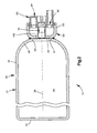
- FIG. 1 is a schematic illustration of a vehicle occupant protection apparatus embodying the present invention
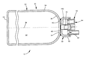
- FIG. 2 is an enlarged sectional view of an inflator that forms part of the apparatus of FIG. 1;
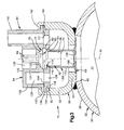
- FIG. 3 is a further enlarged view of a portion of the inflator of FIG. 2;
- FIG. 4 is a view similar to FIG. 2 showing an inflator in accordance with a second embodiment of the invention
- FIG. 5 is a view similar to FIG. 2 showing an inflator in accordance with a third embodiment of the invention.
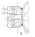
- FIG. 6 is a view similar to FIG. 2 showing an inflator in accordance with a fourth embodiment of the invention.
- FIG. 7 is a view similar to FIG. 2 showing an inflator in accordance with a fifth embodiment of the invention.
- the present invention relates to a vehicle occupant protection apparatus.
- the present invention relates to an inflator for an inflatable vehicle occupant protection device.
- FIG. 1 illustrates an inflator 10 that forms part of a vehicle protection apparatus 11 for helping to protect an occupant of a vehicle 12 .
- the protection apparatus 11 includes an inflatable vehicle occupant protection device in the form of a side curtain 14 .
- the side curtain 14 is mounted adjacent the side structure 16 of the vehicle 12 .
- a fill tube 20 extends into the side curtain 14 .
- the inflator 10 when actuated, directs fluid into the fill tube 20 which, in turn, directs fluid into the inflatable side curtain 14 to inflate the side curtain.
- the side curtain 14 is inflated from a deflated and stowed condition (not shown) to an inflated condition, as illustrated in FIG. 1 . In its inflated condition, the side curtain 14 is positioned between the side structure 16 of the vehicle 12 and a vehicle occupant.
- the side curtain 14 is made of a material having a low permeability so that the side curtain remains inflated for a long period of time, such as seven seconds or longer.
- the vehicle 12 includes a sensor 24 , known in the art, for sensing a side impact to the vehicle and/or a vehicle rollover, to actuate the inflator 10 .
- the sensor 24 may include vehicle electric circuitry for actuating the inflator 10 in response to sensing a side impact to the vehicle and/or a vehicle rollover.
- the sensor 24 provides an electric signal over lead wires 26 to the inflator 10 , when the inflator is to be actuated.
- the inflator 10 (FIG. 2) comprises a source of inflation fluid for the side curtain 14 .
- the inflator 10 includes a container 30 having a generally elongate configuration including a main body portion 32 .
- the main body portion 32 of the container 30 has a tubular, cylindrical configuration including an axially extending, cylindrical side wall 34 .
- the side wall 34 is centered on a longitudinal central axis 36 of the inflator 10 .
- a first end wall 38 of the main body portion 32 has an opening 40 .
- the first end wall 38 , an opposite second end wall 42 , and the side wall 34 define a chamber 44 in the container 30 .
- An end cap 50 is affixed to the first end wall 38 of the main body portion 32 , at a location extending across the opening 40 .
- the end cap 50 is connected to the main body portion 32 in any suitable manner known in the art, such as by friction welding, laser welding, brazing or screw threads.
- the end cap 50 (FIGS. 2 and 3) has a generally cup-shaped configuration including an axially extending, cylindrical side wall 52 and an annular end wall 54 .
- a rupturable closure member 60 such as a rupture disk, is affixed to the end wall 54 of the end cap 50 by a laser weld.
- the rupture disk 60 could, however, be connected to the end cap 50 in any manner well known in the art, such as by brazing, projection welding or electron beam welding.
- the rupture disk 60 could also be formed in one piece with the end cap 50 .
- the rupture disk 60 is centered on the axis 36 and blocks fluid flow through the opening 40 .
- the chamber 44 contains pressurized inflation fluid.
- the inflation fluid stored in the chamber 44 preferably includes helium at a storage pressure within the range of about 4,000 psi to about 7,000 psi.
- the inflation fluid may, however, have any other composition and storage pressure suitable for inflating the side curtain 14 .
- the inflator 10 includes an initiator 70 .
- the initiator 70 is of a known design including a support portion 72 (FIG. 3) and a cylindrical main body portion 74 that projects from the support portion.
- the main body portion 74 and the support portion 72 of the initiator 70 are covered in a deformable material 76 , such as molded nylon.
- the support portion 72 of the initiator 70 has first and second frustoconical surfaces 78 and 80 that extend, in opposite directions along the axis 36 , from a cylindrical outer side surface 82 of the support portion.
- a pair of terminal pins 84 extend from the support portion 72 , in a direction away from the main body portion 74 of the initiator 70 .
- the inflator 10 includes a retainer 90 for retaining the initiator 70 on the container 30 .
- the retainer 90 includes first and second retainer parts 92 and 94 .
- the first and second retainer parts 92 and 94 are separate members that are movable relative to each other when they are not connected with the container 30 .
- the first retainer part 92 is made from metal and has a disc-shaped main body portion 100 including parallel, radially extending inner and outer major side surfaces 102 and 104 .
- a mounting flange 106 extends radially outward from the main body portion 100 .
- a plurality of fluid outlet openings 108 are formed in the main body portion 100 of the first retainer part 92 .
- the fluid outlet openings 108 are circular in shape and are disposed in a circular array centered on the axis 36 .
- the fluid outlet openings 108 extend axially between the inner and outer major side surfaces 102 and 104 .
- the first retainer part 92 has a central surface 110 that defines a central opening 112 in the first retainer part.
- One portion 114 of the central opening 112 is formed as an annular notch, opening into the outer side surface 104 , for receiving a portion of the initiator 70 , as described below.
- Another portion 116 of the central opening 112 is formed as an annular notch, opening into the inner side surface 102 , for receiving a portion of a support barrel 150 , as described below.
- the second retainer part 94 or outer retainer part, is made from metal and has a main body portion 120 with a radially extending inner major side surface 121 .
- a mounting flange 122 extends radially outward from the main body portion 120 .
- the mounting flange 122 on the second retainer part 94 is the same diameter as the mounting flange 106 on the first retainer part 92 .
- the second retainer part 94 includes cylindrical inner and outer walls 124 and 126 that extend parallel to the axis 36 .
- the inner and outer walls 124 and 126 define between them an annular collection chamber 128 .
- the inner wall 124 defines, radially inward of the inner wall, a chamber 130 for receiving a portion of the initiator 70 .
- the inner wall 124 has a frustoconical surface 132 centered on the axis 36 .
- the second retainer part 94 includes an outlet tube 140 .
- the outlet tube 140 has a cylindrical configuration and projects from the second retainer part 94 , at one circumferential location on the second retainer part.
- the outlet tube 140 extends parallel to the longitudinal central axis 36 of the inflator 10 .
- the outlet tube 140 is in fluid communication with the collection chamber 128 , so that fluid flowing into the collection chamber can exit the second retainer part 94 through the outlet tube.
- the support barrel 150 is made from metal and has a cylindrical side wall 152 with a first end portion 154 .
- the side wall 152 is capped at its end opposite the first end portion 154 by a radially extending end wall 156 .
- a circular central opening 158 is formed in the end wall 156 of the support barrel 150 .
- the inflator 10 is assembled by first welding the rupture disk 60 to the end cap 50 .
- the subassembly of the end cap 50 and rupture disk 60 is then welded to the main body portion 32 of the container 30 .
- the end portion 154 of the side wall 152 of the support barrel 150 is pressed into the notch 116 in the inner side surface 102 of the first retainer part 92 .
- the support barrel 150 is, thereby, positioned on the first retainer part 92 for movement with the first retainer part.
- the subassembly of the first retainer part 92 and the support barrel 150 is inserted into the end cap 50 of the inflator 10 .
- the main body portion 100 of the first retainer part 92 has an interference fit with the side wall 52 of the end cap 50 .
- the mounting flange 106 of the first retainer part 92 engages a stop surface 160 on the side wall 52 .
- the end wall 156 of the support barrel 150 is located adjacent the closure member 60 .
- the initiator 70 is then fitted into the central opening 110 of the first retainer part 92 .
- the initiator 70 is self-centering in the first retainer part 92 .
- the support portion 72 of the initiator 70 is received in the notch 114 in the first retainer part 92 .
- the main body portion 74 of the initiator 70 extends within the support barrel 150 .
- the second retainer part 94 is then fitted onto the container 30 .
- the frustoconical surface 132 on the second retainer part 94 engages the support portion 72 of the initiator 70 .
- the inner major side surface 121 of the second retainer part 94 engages the outer major side surface 104 of the first retainer part 92 .
- the mounting flanges 106 and 122 of the retainer parts 92 and 94 overlie each other.
- a projecting portion 162 of the end wall 52 of the end cap 50 is deformed radially inwardly and crimped onto the mounting flange 122 of the second retainer part 94 to secure the retainer 90 , and thereby the initiator 70 , on the container 30 .
- the retainer 90 may be welded to the end cap 50 of the container 30 .
- the initiator 70 is thus clamped between the first retainer part 92 and the second retainer part 94 .
- the metal from which the first and second retainer parts 92 and 94 are made presses into, and deforms, the plastic outer covering of the support portion 72 of the initiator 70 .
- This engagement of the retainer 90 with the initiator 70 creates a fluid-tight seal between the initiator and the retainer.
- the closure member 60 When the chamber 44 is not filled with inflation fluid, the closure member 60 is a flat disk and is spaced from the end wall 156 of the support barrel 150 . During the subsequent loading of the closure member 60 by the pressure of inflation fluid introduced into the chamber 44 through a fill opening (not shown), the closure member is stressed and undergoes plastic deformation into contact with the end wall 156 of the support barrel 150 . The closure member 60 deforms into the shape shown in FIG. 3 .
- the force of the inflation fluid in the chamber 44 presses the support barrel 150 firmly into engagement with the first retainer part 92 .
- the support barrel 150 is thus mounted in a load bearing relationship between the closure member 60 and the first retainer part 92 .
- the first retainer part 92 transmits the storage pressure force through the second retainer part 94 to the end cap 50 .
- the initiator 70 Upon receipt of an electric signal from the sensor 24 , the initiator 70 is actuated in a known manner to produce a shock wave and combustion products.
- the shock wave and combustion products flow through the interior of the support barrel 150 into engagement with the closure member 60 and rupture the closure member.
- Inflation fluid flows through the opening 40 in the container 30 and into the end cap 50 .
- the inflation fluid then flows through the fluid outlet openings 108 in the first retainer part 92 and into the collection chamber 128 of the second retainer part 94 .
- the collection chamber 128 of the second retainer part 94 directs the inflation fluid into the outlet tube 140 .
- the inflation fluid exits the inflator 10 through the outlet tube 140 and thereafter flows to the side curtain 14 to inflate the side curtain.
- the inflation fluid exits the inflator 10 in a direction parallel to the longitudinal axis 36 of the inflator.
- FIG. 4 illustrates a portion of an inflator 10 a constructed in accordance with a second embodiment of the invention. Portions of the inflator 10 a that are the same as, or similar to, corresponding portions of the inflator 10 are given the same reference numerals with the suffix “a” attached.
- an initiator 70 a is clamped between first and second retainer parts 92 a and 94 a .
- the second retainer part 94 a does not include a fluid outlet tube, like the fluid outlet tube 140 (FIG. 3 ). Instead, the second retainer part 94 a (FIG. 4) has a plurality of fluid outlet openings 166 that are aligned with fluid outlet openings 108 a in the first retainer part 92 a .
- the fluid outlet openings 166 in the second retainer part 94 a open into a chamber 168 in a diffuser 170 .
- the diffuser 170 is a tubular member, preferably made from sheet metal, that is crimped onto the end cap 50 a .
- the diffuser 170 has a relatively wide collection portion 172 that extends around the retainer 90 a and the initiator 70 a .
- An outlet tube 174 extends from the collection portion 172 .
- Operation of the inflator 10 a is similar to operation of the inflator 10 .
- the combustion products of the initiator are directed through the support barrel 150 a into engagement with the closure member 60 a .
- the closure member 60 a ruptures, enabling inflation fluid to flow into the end cap 50 a , through the aligned openings 108 a and 166 in the retainer parts 92 a and 94 , into the chamber 168 of the diffuser 170 .
- the inflation fluid flows out of the inflator 10 a through the outlet tube 174 of the diffuser 170 , in a direction parallel to the longitudinal axis 36 a of the inflator.
- FIG. 5 illustrates a portion of an inflator 10 b constructed in accordance with a third embodiment of the invention. Portions of the inflator 10 b that are the same as, or similar to, corresponding portions of the inflator 10 are given the same reference numerals with the suffix “b” attached.
- the inflator 10 b includes a retainer 90 b .
- the retainer 90 b comprises a first retainer part in the form of a support barrel 150 b , and a second retainer part 94 b .
- the second retainer part 94 b has a configuration similar to that of the second retainer part 94 a of the inflator 10 a (FIG. 4 ).
- the second retainer part 94 b (FIG. 5) supports an initiator 70 b having a deformable plastic covering 76 b.
- the second retainer part 94 b has an annular notch 116 b that is presented toward the closure member 60 b .
- the notch 116 b receives a flared end portion 154 b of a support barrel 150 b .
- the end portion 154 b of the support barrel 150 b also engages the plastic covering 76 b of the initiator 70 b .
- the dimensions of the support barrel 150 b , initiator 70 b , and second retainer part 94 b are selected so that, in assembly of the inflator 10 b , the support barrel initially presses against only the initiator, and not the second retainer part, until the fluid force on the closure member 60 b loads the support barrel 150 b .
- the flared end portion 154 of the support barrel 150 b effects a fluid tight-seal against the initiator 70 b.
- FIG. 6 illustrates a portion of an inflator 10 c constructed in accordance with a fourth embodiment of the invention. Portions of the inflator 10 c that are the same as, or similar to, corresponding portions of the inflator 10 are given the same reference numerals with the suffix “c” attached. Portions of the inflator 10 c that were not introduced with reference numerals in discussing the inflator 10 will have values in the two hundreds with the suffix “c” attached.
- the inflator 10 c includes a retainer 90 c .
- the retainer 90 c comprises a first retainer part in the form of a support barrel 150 c , and a second retainer part 94 c .
- the support barrel 150 c has a side wall 152 c and an end wall 156 c .
- the side wall 152 c includes a first cylindrical portion 202 c , a second cylindrical portion 204 c , and a frustoconical portion 206 c that connects the first and second cylindrical portions.
- the first cylindrical portion 202 c has a diameter that is less than a diameter of the second cylindrical portion 204 c .
- the end wall 156 c closes one end of the first cylindrical portion 202 c .
- An opening 158 c extends through the central portion of the end wall 156 c .
- a second end of the first cylindrical portion 202 c connects to a narrow end of the frustoconical portion 206 c .
- the second cylindrical portion 204 c extends from a wide end of the frustoconical portion 206 c .
- the second cylindrical portion 204 c terminates at an annular end surface 208 c.
- the second retainer part 94 c has a cylindrical main body portion 120 c .
- the main body portion 120 c includes cylindrical inner and outer walls 124 c and 126 c .
- the inner and outer walls 124 c and 126 c define between them an annular collection chamber 128 c .
- An end wall 210 c extends between the inner and outer walls 124 c and 126 c on a first end of the second retainer part 94 c .
- An opening in the end wall 210 c forms a gas outlet 214 c .
- the gas outlet 214 c is in fluid communication with the collection chamber 128 c . Fluid flowing from the collection chamber 128 c through the gas outlet 214 c flows in a direction parallel to the longitudinal axis 36 c.
- the outer wall 126 c terminates at an annular end surface 216 c , opposite the end wall 210 c .
- An annular notch 218 c extends between the end surface 216 c and a radially outer surface 220 c of the outer wall 126 c .
- a radial notch surface 222 c and an axial notch surface 224 c define the annular notch 218 c.
- the inner wall 124 c defines a chamber 130 c for receiving a portion of the initiator 70 c .
- the chamber 130 c is located radially inwardly of the inner wall 124 c .
- the inner wall 124 c terminates at an annular end surface 226 c , opposite the end wall 210 c .
- An annular notch 228 c extends between the end surface 226 c and a radially outer surface 230 c of the inner wall 124 c .
- a radial notch surface 232 c and an axial notch surface 234 c define the annular notch 228 c .
- a portion of the inner wall 124 c between the axial notch surface 234 c and a radially inner surface 236 c of the inner wall 124 c is bendable.
- the support portion 72 c of the initiator 70 c is positioned in the chamber 130 c .
- the support portion 72 c of the initiator 70 c has a plastic outer covering.
- the portion of the inner wall 124 c between the axial notch surface 234 c and the radially inner surface 236 c is crimped around the support portion 72 c of the inflator 70 c . This engagement of the second retainer part 94 c with the initiator 70 c creates a fluid-tight seal between the initiator and the retainer 90 c.
- the second cylindrical portion 204 c of the support barrel 150 c is then positioned around the crimped portion of the inner wall 124 c .
- the annular end surface 208 c of the second cylindrical portion 204 c of the support barrel contacts the radial notch surface 232 c of the inner wall 124 c of the second retainer part 94 c .
- the second cylindrical portion 204 c of the support barrel 150 c also abuts the axial notch surface 234 c of the inner wall 124 c of the second retainer part 94 c .
- the second retainer part 94 c is positioned on the end cap 50 c of the inflator 10 c such that the end surface 216 c of the outer wall 126 c contacts the stop surface 160 c on the side wall 52 c of the end cap 50 c .
- the second retainer part 94 c is then laser welded to the end cap 50 c .
- the closure member deforms and contacts the end wall 156 c of the support barrel 150 c.
- Operation of the inflator 10 c of FIG. 6 is similar to operation of inflator 10 .
- the combustion products of the initiator are directed through the support barrel 150 c into engagement with the closure member 60 c .
- the closure member 60 c ruptures, enabling inflation fluid to flow into the end cap 50 c .
- the inflation fluid flows from the end cap 50 c into the chamber 128 c of the second retainer part 94 c .
- the inflation fluid then flows out of the inflator 10 c through the gas outlet 214 c , in a direction parallel to the longitudinal axis 36 c of the inflator 10 c.
- FIG. 7 illustrates a portion of an inflator 10 d constructed in accordance with a fifth embodiment of the invention. Portions of the inflator 10 d that are the same as, or similar to, corresponding portions of the inflator 10 are given the same reference numerals with the suffix “d” attached. Portions of the inflator 10 d that were not introduced with reference numerals in discussing the inflator 10 will have values in the three hundreds with the suffix “d” attached.
- the inflator 10 d includes a retainer 90 d .
- the retainer 90 d comprises a first retainer part in the form of a support barrel 150 d , and a second retainer part 94 d .
- the support barrel 150 d has a side wall 152 d and an end wall 156 d .
- the side wall 152 d includes a first cylindrical portion 302 d , a second cylindrical portion 304 d , and a frustoconical portion 306 d that connects the first and second cylindrical portions.
- the first cylindrical portion 302 d has a diameter that is less than a diameter of the second cylindrical portion 304 d .
- the end wall 156 d closes one end of the first cylindrical portion 302 d .
- An opening 158 d extends through a central portion of the end wall 156 d .
- a second end of the first cylindrical portion 302 d connects to a narrow end of the frustoconical portion 306 d .
- the second cylindrical portion 304 d extends from a wide end of the frustoconical portion 306 d .
- the second cylindrical portion 304 d terminates at an annular end surface 308 d.
- the second retainer part 94 d has a cylindrical main body portion 120 b .
- the main body portion 120 d includes first and second axial end surfaces 310 d and 312 d , respectively, and radially inner and outer surfaces 314 d and 316 d , respectively.
- a gas outlet 318 d extends from the second axial end surface 312 d to the first axial end surface 310 d through the second retainer part 94 d between the radially inner and outer surfaces 314 d and 316 d . Fluid flowing through the gas outlet 318 d flows in a direction parallel to the longitudinal axis 36 d.
- An annular notch 320 d is formed on the second axial end surface 312 d at a union with the radially outer surface 316 d .
- the annular notch 320 d is defined by an axial notch surface 322 d and a radial notch surface 324 d.
- the radially inner surface 314 d of the second retainer part 94 d defines a chamber 130 d for receiving a portion of an initiator 70 d .
- the chamber 130 d narrows as it extends axially away from the second end surface 312 d of the second retainer part 94 d .
- the narrowing of the chamber 130 d is the result of a frustoconical portion 326 d of the inner surface 314 d , which projects radially inward.
- An annular projection 328 d projects axially outwardly of the second axial end surface 312 d of the second retainer part 94 d.
- the support portion 72 d of the initiator 70 d is clamped between the frustoconical portion 306 d of the support barrel 150 d and the frustoconical portion 326 d of the inner surface 314 d of the second retainer part 94 d .
- the annular projection 328 d is then crimped around the frustoconical portion 306 d of the support barrel 150 d to secure the support barrel 150 d to the second retainer part 94 d .
- This engagement of the second retainer part 94 d with the initiator 70 d creates a fluid-tight seal between the initiator and the retainer 90 d.
- the second retainer part 94 b is positioned on the end cap 50 d of the inflator 10 d such that the second axial end surface 312 d contacts the stop surface 160 d on the side wall 52 d of the end cap 50 d .
- the second retainer part 94 d is then laser welded to the end cap 50 d .
- the closure member deforms and contacts the end wall 156 d of the support barrel 150 d.
- Operation of the inflator 10 d of FIG. 7 is similar to operation of inflator 10 .
- the combustion products of the initiator are directed through the support barrel 150 d into engagement with the closure member 60 d .
- the closure member 60 d ruptures, enabling inflation fluid to flow into the end cap 50 d .
- the inflation then flows out of the inflator 10 d through the gas outlet 318 d , in a direction parallel to the longitudinal axis 36 d of the inflator.
- the inflator 10 is shown being used with a side curtain 14 , the inflator could be used in any known inflatable vehicle occupant protection device, such as frontal or side impact air bags, inflatable seat belts, inflatable knee bolsters, inflatable air bags to operate knee bolsters, and inflatable head liners.
- the invention is applicable to inflators that do not use a support member, such as the support barrel 150 , to support a rupturable member.
Landscapes
- Physics & Mathematics (AREA)
- Fluid Mechanics (AREA)
- Engineering & Computer Science (AREA)
- Mechanical Engineering (AREA)
- Air Bags (AREA)
Abstract
Description
Claims (16)
Priority Applications (1)
| Application Number | Priority Date | Filing Date | Title |
|---|---|---|---|
| US09/925,711 US6830264B2 (en) | 2001-02-09 | 2001-08-09 | Air bag inflator with initiator retainer |
Applications Claiming Priority (2)
| Application Number | Priority Date | Filing Date | Title |
|---|---|---|---|
| US09/780,751 US20020109339A1 (en) | 2001-02-09 | 2001-02-09 | Air bag inflator with initiator retainer |
| US09/925,711 US6830264B2 (en) | 2001-02-09 | 2001-08-09 | Air bag inflator with initiator retainer |
Related Parent Applications (1)
| Application Number | Title | Priority Date | Filing Date |
|---|---|---|---|
| US09/780,751 Continuation-In-Part US20020109339A1 (en) | 2001-02-09 | 2001-02-09 | Air bag inflator with initiator retainer |
Publications (2)
| Publication Number | Publication Date |
|---|---|
| US20020109340A1 US20020109340A1 (en) | 2002-08-15 |
| US6830264B2 true US6830264B2 (en) | 2004-12-14 |
Family
ID=25120569
Family Applications (2)
| Application Number | Title | Priority Date | Filing Date |
|---|---|---|---|
| US09/780,751 Abandoned US20020109339A1 (en) | 2001-02-09 | 2001-02-09 | Air bag inflator with initiator retainer |
| US09/925,711 Expired - Lifetime US6830264B2 (en) | 2001-02-09 | 2001-08-09 | Air bag inflator with initiator retainer |
Family Applications Before (1)
| Application Number | Title | Priority Date | Filing Date |
|---|---|---|---|
| US09/780,751 Abandoned US20020109339A1 (en) | 2001-02-09 | 2001-02-09 | Air bag inflator with initiator retainer |
Country Status (2)
| Country | Link |
|---|---|
| US (2) | US20020109339A1 (en) |
| DE (1) | DE10204627B4 (en) |
Cited By (9)
| Publication number | Priority date | Publication date | Assignee | Title |
|---|---|---|---|---|
| US20040041383A1 (en) * | 2002-08-30 | 2004-03-04 | Trw Airbag Systems Gmbh | Hybrid gas generator |
| US20040070186A1 (en) * | 2002-09-03 | 2004-04-15 | Trw Airbag Systems Gmbh | Method of producing a gas generator housing part, gas generator including such housing part and gas bag module |
| US20050006887A1 (en) * | 2003-07-07 | 2005-01-13 | Kent Barker | Airbag initiator cover attachment apparatus and method |
| US20050230950A1 (en) * | 2004-04-20 | 2005-10-20 | Trw-Vehicle Safety Systems Inc. | Inflator with stamped end cap |
| US20060214404A1 (en) * | 2004-10-28 | 2006-09-28 | Blackburn Jeffery S | Pressurized gas release mechanism |
| US20070186797A1 (en) * | 2004-03-30 | 2007-08-16 | Nippon Kayaku Kabushike Kaisha | Gas generator |
| US20090020990A1 (en) * | 2007-07-22 | 2009-01-22 | Key Safety Systems, Inc. | Venting device for an airbag inflator |
| US20100117345A1 (en) * | 2008-11-13 | 2010-05-13 | Mayville Brian A | Initiator housing assembly |
| US11208072B2 (en) * | 2017-07-14 | 2021-12-28 | Daicel Corporation | Ejector and gas generator |
Families Citing this family (8)
| Publication number | Priority date | Publication date | Assignee | Title |
|---|---|---|---|---|
| JP4864251B2 (en) | 2001-02-26 | 2012-02-01 | 株式会社ダイセル | Inflator |
| DE10300757A1 (en) * | 2003-01-11 | 2005-06-02 | Adam Opel Ag | Airbag module for a motor vehicle with an airbag module housing and method for producing a welded connection between an inflation opening of an airbag and a gas outlet opening of an airbag module housing |
| JP2005343341A (en) * | 2004-06-03 | 2005-12-15 | Daicel Chem Ind Ltd | Gas generator for airbag |
| US20060006632A1 (en) * | 2004-06-03 | 2006-01-12 | Daicel Chemical Industries, Ltd. | Gas generator for air bag |
| DE102007010066A1 (en) * | 2007-02-28 | 2008-09-18 | Autoliv Development Ab | Inflation device for airbag, has compressed gas storage and ventilation opening, which are closed with diaphragm, on whose outer side actuator is arranged |
| JP4916992B2 (en) * | 2007-09-28 | 2012-04-18 | 株式会社ダイセル | Inflator |
| US9051225B1 (en) * | 2009-06-12 | 2015-06-09 | Tk Holdings Inc. | Gas generator |
| US8979121B2 (en) * | 2011-03-18 | 2015-03-17 | Autoliv Asp, Inc. | Pyrotechnic inflator with central diffuser and composite overwrap |
Citations (19)
| Publication number | Priority date | Publication date | Assignee | Title |
|---|---|---|---|---|
| US5056815A (en) * | 1989-07-25 | 1991-10-15 | Bayern-Chemie, Gesellschaft Fur Flugchemische Antriebe Mbh Gmbh | Arrangement for an airbag gas generator |
| US5351988A (en) | 1990-11-27 | 1994-10-04 | Alliedsignal Inc. | Hybrid inflator with staged inflation capability |
| US5590906A (en) | 1993-10-13 | 1997-01-07 | Trw Vehicle Safety Systems Inc. | Vehicle occupant restraint inflator |
| US5609362A (en) | 1996-04-19 | 1997-03-11 | Trw Vehicle Safety Systems Inc. | Inflator |
| US5669631A (en) | 1996-11-18 | 1997-09-23 | Morton International, Inc. | Liquid propellant airbag inflator with auto injection combustion chamber |
| US5794973A (en) * | 1996-12-04 | 1998-08-18 | Trw Vehicle Safety Systems Inc. | Dual stage air bag inflator |
| US5803493A (en) * | 1997-04-17 | 1998-09-08 | Morton International Inc. | Hybrid blowdown inflator with reduced pressure buildup |
| US5839754A (en) | 1995-06-08 | 1998-11-24 | Honda R&D Co. Ltd. | Multiple stage airbag gas generator |
| US5913537A (en) * | 1995-06-09 | 1999-06-22 | Trw Vehicle Safety Systems Inc. | Hybrid inflator including non-metallic nitrogen containing ignitable material |
| US6010152A (en) * | 1998-03-31 | 2000-01-04 | Trw Inc. | Air bag inflator |
| US6029995A (en) * | 1998-04-09 | 2000-02-29 | Trw Vehicle Safety Systems Inc. | Vehicle occupant protection apparatus |
| US6120058A (en) | 1996-08-23 | 2000-09-19 | Trw Vehicle Safety Systems Inc. | Air bag inflator |
| US6206420B1 (en) | 1995-10-31 | 2001-03-27 | Autoliv Development Ab | Device for introducing pressurized gas into a vehicle safety device |
| US6217065B1 (en) * | 1999-08-10 | 2001-04-17 | Trw Inc. | Inflator |
| US6237940B1 (en) | 2000-02-29 | 2001-05-29 | Trw Inc. | Inflator for side curtain |
| US6295935B1 (en) | 1998-04-27 | 2001-10-02 | Trw Inc. | Initiator for air bag inflator |
| US6382668B1 (en) | 2000-11-16 | 2002-05-07 | Trw Vehicle Safety Systems Inc. | Air bag inflator |
| US6386581B1 (en) * | 1999-12-13 | 2002-05-14 | Toyota Jidosha Kabushiki Kaisha | Controlling deployment of air-bag body of head-protection air-bag device |
| US6412811B1 (en) | 1999-02-26 | 2002-07-02 | Trw Inc. | Inflator |
Family Cites Families (1)
| Publication number | Priority date | Publication date | Assignee | Title |
|---|---|---|---|---|
| US6062599A (en) * | 1998-05-12 | 2000-05-16 | Trw Vehicle Safety Systems Inc. | Air bag inflator |
-
2001
- 2001-02-09 US US09/780,751 patent/US20020109339A1/en not_active Abandoned
- 2001-08-09 US US09/925,711 patent/US6830264B2/en not_active Expired - Lifetime
-
2002
- 2002-02-05 DE DE10204627A patent/DE10204627B4/en not_active Expired - Fee Related
Patent Citations (19)
| Publication number | Priority date | Publication date | Assignee | Title |
|---|---|---|---|---|
| US5056815A (en) * | 1989-07-25 | 1991-10-15 | Bayern-Chemie, Gesellschaft Fur Flugchemische Antriebe Mbh Gmbh | Arrangement for an airbag gas generator |
| US5351988A (en) | 1990-11-27 | 1994-10-04 | Alliedsignal Inc. | Hybrid inflator with staged inflation capability |
| US5590906A (en) | 1993-10-13 | 1997-01-07 | Trw Vehicle Safety Systems Inc. | Vehicle occupant restraint inflator |
| US5839754A (en) | 1995-06-08 | 1998-11-24 | Honda R&D Co. Ltd. | Multiple stage airbag gas generator |
| US5913537A (en) * | 1995-06-09 | 1999-06-22 | Trw Vehicle Safety Systems Inc. | Hybrid inflator including non-metallic nitrogen containing ignitable material |
| US6206420B1 (en) | 1995-10-31 | 2001-03-27 | Autoliv Development Ab | Device for introducing pressurized gas into a vehicle safety device |
| US5609362A (en) | 1996-04-19 | 1997-03-11 | Trw Vehicle Safety Systems Inc. | Inflator |
| US6120058A (en) | 1996-08-23 | 2000-09-19 | Trw Vehicle Safety Systems Inc. | Air bag inflator |
| US5669631A (en) | 1996-11-18 | 1997-09-23 | Morton International, Inc. | Liquid propellant airbag inflator with auto injection combustion chamber |
| US5794973A (en) * | 1996-12-04 | 1998-08-18 | Trw Vehicle Safety Systems Inc. | Dual stage air bag inflator |
| US5803493A (en) * | 1997-04-17 | 1998-09-08 | Morton International Inc. | Hybrid blowdown inflator with reduced pressure buildup |
| US6010152A (en) * | 1998-03-31 | 2000-01-04 | Trw Inc. | Air bag inflator |
| US6029995A (en) * | 1998-04-09 | 2000-02-29 | Trw Vehicle Safety Systems Inc. | Vehicle occupant protection apparatus |
| US6295935B1 (en) | 1998-04-27 | 2001-10-02 | Trw Inc. | Initiator for air bag inflator |
| US6412811B1 (en) | 1999-02-26 | 2002-07-02 | Trw Inc. | Inflator |
| US6217065B1 (en) * | 1999-08-10 | 2001-04-17 | Trw Inc. | Inflator |
| US6386581B1 (en) * | 1999-12-13 | 2002-05-14 | Toyota Jidosha Kabushiki Kaisha | Controlling deployment of air-bag body of head-protection air-bag device |
| US6237940B1 (en) | 2000-02-29 | 2001-05-29 | Trw Inc. | Inflator for side curtain |
| US6382668B1 (en) | 2000-11-16 | 2002-05-07 | Trw Vehicle Safety Systems Inc. | Air bag inflator |
Non-Patent Citations (1)
| Title |
|---|
| Co-pending U.S. Appl. No. 09/515,481, filed Aug. 10, 1999 entitled "Inflator". |
Cited By (17)
| Publication number | Priority date | Publication date | Assignee | Title |
|---|---|---|---|---|
| US20040041383A1 (en) * | 2002-08-30 | 2004-03-04 | Trw Airbag Systems Gmbh | Hybrid gas generator |
| US20040070186A1 (en) * | 2002-09-03 | 2004-04-15 | Trw Airbag Systems Gmbh | Method of producing a gas generator housing part, gas generator including such housing part and gas bag module |
| US7152321B2 (en) * | 2002-09-03 | 2006-12-26 | Trw Airbag Systems Gmbh | Method of producing a gas generator housing part, gas generator including such housing part and gas bag module |
| US20050006887A1 (en) * | 2003-07-07 | 2005-01-13 | Kent Barker | Airbag initiator cover attachment apparatus and method |
| US7077428B2 (en) * | 2003-07-07 | 2006-07-18 | Autoliv Asp, Inc. | Airbag initiator cover attachment apparatus and method |
| US20070186797A1 (en) * | 2004-03-30 | 2007-08-16 | Nippon Kayaku Kabushike Kaisha | Gas generator |
| US7516701B2 (en) * | 2004-03-30 | 2009-04-14 | Nippon Kayaku Kabushiki Kaisha | Gas generator |
| US20050230950A1 (en) * | 2004-04-20 | 2005-10-20 | Trw-Vehicle Safety Systems Inc. | Inflator with stamped end cap |
| US8104791B2 (en) | 2004-10-28 | 2012-01-31 | Automotive Systems Laboratory, Inc. | Pressurized gas release mechanism |
| US20060214404A1 (en) * | 2004-10-28 | 2006-09-28 | Blackburn Jeffery S | Pressurized gas release mechanism |
| US7597354B2 (en) * | 2004-10-28 | 2009-10-06 | Automotive Systems Laboratory, Inc. | Pressurized gas release mechanism |
| US20100019475A1 (en) * | 2004-10-28 | 2010-01-28 | Blackburn Jeffery S | Pressurized gas release mechanism |
| US20090020990A1 (en) * | 2007-07-22 | 2009-01-22 | Key Safety Systems, Inc. | Venting device for an airbag inflator |
| US7658406B2 (en) | 2007-07-22 | 2010-02-09 | Key Safety Systems, Inc. | Venting device for an airbag inflator |
| US20100117345A1 (en) * | 2008-11-13 | 2010-05-13 | Mayville Brian A | Initiator housing assembly |
| US8172262B2 (en) | 2008-11-13 | 2012-05-08 | Tk Holdings, Inc. | Initiator housing assembly |
| US11208072B2 (en) * | 2017-07-14 | 2021-12-28 | Daicel Corporation | Ejector and gas generator |
Also Published As
| Publication number | Publication date |
|---|---|
| DE10204627A1 (en) | 2002-10-31 |
| US20020109340A1 (en) | 2002-08-15 |
| DE10204627B4 (en) | 2009-08-13 |
| US20020109339A1 (en) | 2002-08-15 |
Similar Documents
| Publication | Publication Date | Title |
|---|---|---|
| US6830264B2 (en) | Air bag inflator with initiator retainer | |
| US7131663B1 (en) | Inflator for inflatable vehicle occupant protection device | |
| JP3181870B2 (en) | Hybrid inflator for airbag | |
| US6295935B1 (en) | Initiator for air bag inflator | |
| US6854760B2 (en) | Cylindrical passenger airbag module | |
| KR0131158B1 (en) | Isolation member for air bag inflator | |
| US6217065B1 (en) | Inflator | |
| EP0712766B1 (en) | Side impact air bag inflator | |
| KR20040062990A (en) | Opening device for a cold gas inflator | |
| US6644206B2 (en) | Electrically actuatable initiator with output charge | |
| US6250665B1 (en) | Retainer structure for an inflatable vehicle occupant protection device | |
| US20020145274A1 (en) | Air bag module with vent | |
| US7140638B2 (en) | Inflator filter retainer | |
| US20060103123A1 (en) | Inflator with shock wave focusing structure | |
| US20050230950A1 (en) | Inflator with stamped end cap | |
| US5785348A (en) | Diffusor cup for an inflator device which is used to inflate an airbag in an airbag system | |
| US6176249B1 (en) | Inflator | |
| US20050040633A1 (en) | Stored gas inflator with fill valve assembly | |
| JP3977812B2 (en) | Cold gas inflator opening device | |
| US7093852B2 (en) | Inflator | |
| US20070257476A1 (en) | Inflator with improved rupture disk support | |
| US20050230948A1 (en) | Inflator with weld spatter collection | |
| US20060043714A1 (en) | Apparatus for providing inflator thrust neutrality |
Legal Events
| Date | Code | Title | Description |
|---|---|---|---|
| AS | Assignment |
Owner name: TRW INC., OHIO Free format text: ASSIGNMENT OF ASSIGNORS INTEREST;ASSIGNOR:AL-ARNIN, AHMAD K.;REEL/FRAME:012084/0219 Effective date: 20010802 |
|
| AS | Assignment |
Owner name: JPMORGAN CHASE BANK, NEW YORK Free format text: THE US GUARANTEE AND COLLATERAL AGREEMENT;ASSIGNOR:TRW AUTOMOTIVE U.S. LLC;REEL/FRAME:014022/0720 Effective date: 20030228 |
|
| STCF | Information on status: patent grant |
Free format text: PATENTED CASE |
|
| FPAY | Fee payment |
Year of fee payment: 4 |
|
| FPAY | Fee payment |
Year of fee payment: 8 |
|
| AS | Assignment |
Owner name: JPMORGAN CHASE BANK, N.A., AS COLLATERAL AGENT, NE Free format text: SECURITY AGREEMENT;ASSIGNORS:TRW VEHICLE SAFETY SYSTEMS INC.;TRW AUTOMOTIVE U.S. LLC;KELSEY-HAYES COMPANY;REEL/FRAME:029529/0534 Effective date: 20120928 Owner name: JPMORGAN CHASE BANK, N.A., AS COLLATERAL AGENT, NEW YORK Free format text: SECURITY AGREEMENT;ASSIGNORS:TRW VEHICLE SAFETY SYSTEMS INC.;TRW AUTOMOTIVE U.S. LLC;KELSEY-HAYES COMPANY;REEL/FRAME:029529/0534 Effective date: 20120928 |
|
| AS | Assignment |
Owner name: TRW INTELLECTUAL PROPERTY CORP., MICHIGAN Free format text: RELEASE OF SECURITY INTEREST;ASSIGNOR:JPMORGAN CHASE BANK, N.A.;REEL/FRAME:031645/0697 Effective date: 20131028 Owner name: TRW VEHICLE SAFETY SYSTEMS INC., MICHIGAN Free format text: RELEASE OF SECURITY INTEREST;ASSIGNOR:JPMORGAN CHASE BANK, N.A.;REEL/FRAME:031645/0697 Effective date: 20131028 Owner name: TRW AUTOMOTIVE U.S. LLC, MICHIGAN Free format text: RELEASE OF SECURITY INTEREST;ASSIGNOR:JPMORGAN CHASE BANK, N.A.;REEL/FRAME:031645/0697 Effective date: 20131028 Owner name: KELSEY-HAYES COMPANY, MICHIGAN Free format text: RELEASE OF SECURITY INTEREST;ASSIGNOR:JPMORGAN CHASE BANK, N.A.;REEL/FRAME:031645/0697 Effective date: 20131028 |
|
| FPAY | Fee payment |
Year of fee payment: 12 |