US6826859B1 - Decorative shade for a video display - Google Patents
Decorative shade for a video display Download PDFInfo
- Publication number
- US6826859B1 US6826859B1 US10/721,245 US72124503A US6826859B1 US 6826859 B1 US6826859 B1 US 6826859B1 US 72124503 A US72124503 A US 72124503A US 6826859 B1 US6826859 B1 US 6826859B1
- Authority
- US
- United States
- Prior art keywords
- roller
- decorative shade
- video display
- attached
- blind
- Prior art date
- Legal status (The legal status is an assumption and is not a legal conclusion. Google has not performed a legal analysis and makes no representation as to the accuracy of the status listed.)
- Expired - Fee Related
Links
- 238000005096 rolling process Methods 0.000 claims abstract description 14
- 230000000149 penetrating effect Effects 0.000 claims description 3
- 239000000428 dust Substances 0.000 abstract description 3
- 238000005034 decoration Methods 0.000 abstract description 2
- 239000004973 liquid crystal related substance Substances 0.000 description 6
- 238000010422 painting Methods 0.000 description 2
- 239000004744 fabric Substances 0.000 description 1
- 230000005484 gravity Effects 0.000 description 1
- 230000004048 modification Effects 0.000 description 1
- 238000012986 modification Methods 0.000 description 1
- 230000001681 protective effect Effects 0.000 description 1
- 230000000007 visual effect Effects 0.000 description 1
Images


Classifications
-
- G—PHYSICS
- G09—EDUCATION; CRYPTOGRAPHY; DISPLAY; ADVERTISING; SEALS
- G09F—DISPLAYING; ADVERTISING; SIGNS; LABELS OR NAME-PLATES; SEALS
- G09F11/00—Indicating arrangements for variable information in which the complete information is permanently attached to a movable support which brings it to the display position
- G09F11/18—Indicating arrangements for variable information in which the complete information is permanently attached to a movable support which brings it to the display position the display elements being carried by belts, chains, or the like other than endless
- G09F11/20—Indicating arrangements for variable information in which the complete information is permanently attached to a movable support which brings it to the display position the display elements being carried by belts, chains, or the like other than endless the elements being in the form of stiff flaps, boards, cards or the like
-
- Y—GENERAL TAGGING OF NEW TECHNOLOGICAL DEVELOPMENTS; GENERAL TAGGING OF CROSS-SECTIONAL TECHNOLOGIES SPANNING OVER SEVERAL SECTIONS OF THE IPC; TECHNICAL SUBJECTS COVERED BY FORMER USPC CROSS-REFERENCE ART COLLECTIONS [XRACs] AND DIGESTS
- Y10—TECHNICAL SUBJECTS COVERED BY FORMER USPC
- Y10S—TECHNICAL SUBJECTS COVERED BY FORMER USPC CROSS-REFERENCE ART COLLECTIONS [XRACs] AND DIGESTS
- Y10S248/00—Supports
- Y10S248/917—Video display screen support
- Y10S248/918—Ancillary device support associated with a video display screen
Definitions
- the invention relates to a decorative shade for a video display, and particularly to a decorative shade for a video display, which has artistic features to decorate the video display.
- Video displays are common in households and include computer monitors, televisions and video game monitors. However, the appearance of a computer monitor or a television not in use is a monotonous frame and a dark, blank screen. Therefore, the video display does not have any decorative features when the video display is not used. With video display trends tending toward thin, very large video displays, large-size plasma televisions and liquid crystal displays (LCD) over 40-inches in size have been created and are becoming common. As such, video displays are becoming a larger visual proportion for interior decoration, and the monotonous appearance of video displays is a drawback that most consumers have no choice but to accept.
- LCD liquid crystal displays
- the plasma televisions and the liquid crystal displays are often suspended at high places so they are not easily cleaned. Furthermore, screens on liquid crystal displays are soft and easily damaged. Therefore, a protective, dust-proof device must be used with large-size or pliable video displays such as plasma televisions or liquid crystal displays, respectively.
- the present invention has arisen to provide a decorative shade for a video display to provide dust-proof protection and artistic features at the same time.
- a first objective of the present invention is to provide a decorative shade for a video display, which has artistic features to decorate the video display.
- a second objective of the present invention is to provide a decorative shade for a video display that provides dust-proof protection for the video display.
- FIG. 1 is an exploded perspective view of a first embodiment of a decorative shade for a video display in accordance with the present invention
- FIG. 2 is a side plan view in partial section of the decorative shade in FIG. 1 mounted on a video display;
- FIG. 3 is an operational perspective view of the decorative shade in FIG. 1 mounted on a liquid crystal display
- FIG. 4 is an exploded perspective view of a second embodiment of the decorative shade in accordance with the present invention with a blind that moves transversally;
- FIG. 5 is a side plane view in partial section of a third embodiment of the decorative shade in accordance with the present invention, wherein the shade is formed integrally with the video display case;
- FIG. 6 is a perspective view of the third embodiment of the decorative shade formed on a liquid crystal display
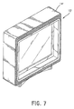
- FIG. 7 is an operational perspective view of the third embodiment of the decorative shade with the blind retracted.
- FIG. 8 is a perspective view of a living room with a video display that has a decorative shade.
- a decorative shade for a video display with a screen comprises a window with an opening to mount to the video display, a rolling device mounted inside the window, and a blind mounted on the roller.
- the window is either detachably mounted on the video display or integrally formed on the video display.
- a first embodiment of the decorative shade in accordance with the present invention comprises a window ( 10 ), a rolling device ( 20 ), and a blind ( 30 ).
- the window ( 10 ) is a rectangular frame and has a front face (not numbered), a rear face (not numbered), a rectangular opening ( 12 ) and a flange ( 14 ).
- the front face of the window ( 10 ) has specific patterns or embossments to make the window ( 10 ) look like a frame for a painting.
- the front and rear faces have a common outer edge, and the flange ( 14 ) is formed around and extending from the outer edge of the rear face and has a top inner face (not numbered), a bottom inner face (not numbered), two inner side-faces (not numbered), two roller brackets ( 16 ) and two optional rails ( 18 ).
- the top inner face has two ends (not numbered).
- the roller brackets ( 16 ) are mounted respectively at opposite ends of the top inner face. Each end bracket ( 16 ) has a hole that aligns with the hole in the other roller bracket ( 16 ).
- the rails ( 18 ) are mounted respectively on the two inner side-faces and guide the blind ( 30 ) when the blind ( 30 ) moves.
- the rolling device ( 20 ) comprises a roller ( 22 ) and a driver ( 24 ).
- the roller ( 22 ) has two ends respectively penetrating the holes in the roller brackets ( 16 ). Thereby, the roller ( 22 ) is suspended at the top inner face of the window ( 10 ).
- the driver ( 24 ) is attached to one end to rotate the roller ( 22 ).
- the driver ( 24 ) may be either electrically or manually driven.
- the driver ( 24 ) is electrically driven by a remote control.
- the blind ( 30 ) wound on the roller ( 22 ) has an attached end (not numbered), a free end (not numbered), two side edges (not numbered), a weighted rod ( 32 ) and an outer surface (not numbered).
- the attached end is attached to the roller ( 22 ), and the free end is wound on or off the roller ( 22 ) to uncover or cover the opening ( 12 ) of the window ( 10 ). Because the roller ( 22 ) is rotated clockwise or counterclockwise by the driver ( 24 ), the blind ( 30 ) is wound off or onto the roller ( 22 ) to selectively cover or uncover the screen ( 42 ).
- the weighted rod ( 32 ) is attached to the free end and has two ends (not numbered).
- the ends of the weighted rod ( 32 ) extend respectively beyond the side edges of the blind ( 30 ) and are slidably mounted respectively in the rails ( 18 ).
- the weighted rod ( 32 ) pulls the blind ( 30 ) down and keeps the blind ( 30 ) flat.
- the outer surface of the blind ( 30 ) has a picture facing the opening ( 12 ) so the window looks like a painting or a decorative picture when the blind ( 30 ) covers the screen ( 42 ).
- the decorative shade is attached to a video display ( 40 ) by pressing the rectangular flange ( 14 ) around the video display ( 40 ).
- the blind ( 30 ) is wound up by the rolling device ( 20 ) to reveal the screen ( 42 ).
- the blind ( 30 ) is unwound to cover and protect the screen ( 42 ).
- the blind ( 30 ) also keeps the video display ( 40 ) free from dust.
- the patterns on the front face of the blind ( 30 ) transform the ii decorative shade to a framed piece of artwork. Thereby, the decorative shade changes a simple covered video display ( 40 ) to a decorative picture.
- a second embodiment of the decorative shade in accordance with the present invention has a blind ( 30 ) that moves transversally inside the window ( 10 ).
- the rolling device ( 20 ) is mounted in one inner side-face of the flange ( 14 ). Since gravity will not pull the blind ( 30 ) over the video display, a closing device ( 35 ) is mounted the inner side-face of the flange ( 14 ) opposite to the rolling device ( 20 ).
- the closing device ( 35 ) has the same elements as the rolling device ( 20 ) including a roller (not numbered) and a driver (not numbered) plus two cords ( 352 ).
- the roller ( 22 ) has two ends (not numbered).
- the cords ( 352 ) are attached between the roller and the weighted rod ( 32 ) (or the blind cloth) respectively at the two ends to keep the blind ( 30 ) straight and flat.
- the closing device ( 35 ) and the rolling device ( 20 ) are operated synchronously in the same rotating direction to extend or retract the blind ( 30 ).
- a third embodiment of the decorative shade in accordance with the present invention has a flange ( 14 ′) of the window ( 10 ′) formed integrally with the video display.
- Other elements in the third embodiment are the same as those in the first and the second embodiments. Therefore, further description would be redundant and is not included.
- the window ( 10 ′′) of the decorative shade attached to a large-size plasma television not only protects and keeps dust off the plasma television but also changes the plasma television to a decorative picture.
Landscapes
- Physics & Mathematics (AREA)
- General Physics & Mathematics (AREA)
- Engineering & Computer Science (AREA)
- Theoretical Computer Science (AREA)
- Devices For Indicating Variable Information By Combining Individual Elements (AREA)
Abstract
A decorative shade for a video display with a screen has a window with an opening to attach to the video display in front of the screen on the video display, a rolling device mounted inside the window and a blind wound on the rolling device to selectively cover the screen. Wherein, the window can be mounted detachably on the video display or formed integrally on the video display. The blind selectively winds onto or off the rolling device to open or cover the screen. When the blind covers the screen, the decorative shade protects and keeps dust off the video display. Furthermore, the window has a decorative appearance, and a picture on the blind imitates a piece of artwork. Thereby, the video display is changed into an artistic decoration.
Description
1. Field of the Invention
The invention relates to a decorative shade for a video display, and particularly to a decorative shade for a video display, which has artistic features to decorate the video display.
2. Description of Related Art
Video displays are common in households and include computer monitors, televisions and video game monitors. However, the appearance of a computer monitor or a television not in use is a monotonous frame and a dark, blank screen. Therefore, the video display does not have any decorative features when the video display is not used. With video display trends tending toward thin, very large video displays, large-size plasma televisions and liquid crystal displays (LCD) over 40-inches in size have been created and are becoming common. As such, video displays are becoming a larger visual proportion for interior decoration, and the monotonous appearance of video displays is a drawback that most consumers have no choice but to accept.
Additionally, the plasma televisions and the liquid crystal displays are often suspended at high places so they are not easily cleaned. Furthermore, screens on liquid crystal displays are soft and easily damaged. Therefore, a protective, dust-proof device must be used with large-size or pliable video displays such as plasma televisions or liquid crystal displays, respectively.
The present invention has arisen to provide a decorative shade for a video display to provide dust-proof protection and artistic features at the same time.
A first objective of the present invention is to provide a decorative shade for a video display, which has artistic features to decorate the video display.
A second objective of the present invention is to provide a decorative shade for a video display that provides dust-proof protection for the video display.
Further benefits and advantages of the present invention will become apparent after a careful reading of the detailed description in accordance with the drawings.
FIG. 1 is an exploded perspective view of a first embodiment of a decorative shade for a video display in accordance with the present invention;
FIG. 2 is a side plan view in partial section of the decorative shade in FIG. 1 mounted on a video display;
FIG. 3 is an operational perspective view of the decorative shade in FIG. 1 mounted on a liquid crystal display;
FIG. 4 is an exploded perspective view of a second embodiment of the decorative shade in accordance with the present invention with a blind that moves transversally;
FIG. 5 is a side plane view in partial section of a third embodiment of the decorative shade in accordance with the present invention, wherein the shade is formed integrally with the video display case;
FIG. 6 is a perspective view of the third embodiment of the decorative shade formed on a liquid crystal display;
FIG. 7 is an operational perspective view of the third embodiment of the decorative shade with the blind retracted; and
FIG. 8 is a perspective view of a living room with a video display that has a decorative shade.
A decorative shade for a video display with a screen comprises a window with an opening to mount to the video display, a rolling device mounted inside the window, and a blind mounted on the roller. The window is either detachably mounted on the video display or integrally formed on the video display.
With reference to FIGS. 1 and 2, a first embodiment of the decorative shade in accordance with the present invention comprises a window (10), a rolling device (20), and a blind (30).
The window (10) is a rectangular frame and has a front face (not numbered), a rear face (not numbered), a rectangular opening (12) and a flange (14). The front face of the window (10) has specific patterns or embossments to make the window (10) look like a frame for a painting. The front and rear faces have a common outer edge, and the flange (14) is formed around and extending from the outer edge of the rear face and has a top inner face (not numbered), a bottom inner face (not numbered), two inner side-faces (not numbered), two roller brackets (16) and two optional rails (18). When the window (10) is mounted on the video display (40), the opening (12) aligns with the screen (42). The top inner face has two ends (not numbered). The roller brackets (16) are mounted respectively at opposite ends of the top inner face. Each end bracket (16) has a hole that aligns with the hole in the other roller bracket (16). The rails (18) are mounted respectively on the two inner side-faces and guide the blind (30) when the blind (30) moves.
The rolling device (20) comprises a roller (22) and a driver (24). The roller (22) has two ends respectively penetrating the holes in the roller brackets (16). Thereby, the roller (22) is suspended at the top inner face of the window (10). The driver (24) is attached to one end to rotate the roller (22). The driver (24) may be either electrically or manually driven. Preferably, the driver (24) is electrically driven by a remote control.
The blind (30) wound on the roller (22) has an attached end (not numbered), a free end (not numbered), two side edges (not numbered), a weighted rod (32) and an outer surface (not numbered). The attached end is attached to the roller (22), and the free end is wound on or off the roller (22) to uncover or cover the opening (12) of the window (10). Because the roller (22) is rotated clockwise or counterclockwise by the driver (24), the blind (30) is wound off or onto the roller (22) to selectively cover or uncover the screen (42). The weighted rod (32) is attached to the free end and has two ends (not numbered). The ends of the weighted rod (32) extend respectively beyond the side edges of the blind (30) and are slidably mounted respectively in the rails (18). The weighted rod (32) pulls the blind (30) down and keeps the blind (30) flat. The outer surface of the blind (30) has a picture facing the opening (12) so the window looks like a painting or a decorative picture when the blind (30) covers the screen (42).
With further reference to FIG. 3, the decorative shade is attached to a video display (40) by pressing the rectangular flange (14) around the video display (40). When the video display (40) needs to be used, the blind (30) is wound up by the rolling device (20) to reveal the screen (42). When the video display (40) is not being used, the blind (30) is unwound to cover and protect the screen (42). The blind (30) also keeps the video display (40) free from dust. The patterns on the front face of the blind (30) transform the ii decorative shade to a framed piece of artwork. Thereby, the decorative shade changes a simple covered video display (40) to a decorative picture.
With reference to FIG. 4, a second embodiment of the decorative shade in accordance with the present invention has a blind (30) that moves transversally inside the window (10). The rolling device (20) is mounted in one inner side-face of the flange (14). Since gravity will not pull the blind (30) over the video display, a closing device (35) is mounted the inner side-face of the flange (14) opposite to the rolling device (20). The closing device (35) has the same elements as the rolling device (20) including a roller (not numbered) and a driver (not numbered) plus two cords (352). The roller (22) has two ends (not numbered). The cords (352) are attached between the roller and the weighted rod (32) (or the blind cloth) respectively at the two ends to keep the blind (30) straight and flat. Preferably, the closing device (35) and the rolling device (20) are operated synchronously in the same rotating direction to extend or retract the blind (30).
With reference to FIGS. 5 to 7, a third embodiment of the decorative shade in accordance with the present invention has a flange (14′) of the window (10′) formed integrally with the video display. Other elements in the third embodiment are the same as those in the first and the second embodiments. Therefore, further description would be redundant and is not included.
With reference to FIG. 8, the window (10″) of the decorative shade attached to a large-size plasma television not only protects and keeps dust off the plasma television but also changes the plasma television to a decorative picture.
Although the invention has been explained in relation to its preferred embodiment, many other possible modifications and variations can be made without departing from the spirit and scope of the invention as hereinafter claimed.
Claims (13)
1. A decorative shade for a video display that has a screen, the decorative shade comprising:
a window (10) being a rectangular frame and having an opening (12) that is adapted to align with the screen when the window (10) is mounted on the video display;
a front face with an outer edge;
a rear face with an outer edge common to the front face;
a flange (14) formed around and extending from the outer edge of the rear face, wherein the flange (10) has multiple inner faces having a top inner face, a bottom inner face and two inner side-faces, wherein the flange is adapted to surround the exterior of the video display;
a rolling device (20) attached to one of the inner faces and
comprising a roller (22) and a driver (24) attached to the roller (22) to rotate the roller (22); and
a blind (30) wound on the roller (22) and having an attached end attached to the roller (22), a free end and an outer face with a picture.
2. The decorative shade as claimed in claim 1 , wherein the window (10) has
two roller brackets (16) respectively attached to the top inner face; and
two holes respectively defined in the two roller brackets (16) and aligning with each other;
wherein the roller (22) has two ends penetrating respectively the two holes in the roller brackets (16).
3. The decorative shade as claimed in claim 2 , wherein the driver (24) is electrically driven.
4. The decorative shade as claimed in claim 3 , wherein the driver (24) is electrically driven with a remote control.
5. The decorative shade as claimed in claim 2 , wherein the driver (24) is manually driven.
6. The decorative shade as claimed in claim 2 , wherein blind (30) further has a weighted rod (32) attached to the free end.
7. The decorative shade as claimed in claim 1 , wherein the driver (24) is electrically driven.
8. The decorative shade as claimed in claim 1 , wherein the driver (24) is manually driven.
9. The decorative shade as claimed in claim 1 , wherein blind (30) further has a weighted rod (32) attached to the free end.
10. The decorative shade as claimed in claim 1 , wherein decorative shade further has a closing device (35) attached to one of the inner faces on the flange (14) opposite to the rolling device (20).
11. The decorative shade as claimed in claim 1 , wherein the window (10) has
two roller brackets (16) attached to one of the inner side-faces; and
two holes respectively defined in the two roller brackets (16) and aligning with each other;
wherein the roller (22) has two ends penetrating respectively the two holes in the roller brackets (16).
12. The decorative shade as claimed in claim 11 , wherein decorative shade further has a closing device (35) attached to the other inner side-face on the flange (14) opposite to the rolling device (20).
13. The decorative shade as claimed in claim 12 , wherein the closing device (35) comprises
a roller;
a driver attached to the roller to rotate the roller; and
two cords (352) attached between the roller and the blind (30) respectively at ends to keep the blind (30) straight and flat.
Priority Applications (1)
| Application Number | Priority Date | Filing Date | Title |
|---|---|---|---|
| US10/721,245 US6826859B1 (en) | 2003-11-26 | 2003-11-26 | Decorative shade for a video display |
Applications Claiming Priority (1)
| Application Number | Priority Date | Filing Date | Title |
|---|---|---|---|
| US10/721,245 US6826859B1 (en) | 2003-11-26 | 2003-11-26 | Decorative shade for a video display |
Publications (1)
| Publication Number | Publication Date |
|---|---|
| US6826859B1 true US6826859B1 (en) | 2004-12-07 |
Family
ID=33477272
Family Applications (1)
| Application Number | Title | Priority Date | Filing Date |
|---|---|---|---|
| US10/721,245 Expired - Fee Related US6826859B1 (en) | 2003-11-26 | 2003-11-26 | Decorative shade for a video display |
Country Status (1)
| Country | Link |
|---|---|
| US (1) | US6826859B1 (en) |
Cited By (23)
| Publication number | Priority date | Publication date | Assignee | Title |
|---|---|---|---|---|
| US20040064986A1 (en) * | 2002-10-03 | 2004-04-08 | Anderson William Henry | Wall-integrated roll-up decoration for concealing objects |
| US20050200765A1 (en) * | 2004-03-15 | 2005-09-15 | Steve Sanchez | Flat panel TV screen frame system |
| US20060236572A1 (en) * | 2005-04-22 | 2006-10-26 | Jung-Kuei Ko | Ornamental writing board |
| US20060274489A1 (en) * | 2005-06-04 | 2006-12-07 | Hawkins James K | Securable visual screen cover device |
| US20070209251A1 (en) * | 2005-12-23 | 2007-09-13 | Jenny Zheng | Multifunction image display device |
| US20090049774A1 (en) * | 2006-06-14 | 2009-02-26 | Kronenberg Ralf M | Plug-In Connector |
| US20100020483A1 (en) * | 2008-07-25 | 2010-01-28 | Hong Fu Jin Precision Industry(Shenzhen) Co., Ltd. | Display apparatus |
| US20100027208A1 (en) * | 2008-07-30 | 2010-02-04 | Hon Hai Precision Industry Co., Ltd. | Display apparatus with protective film |
| US20100236728A1 (en) * | 2009-03-17 | 2010-09-23 | Hong Fu Jin Precision Industry (Shenzhen) Co., Ltd . | Screen protecting assembly for electronic device |
| US20100270190A1 (en) * | 2009-04-22 | 2010-10-28 | Howard David B | Case for a Flat Screen Television |
| US20100270454A1 (en) * | 2009-04-22 | 2010-10-28 | Elliott Banfield | Apparatus for concealing multimedia devices |
| US20110147247A1 (en) * | 2009-12-17 | 2011-06-23 | Askey Computer Corp. | Casing for outdoor communication apparatus and protective device for the same |
| US20110271568A1 (en) * | 2010-03-16 | 2011-11-10 | Fernando Vitale | Memorabilia display and methods of use |
| US20130050940A1 (en) * | 2011-08-30 | 2013-02-28 | James E. Healy, Jr. | System for integrating electronic monitors into a room decor |
| TWI418215B (en) * | 2008-08-08 | 2013-12-01 | Hon Hai Prec Ind Co Ltd | Display apparatus |
| CN103519608A (en) * | 2013-03-21 | 2014-01-22 | 友达光电股份有限公司 | Controllable display storage device |
| US20140101980A1 (en) * | 2012-06-17 | 2014-04-17 | Best Fit Frames, LLC | Method and Apparatus of Mounting Advertising to a Display |
| USD734623S1 (en) | 2013-03-15 | 2015-07-21 | U-Haul International, Inc. | Shade for windows or similar articles |
| US9145235B1 (en) * | 2013-11-20 | 2015-09-29 | Terry Douglas | Television pocket decorator |
| US20150274407A1 (en) * | 2014-03-27 | 2015-10-01 | Michael Wright | Flat Panel Display Cover |
| CN105489123A (en) * | 2016-01-04 | 2016-04-13 | 京东方科技集团股份有限公司 | Display device |
| US9370266B2 (en) | 2012-06-17 | 2016-06-21 | Best Fit Frames, LLC | Method and apparatus of mounting advertising to a display |
| US20240231424A1 (en) * | 2023-01-06 | 2024-07-11 | Eddie Smith | Computer screen blind device |
Citations (6)
| Publication number | Priority date | Publication date | Assignee | Title |
|---|---|---|---|---|
| US1759619A (en) * | 1928-08-14 | 1930-05-20 | Jr Edward Hutchinson | Fireplace screen |
| US1913961A (en) * | 1931-10-08 | 1933-06-13 | Gustave A Shape | Antiglare shield for windshields |
| US1963404A (en) * | 1934-02-13 | 1934-06-19 | Rolscreen Co | Rollscreen unit |
| US5499793A (en) * | 1994-10-06 | 1996-03-19 | Salansky; Charles A. | Copy holding device |
| US5671790A (en) * | 1996-01-24 | 1997-09-30 | V. Kann Rasmussen Industri A/S | Screening device for a wall opening |
| US6188450B1 (en) * | 2000-01-25 | 2001-02-13 | Chad Coons | Computer CRT cover |
-
2003
- 2003-11-26 US US10/721,245 patent/US6826859B1/en not_active Expired - Fee Related
Patent Citations (6)
| Publication number | Priority date | Publication date | Assignee | Title |
|---|---|---|---|---|
| US1759619A (en) * | 1928-08-14 | 1930-05-20 | Jr Edward Hutchinson | Fireplace screen |
| US1913961A (en) * | 1931-10-08 | 1933-06-13 | Gustave A Shape | Antiglare shield for windshields |
| US1963404A (en) * | 1934-02-13 | 1934-06-19 | Rolscreen Co | Rollscreen unit |
| US5499793A (en) * | 1994-10-06 | 1996-03-19 | Salansky; Charles A. | Copy holding device |
| US5671790A (en) * | 1996-01-24 | 1997-09-30 | V. Kann Rasmussen Industri A/S | Screening device for a wall opening |
| US6188450B1 (en) * | 2000-01-25 | 2001-02-13 | Chad Coons | Computer CRT cover |
Cited By (35)
| Publication number | Priority date | Publication date | Assignee | Title |
|---|---|---|---|---|
| US20040064986A1 (en) * | 2002-10-03 | 2004-04-08 | Anderson William Henry | Wall-integrated roll-up decoration for concealing objects |
| US20050200765A1 (en) * | 2004-03-15 | 2005-09-15 | Steve Sanchez | Flat panel TV screen frame system |
| US7808563B2 (en) * | 2004-03-15 | 2010-10-05 | Steve Sanchez | Flat panel TV screen frame system |
| US20060236572A1 (en) * | 2005-04-22 | 2006-10-26 | Jung-Kuei Ko | Ornamental writing board |
| US20060274489A1 (en) * | 2005-06-04 | 2006-12-07 | Hawkins James K | Securable visual screen cover device |
| US20070209251A1 (en) * | 2005-12-23 | 2007-09-13 | Jenny Zheng | Multifunction image display device |
| US20090049774A1 (en) * | 2006-06-14 | 2009-02-26 | Kronenberg Ralf M | Plug-In Connector |
| US8109689B2 (en) * | 2006-06-14 | 2012-02-07 | Kronenberg Ralf M | Plug-in connector |
| US20100020483A1 (en) * | 2008-07-25 | 2010-01-28 | Hong Fu Jin Precision Industry(Shenzhen) Co., Ltd. | Display apparatus |
| US7969527B2 (en) * | 2008-07-25 | 2011-06-28 | Hong Fu Jin Precision Industry (Shenzhen) Co., Ltd. | Display apparatus |
| US20100027208A1 (en) * | 2008-07-30 | 2010-02-04 | Hon Hai Precision Industry Co., Ltd. | Display apparatus with protective film |
| US7826207B2 (en) * | 2008-07-30 | 2010-11-02 | Hon Hai Precision Industry Co., Ltd. | Display apparatus with protective film |
| TWI418215B (en) * | 2008-08-08 | 2013-12-01 | Hon Hai Prec Ind Co Ltd | Display apparatus |
| US20100236728A1 (en) * | 2009-03-17 | 2010-09-23 | Hong Fu Jin Precision Industry (Shenzhen) Co., Ltd . | Screen protecting assembly for electronic device |
| US20100270454A1 (en) * | 2009-04-22 | 2010-10-28 | Elliott Banfield | Apparatus for concealing multimedia devices |
| US8123188B2 (en) * | 2009-04-22 | 2012-02-28 | Elliott Banfield | Apparatus for concealing multimedia devices |
| US20100270190A1 (en) * | 2009-04-22 | 2010-10-28 | Howard David B | Case for a Flat Screen Television |
| US8286816B2 (en) * | 2009-12-17 | 2012-10-16 | Askey Computer Corp. | Casing for outdoor communication apparatus and protective device for the same |
| US20110147247A1 (en) * | 2009-12-17 | 2011-06-23 | Askey Computer Corp. | Casing for outdoor communication apparatus and protective device for the same |
| US20110271568A1 (en) * | 2010-03-16 | 2011-11-10 | Fernando Vitale | Memorabilia display and methods of use |
| US20130050940A1 (en) * | 2011-08-30 | 2013-02-28 | James E. Healy, Jr. | System for integrating electronic monitors into a room decor |
| US8746300B2 (en) * | 2011-08-30 | 2014-06-10 | James E. Healy, Jr. | System for integrating electronic monitors into a room decor |
| US9370266B2 (en) | 2012-06-17 | 2016-06-21 | Best Fit Frames, LLC | Method and apparatus of mounting advertising to a display |
| US20140101980A1 (en) * | 2012-06-17 | 2014-04-17 | Best Fit Frames, LLC | Method and Apparatus of Mounting Advertising to a Display |
| USD734623S1 (en) | 2013-03-15 | 2015-07-21 | U-Haul International, Inc. | Shade for windows or similar articles |
| US20140285504A1 (en) * | 2013-03-21 | 2014-09-25 | Au Optronics Corporation | Controllable display apparatus and applications thereof |
| TWI508046B (en) * | 2013-03-21 | 2015-11-11 | Au Optronics Corp | Controllable display storage apparatus and applications thereof |
| CN103519608B (en) * | 2013-03-21 | 2016-05-25 | 友达光电股份有限公司 | Controllable display storage device |
| CN103519608A (en) * | 2013-03-21 | 2014-01-22 | 友达光电股份有限公司 | Controllable display storage device |
| US9145235B1 (en) * | 2013-11-20 | 2015-09-29 | Terry Douglas | Television pocket decorator |
| US20150274407A1 (en) * | 2014-03-27 | 2015-10-01 | Michael Wright | Flat Panel Display Cover |
| CN105489123A (en) * | 2016-01-04 | 2016-04-13 | 京东方科技集团股份有限公司 | Display device |
| WO2017118165A1 (en) * | 2016-01-04 | 2017-07-13 | 京东方科技集团股份有限公司 | Display device |
| US20180106103A1 (en) * | 2016-01-04 | 2018-04-19 | Boe Technology Group Co., Ltd. | Display apparatus |
| US20240231424A1 (en) * | 2023-01-06 | 2024-07-11 | Eddie Smith | Computer screen blind device |
Similar Documents
| Publication | Publication Date | Title |
|---|---|---|
| US6826859B1 (en) | Decorative shade for a video display | |
| US5264765A (en) | Video display screen cover | |
| US10699604B2 (en) | System and method for installing a transparent organic lighting diode (TOLED) display on architectural glass | |
| US6901987B1 (en) | Furled decorative covering apparatus and method | |
| US11098526B2 (en) | System and method for installing a transparent organic lighting diode (TOLED) display with transparency control on architectural glass | |
| US8169698B1 (en) | Dual movable projection screen structure | |
| US7312836B2 (en) | Television display cover | |
| US7995273B1 (en) | Dual projection screen structure | |
| US20040107613A1 (en) | Automatic blinder-type display assembly | |
| US20200332591A1 (en) | Privacy Window System | |
| WO2008024588A1 (en) | Cover for a flat panel display | |
| US20010042348A1 (en) | Improved window screen system | |
| US20160362933A1 (en) | Two sided window treatment/wall art | |
| US8797648B2 (en) | Portable light filtering device and method | |
| US10816889B1 (en) | Dynamic and multi-sided viewing projection screen assembly for a garage door and system thereof | |
| US20120200756A1 (en) | Flat screen window and multi-function display | |
| US20070056201A1 (en) | Frame and ornamental cover for wall-mounted television | |
| US20070209251A1 (en) | Multifunction image display device | |
| KR200364480Y1 (en) | Decorative shade for a video display | |
| US20180111408A1 (en) | Artistic dry-erase board | |
| KR101010392B1 (en) | Shading device | |
| US7889424B2 (en) | Collapsing projection screen consisting of a reflecting fabric retracted in a box behind a wall decoration | |
| JPH0115835Y2 (en) | ||
| US20240231424A1 (en) | Computer screen blind device | |
| KR200359362Y1 (en) | Multiple roll screen |
Legal Events
| Date | Code | Title | Description |
|---|---|---|---|
| REMI | Maintenance fee reminder mailed | ||
| LAPS | Lapse for failure to pay maintenance fees | ||
| STCH | Information on status: patent discontinuation |
Free format text: PATENT EXPIRED DUE TO NONPAYMENT OF MAINTENANCE FEES UNDER 37 CFR 1.362 |
|
| FP | Lapsed due to failure to pay maintenance fee |
Effective date: 20081207 |