US6824012B2 - Plural component dispensing apparatus - Google Patents
Plural component dispensing apparatus Download PDFInfo
- Publication number
- US6824012B2 US6824012B2 US10/130,863 US13086302A US6824012B2 US 6824012 B2 US6824012 B2 US 6824012B2 US 13086302 A US13086302 A US 13086302A US 6824012 B2 US6824012 B2 US 6824012B2
- Authority
- US
- United States
- Prior art keywords
- ratio
- flow
- flow rate
- major
- predetermined
- Prior art date
- Legal status (The legal status is an assumption and is not a legal conclusion. Google has not performed a legal analysis and makes no representation as to the accuracy of the status listed.)
- Expired - Fee Related, expires
Links
- 239000000463 material Substances 0.000 claims abstract description 24
- 238000000034 method Methods 0.000 claims description 4
- 239000000853 adhesive Substances 0.000 abstract description 4
- 230000001070 adhesive effect Effects 0.000 abstract description 4
- 239000000565 sealant Substances 0.000 abstract description 3
- 230000010355 oscillation Effects 0.000 abstract description 2
- 230000008901 benefit Effects 0.000 description 2
- 239000012190 activator Substances 0.000 description 1
- 239000011324 bead Substances 0.000 description 1
- 239000003054 catalyst Substances 0.000 description 1
- 239000000306 component Substances 0.000 description 1
- 230000003247 decreasing effect Effects 0.000 description 1
- 238000004519 manufacturing process Methods 0.000 description 1
- 238000012986 modification Methods 0.000 description 1
- 230000004048 modification Effects 0.000 description 1
- 230000000737 periodic effect Effects 0.000 description 1
- 239000011347 resin Substances 0.000 description 1
- 229920005989 resin Polymers 0.000 description 1
Images


Classifications
-
- G—PHYSICS
- G01—MEASURING; TESTING
- G01F—MEASURING VOLUME, VOLUME FLOW, MASS FLOW OR LIQUID LEVEL; METERING BY VOLUME
- G01F1/00—Measuring the volume flow or mass flow of fluid or fluent solid material wherein the fluid passes through a meter in a continuous flow
-
- G—PHYSICS
- G05—CONTROLLING; REGULATING
- G05D—SYSTEMS FOR CONTROLLING OR REGULATING NON-ELECTRIC VARIABLES
- G05D11/00—Control of flow ratio
- G05D11/02—Controlling ratio of two or more flows of fluid or fluent material
- G05D11/13—Controlling ratio of two or more flows of fluid or fluent material characterised by the use of electric means
- G05D11/131—Controlling ratio of two or more flows of fluid or fluent material characterised by the use of electric means by measuring the values related to the quantity of the individual components
- G05D11/132—Controlling ratio of two or more flows of fluid or fluent material characterised by the use of electric means by measuring the values related to the quantity of the individual components by controlling the flow of the individual components
-
- B—PERFORMING OPERATIONS; TRANSPORTING
- B01—PHYSICAL OR CHEMICAL PROCESSES OR APPARATUS IN GENERAL
- B01F—MIXING, e.g. DISSOLVING, EMULSIFYING OR DISPERSING
- B01F35/00—Accessories for mixers; Auxiliary operations or auxiliary devices; Parts or details of general application
- B01F35/20—Measuring; Control or regulation
- B01F35/22—Control or regulation
- B01F35/2201—Control or regulation characterised by the type of control technique used
- B01F35/2209—Controlling the mixing process as a whole, i.e. involving a complete monitoring and controlling of the mixing process during the whole mixing cycle
-
- B—PERFORMING OPERATIONS; TRANSPORTING
- B01—PHYSICAL OR CHEMICAL PROCESSES OR APPARATUS IN GENERAL
- B01F—MIXING, e.g. DISSOLVING, EMULSIFYING OR DISPERSING
- B01F35/00—Accessories for mixers; Auxiliary operations or auxiliary devices; Parts or details of general application
- B01F35/80—Forming a predetermined ratio of the substances to be mixed
- B01F35/83—Forming a predetermined ratio of the substances to be mixed by controlling the ratio of two or more flows, e.g. using flow sensing or flow controlling devices
- B01F35/831—Forming a predetermined ratio of the substances to be mixed by controlling the ratio of two or more flows, e.g. using flow sensing or flow controlling devices using one or more pump or other dispensing mechanisms for feeding the flows in predetermined proportion, e.g. one of the pumps being driven by one of the flows
Definitions
- the major component of the plural material is also commonly referred to in the industry as the B component or the resin component.
- the minor component is also often referred to as the A component, or activator, or catalyst.
- the scheme can be characterized by saying first look at the flow rate. If the flow rate is too high, decrease is needed on one of the components so the ratio error is then looked at and the flow rate/pressure differential for the material which is there in excess is decremented. Another level of control is provided in that the ratio error is continually examined and the direction of the ratio error is used for additional control. This provides very precise control of ratio and flow and helps prevent oscillation, hunting and other undesirable characteristics in such a system.
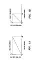
- FIG. 1A shows the general result of the flow calibration routine for the major material.
- FIG 1 B shows the result of the flow rate calibration for the minor material.
- FIG. 2 is a schematic representation of the dispensing apparatus of the instant invention.
- FIG. 3 is a flow chart of the pressure control loop of the instant invention.
- FIGS. 4A-4B is a flow chart showing the volume compensation scheme.
- the user sets the desired ratio, the maximum flow rate, and the number of volume updates per liter and the flow meter K factors (pulses/liter).
- Pressure loops are adjusted with Ki (integral) and Kp (proportional) gains independently for the major and minor materials. Pressure control of the two sides is performed on the basis of the pressure change between the outlet of the dispense valve and the inlet of the mixer.
- sources of major and minor components at relatively elevated pressures 12 and 14 respectively are connected to first and second flow meters 16 and 18 which are in turn connected to pressure regulators 20 and 22 , mixer 24 and dispense valve 26 .
- Gun calibration procedure is performed whereby major and minor materials are calibrated at the same time independently.
- the calibration routine provides the delta pressure required to obtain the maximum flow of the major and minor materials. In the example here the material requires a ratio of 2:1 of major to minor materials. The maximum total flow rate desired is 600 cc/minute.
- the calibration routine returns the delta pressure required to achieve 400 cc/minute of major volume and the delta pressure required to achieve 200 cc/minute of the minor volume.
- the pressure control is relatively straight forward as set forth in FIG. 3 .
- the updating of pressure and volume compensation occurs every 488 microseconds.
- the volume for partial pulses is calculated by interpolation when the actual volume integral is updated.
- the actual volume integral is decremented by the cc/pulse of the respective meter.
- the 1% referred to is 1% of the peak pressure resulting from the calibration routine.
- the robot looks to see if the flow is in the upper or lower half of the total range. If in the upper half of the range (typically greater than a 6 volt robot command) the upper peak pressure point is adjusted and if less than or equal to 6 volts, the zero offset value is adjusted. This discussion will only refer to the robot command being greater than 6 volts or in the upper half of the pressure range however as can be seen from the FIG. 4 flow chart, the logic is similar for adjustment in the lower end.
- the actual volume integral is updated on a periodic basis for both materials and a ratio error is then calculated.
- the controller looks to see if the flow is too low. If the flow is too low the controller looks to see if the error ratio is greater than zero, that is if there is too much major material and not enough minor material. If the error ratio is greater than zero, the peak pressure of A is increased by 1%. The controller then looks to see if the error ratio is greater than the previous error ratio. If it is, the peak pressure of A is increased by an additional 1%. However if it is not greater than the previous error ratio, that is, if it is coming back toward the desired ratio, the peak pressure of B is increased by 1%.
- ratio error is not greater than or equal to zero, that means there is too much minor component and not enough major and the peak pressure of B is increased by 1%.
- the system looks to see if the ratio error is less than the previous ratio error and if it is the peak pressure of B is increased by 1% and if not the peak pressure of A is increased by 1%.
- the system looks at the error ratio and if less than zero the peak pressure of A is decreased by 1%. The system then looks to see if the ratio error is less than the previous error and if it is the peak pressure of A is decremented by an additional 1% and if not, the peak pressure of B is decremented by 1%. Similarly, if the ratio error is not less than zero, the peak pressure of B is decremented by 1% and if the ratio error is greater than or equal to the previous error the peak pressure of B is decremented by an additional 1% and if not the peak pressure of A is decremented by 1%.
Landscapes
- Chemical & Material Sciences (AREA)
- Chemical Kinetics & Catalysis (AREA)
- Physics & Mathematics (AREA)
- General Physics & Mathematics (AREA)
- Engineering & Computer Science (AREA)
- Automation & Control Theory (AREA)
- Fluid Mechanics (AREA)
- Coating Apparatus (AREA)
- Application Of Or Painting With Fluid Materials (AREA)
- Feeding, Discharge, Calcimining, Fusing, And Gas-Generation Devices (AREA)
- Control Of Non-Electrical Variables (AREA)
- Flow Control (AREA)
Abstract
A dispensing apparatus (10) is capable of robotically dispensing plural component materials such as sealants and adhesives with the same precision as single component products and yet will maintain ratio assurance and integrity for mixing the two materials. First look at the flow rate and if the flow rate is too high, decrease is needed on one of the components. The ratio error is then looked at and the flow rate/pressure differential for the material which is there in excess is decremented. Another level of control is provided in that the ratio error is continually examined and the direction of the ratio error is used for additional control. This provides very precise control of ratio and flow and helps prevent oscillation, hunting and other undesirable characteristics in such a system.
Description
This application claims the benefit of Provisional Application No. 60/168,964, filed Dec. 3, 1999.
Devices for robotically dispensing sealants and adhesives on to parts have become increasingly popular in recent years.
Products such as Graco's PRECISIONFLO unit using technology such as shown in U.S. Pat. No. 5,847,285, the contents of which are incorporated by reference, have become increasingly popular with automotive manufacturers in order to provide precision application of a bead of (single component) adhesive for various applications. Such units typically dispense at pressures ranging from around 600 PSI to 3000 PSI. Recently, the material manufacturers of such sealants and adhesives have been producing plural component materials which provide increased performance for the manufacturer.
It is therefore an object of this invention to provide a dispensing apparatus which is capable of dispensing such plural component materials with the same precision as the single component products and yet will maintain ratio assurance and integrity for mixing the two materials.
Various parties involved in such manufacture use different terms for the materials involved. The major component of the plural material is also commonly referred to in the industry as the B component or the resin component. Similarly, the minor component is also often referred to as the A component, or activator, or catalyst.
Overall, the scheme can be characterized by saying first look at the flow rate. If the flow rate is too high, decrease is needed on one of the components so the ratio error is then looked at and the flow rate/pressure differential for the material which is there in excess is decremented. Another level of control is provided in that the ratio error is continually examined and the direction of the ratio error is used for additional control. This provides very precise control of ratio and flow and helps prevent oscillation, hunting and other undesirable characteristics in such a system.
These and other objects and advantages of the invention will appear more fully from the following description made in conjunction with the accompanying drawings wherein like reference characters refer to the same or similar parts throughout the several views.
FIG. 1A shows the general result of the flow calibration routine for the major material.
FIG 1B shows the result of the flow rate calibration for the minor material.
FIG. 2 is a schematic representation of the dispensing apparatus of the instant invention.
FIG. 3 is a flow chart of the pressure control loop of the instant invention.
FIGS. 4A-4B is a flow chart showing the volume compensation scheme.
In use, the user sets the desired ratio, the maximum flow rate, and the number of volume updates per liter and the flow meter K factors (pulses/liter). Pressure loops are adjusted with Ki (integral) and Kp (proportional) gains independently for the major and minor materials. Pressure control of the two sides is performed on the basis of the pressure change between the outlet of the dispense valve and the inlet of the mixer.
In the instant invention, generally designated 10, sources of major and minor components at relatively elevated pressures 12 and 14 respectively are connected to first and second flow meters 16 and 18 which are in turn connected to pressure regulators 20 and 22, mixer 24 and dispense valve 26.
Gun calibration procedure is performed whereby major and minor materials are calibrated at the same time independently. The calibration routine provides the delta pressure required to obtain the maximum flow of the major and minor materials. In the example here the material requires a ratio of 2:1 of major to minor materials. The maximum total flow rate desired is 600 cc/minute. The calibration routine returns the delta pressure required to achieve 400 cc/minute of major volume and the delta pressure required to achieve 200 cc/minute of the minor volume.
Referring to the drawing figures, circled letters are shown which refer to portions marked in the attached source code. The pressure control is relatively straight forward as set forth in FIG. 3. The updating of pressure and volume compensation occurs every 488 microseconds. First, the volume for partial pulses is calculated by interpolation when the actual volume integral is updated. During dispensing, each time a flow meter pulse is received, the actual volume integral is decremented by the cc/pulse of the respective meter.
As used herein the 1% referred to is 1% of the peak pressure resulting from the calibration routine. The robot then looks to see if the flow is in the upper or lower half of the total range. If in the upper half of the range (typically greater than a 6 volt robot command) the upper peak pressure point is adjusted and if less than or equal to 6 volts, the zero offset value is adjusted. This discussion will only refer to the robot command being greater than 6 volts or in the upper half of the pressure range however as can be seen from the FIG. 4 flow chart, the logic is similar for adjustment in the lower end.
As indicated, the actual volume integral is updated on a periodic basis for both materials and a ratio error is then calculated. Initially the controller looks to see if the flow is too low. If the flow is too low the controller looks to see if the error ratio is greater than zero, that is if there is too much major material and not enough minor material. If the error ratio is greater than zero, the peak pressure of A is increased by 1%. The controller then looks to see if the error ratio is greater than the previous error ratio. If it is, the peak pressure of A is increased by an additional 1%. However if it is not greater than the previous error ratio, that is, if it is coming back toward the desired ratio, the peak pressure of B is increased by 1%. If the ratio error is not greater than or equal to zero, that means there is too much minor component and not enough major and the peak pressure of B is increased by 1%. The system then looks to see if the ratio error is less than the previous ratio error and if it is the peak pressure of B is increased by 1% and if not the peak pressure of A is increased by 1%.
Similarly, it the flow is too high, the system looks at the error ratio and if less than zero the peak pressure of A is decreased by 1%. The system then looks to see if the ratio error is less than the previous error and if it is the peak pressure of A is decremented by an additional 1% and if not, the peak pressure of B is decremented by 1%. Similarly, if the ratio error is not less than zero, the peak pressure of B is decremented by 1% and if the ratio error is greater than or equal to the previous error the peak pressure of B is decremented by an additional 1% and if not the peak pressure of A is decremented by 1%.
It is contemplated that various changes and modifications may be made to the dispensing apparatus without departing from the spirit and scope of the invention as defined by the following claims.
Claims (2)
1. A method for dispensing plural component materials comprised of major and minor components at relatively elevated pressures at a predetermined flow rate, a predetermined maximum flow and at a predetermined ratio, the method comprising the steps of:
supplying said major and minor components at relatively elevated pressures;
measuring the amount of flow of each of said major and minor components during a relatively short period of time;
comparing the combined flow of said major and minor components during said period of time to said predetermined flow rate and if the measured flow rate is too high, examining the measured ratio and decrementing the flow for the material which is there in excess by a fixed percentage of said predetermined maximum flow; and
if the measured flow rate is too low, examining the measured ratio and incrementing the flow for the material which is insufficient by a fixed percentage of said predetermined maximum flow.
2. The method for dispensing plural component materials of claim 1 wherein the direction of change of ratio error formed by the difference between said predetermined ratio and said measured ratio is taken into account during correction.
Priority Applications (1)
| Application Number | Priority Date | Filing Date | Title |
|---|---|---|---|
| US10/130,863 US6824012B2 (en) | 1999-12-03 | 2000-12-01 | Plural component dispensing apparatus |
Applications Claiming Priority (4)
| Application Number | Priority Date | Filing Date | Title |
|---|---|---|---|
| US16896499P | 1999-12-03 | 1999-12-03 | |
| US60168964 | 1999-12-03 | ||
| PCT/US2000/032709 WO2001040737A1 (en) | 1999-12-03 | 2000-12-01 | Plural component dispensing apparatus |
| US10/130,863 US6824012B2 (en) | 1999-12-03 | 2000-12-01 | Plural component dispensing apparatus |
Publications (2)
| Publication Number | Publication Date |
|---|---|
| US20020170919A1 US20020170919A1 (en) | 2002-11-21 |
| US6824012B2 true US6824012B2 (en) | 2004-11-30 |
Family
ID=22613721
Family Applications (1)
| Application Number | Title | Priority Date | Filing Date |
|---|---|---|---|
| US10/130,863 Expired - Fee Related US6824012B2 (en) | 1999-12-03 | 2000-12-01 | Plural component dispensing apparatus |
Country Status (8)
| Country | Link |
|---|---|
| US (1) | US6824012B2 (en) |
| EP (1) | EP1257788B1 (en) |
| JP (1) | JP2003517666A (en) |
| KR (1) | KR20030022096A (en) |
| AU (1) | AU2056101A (en) |
| DE (1) | DE60030773T2 (en) |
| TW (1) | TW535042B (en) |
| WO (1) | WO2001040737A1 (en) |
Cited By (12)
| Publication number | Priority date | Publication date | Assignee | Title |
|---|---|---|---|---|
| US20050270899A1 (en) * | 2004-05-07 | 2005-12-08 | Oden Corporation | Continuous liquid stream blender |
| US7006896B1 (en) * | 1999-10-13 | 2006-02-28 | Graco Minnesota Inc. | Sealant dispensing correction method |
| US20060138170A1 (en) * | 2004-11-18 | 2006-06-29 | Eric Brim | Systems and methods for dispensing fluid |
| US20060278737A1 (en) * | 2005-06-09 | 2006-12-14 | Potter Industries Inc. | Highway marking sphere dispensing apparatus |
| US20070045445A1 (en) * | 2005-08-26 | 2007-03-01 | Joseph Hackel | Multi-component fluid spraying system |
| US20070260471A1 (en) * | 2006-05-02 | 2007-11-08 | Lincoln Industrial Corporation | Interface between dealer management system and fluid delivery system |
| US20080303691A1 (en) * | 2007-06-07 | 2008-12-11 | Lincoln Industrial Corporation | Hybrid automotive fluid dispensing system |
| US20140224835A1 (en) * | 2008-12-18 | 2014-08-14 | Sika Technology Ag | Dispensing tool for multi-component substances |
| US20200081458A1 (en) * | 2018-09-10 | 2020-03-12 | Michael D. Mitchell | Method of automatically controlling a volume of material dispensed in a constant pressure material dispensing system |
| US11144079B2 (en) | 2013-02-11 | 2021-10-12 | Graco Minnesota Inc. | Remote monitoring for fluid applicator system |
| US11213061B2 (en) * | 2019-08-23 | 2022-01-04 | Po-Chiao Tseng | Device for refilling vape solution |
| US11934210B2 (en) | 2013-02-11 | 2024-03-19 | Graco Minnesota Inc. | Paint sprayer distributed control and output volume monitoring architectures |
Families Citing this family (1)
| Publication number | Priority date | Publication date | Assignee | Title |
|---|---|---|---|---|
| FR3004365B1 (en) * | 2013-04-11 | 2015-05-15 | Cinetic Filling | DEVICE AND METHOD FOR CONTROLLED REMOVAL OF VISCOUS FLUID CORDS |
Citations (6)
| Publication number | Priority date | Publication date | Assignee | Title |
|---|---|---|---|---|
| US4341327A (en) * | 1980-02-28 | 1982-07-27 | Vernon Zeitz | Digital proportional metering pumping system |
| US5038971A (en) * | 1989-09-29 | 1991-08-13 | Tokheim Corporation | Variable blending dispenser |
| US5332125A (en) * | 1991-01-11 | 1994-07-26 | Nordson Corporation | Method & apparatus for metering flow of a two-component dispensing system |
| US5499745A (en) * | 1994-02-18 | 1996-03-19 | Nordson Corporation | Apparatus for mixing and dispensing two chemically reactive materials |
| US5857589A (en) * | 1996-11-20 | 1999-01-12 | Fluid Research Corporation | Method and apparatus for accurately dispensing liquids and solids |
| US5920829A (en) * | 1995-05-05 | 1999-07-06 | Nordson Corporation | Method of compensating for changes in flow characteristics of a dispensed fluid |
Family Cites Families (5)
| Publication number | Priority date | Publication date | Assignee | Title |
|---|---|---|---|---|
| JPS5415126B2 (en) * | 1974-04-23 | 1979-06-12 | ||
| JPH0458714U (en) * | 1990-09-26 | 1992-05-20 | ||
| JPH0512911U (en) * | 1991-02-27 | 1993-02-19 | 横河電機株式会社 | Raw material blending control device |
| JP2555250B2 (en) * | 1992-09-18 | 1996-11-20 | 株式会社中村金属工業所 | Continuous mixing device for sugar content adjustment |
| DE9415669U1 (en) * | 1994-09-28 | 1994-12-08 | Ramisch Kleinewefers Gmbh, 47803 Krefeld | Device for the proportional feeding of the components of a dye bath |
-
2000
- 2000-12-01 AU AU20561/01A patent/AU2056101A/en not_active Abandoned
- 2000-12-01 WO PCT/US2000/032709 patent/WO2001040737A1/en not_active Ceased
- 2000-12-01 JP JP2001542156A patent/JP2003517666A/en not_active Ceased
- 2000-12-01 DE DE60030773T patent/DE60030773T2/en not_active Expired - Lifetime
- 2000-12-01 KR KR1020027006913A patent/KR20030022096A/en not_active Ceased
- 2000-12-01 US US10/130,863 patent/US6824012B2/en not_active Expired - Fee Related
- 2000-12-01 EP EP00983854A patent/EP1257788B1/en not_active Expired - Lifetime
- 2000-12-02 TW TW089125705A patent/TW535042B/en not_active IP Right Cessation
Patent Citations (6)
| Publication number | Priority date | Publication date | Assignee | Title |
|---|---|---|---|---|
| US4341327A (en) * | 1980-02-28 | 1982-07-27 | Vernon Zeitz | Digital proportional metering pumping system |
| US5038971A (en) * | 1989-09-29 | 1991-08-13 | Tokheim Corporation | Variable blending dispenser |
| US5332125A (en) * | 1991-01-11 | 1994-07-26 | Nordson Corporation | Method & apparatus for metering flow of a two-component dispensing system |
| US5499745A (en) * | 1994-02-18 | 1996-03-19 | Nordson Corporation | Apparatus for mixing and dispensing two chemically reactive materials |
| US5920829A (en) * | 1995-05-05 | 1999-07-06 | Nordson Corporation | Method of compensating for changes in flow characteristics of a dispensed fluid |
| US5857589A (en) * | 1996-11-20 | 1999-01-12 | Fluid Research Corporation | Method and apparatus for accurately dispensing liquids and solids |
Cited By (26)
| Publication number | Priority date | Publication date | Assignee | Title |
|---|---|---|---|---|
| US7006896B1 (en) * | 1999-10-13 | 2006-02-28 | Graco Minnesota Inc. | Sealant dispensing correction method |
| US20050270899A1 (en) * | 2004-05-07 | 2005-12-08 | Oden Corporation | Continuous liquid stream blender |
| US7357563B2 (en) * | 2004-05-07 | 2008-04-15 | Oden Corporation | Continuous liquid stream blender |
| US20060138170A1 (en) * | 2004-11-18 | 2006-06-29 | Eric Brim | Systems and methods for dispensing fluid |
| US20060278737A1 (en) * | 2005-06-09 | 2006-12-14 | Potter Industries Inc. | Highway marking sphere dispensing apparatus |
| US7429146B2 (en) | 2005-06-09 | 2008-09-30 | Potters Industries, Inc. | Highway marking sphere dispensing apparatus |
| US20080310917A1 (en) * | 2005-06-09 | 2008-12-18 | Potters Industries, Inc | Highway marking sphere dispensing apparatus |
| US7654770B2 (en) | 2005-06-09 | 2010-02-02 | Potters Industries Inc. | Highway marking sphere dispensing apparatus |
| US20070045445A1 (en) * | 2005-08-26 | 2007-03-01 | Joseph Hackel | Multi-component fluid spraying system |
| US20070260471A1 (en) * | 2006-05-02 | 2007-11-08 | Lincoln Industrial Corporation | Interface between dealer management system and fluid delivery system |
| US20080303691A1 (en) * | 2007-06-07 | 2008-12-11 | Lincoln Industrial Corporation | Hybrid automotive fluid dispensing system |
| US20140224835A1 (en) * | 2008-12-18 | 2014-08-14 | Sika Technology Ag | Dispensing tool for multi-component substances |
| US11592850B2 (en) | 2013-02-11 | 2023-02-28 | Graco Minnesota Inc. | Remote monitoring for fluid applicator system |
| US11630470B2 (en) | 2013-02-11 | 2023-04-18 | Graco Inc. | Remote monitoring for fluid applicator system |
| US11144079B2 (en) | 2013-02-11 | 2021-10-12 | Graco Minnesota Inc. | Remote monitoring for fluid applicator system |
| US12339678B2 (en) | 2013-02-11 | 2025-06-24 | Graco Minnesota Inc. | Paint sprayer distributed control and output volume monitoring architectures |
| US11249498B2 (en) | 2013-02-11 | 2022-02-15 | Graco Minnesota Inc. | Remote monitoring for fluid applicator system |
| US11372432B2 (en) | 2013-02-11 | 2022-06-28 | Graco Minnesota Inc. | Remote monitoring for fluid applicator system |
| US12135568B2 (en) | 2013-02-11 | 2024-11-05 | Graco Minnesota Inc. | Remote monitoring for fluid applicator system |
| US11934211B2 (en) | 2013-02-11 | 2024-03-19 | Graco Minnesota Inc. | Paint sprayer distributed control and output volume monitoring architectures |
| US11698650B2 (en) | 2013-02-11 | 2023-07-11 | Graco Minnesota Inc. | Remote monitoring for fluid applicator system |
| US11934210B2 (en) | 2013-02-11 | 2024-03-19 | Graco Minnesota Inc. | Paint sprayer distributed control and output volume monitoring architectures |
| US11934212B2 (en) | 2013-02-11 | 2024-03-19 | Graco Minnesota Inc. | Paint sprayer distributed control and output volume monitoring architectures |
| US10976754B2 (en) * | 2018-09-10 | 2021-04-13 | Fca Us Llc | Method of automatically controlling a volume of material dispensed in a constant pressure material dispensing system |
| US20200081458A1 (en) * | 2018-09-10 | 2020-03-12 | Michael D. Mitchell | Method of automatically controlling a volume of material dispensed in a constant pressure material dispensing system |
| US11213061B2 (en) * | 2019-08-23 | 2022-01-04 | Po-Chiao Tseng | Device for refilling vape solution |
Also Published As
| Publication number | Publication date |
|---|---|
| EP1257788A4 (en) | 2005-07-20 |
| EP1257788A1 (en) | 2002-11-20 |
| KR20030022096A (en) | 2003-03-15 |
| US20020170919A1 (en) | 2002-11-21 |
| EP1257788B1 (en) | 2006-09-13 |
| WO2001040737A1 (en) | 2001-06-07 |
| JP2003517666A (en) | 2003-05-27 |
| TW535042B (en) | 2003-06-01 |
| DE60030773T2 (en) | 2007-11-08 |
| DE60030773D1 (en) | 2006-10-26 |
| AU2056101A (en) | 2001-06-12 |
Similar Documents
| Publication | Publication Date | Title |
|---|---|---|
| US6824012B2 (en) | Plural component dispensing apparatus | |
| CA2027384C (en) | Method and apparatus for controlling the gas content of foam materials | |
| JP3192286B2 (en) | Fluid metering method | |
| US6139903A (en) | Method of compensating for non-linear characteristics in dispensing a coating material | |
| US20050048195A1 (en) | Dispensing system and method of controlling the same | |
| JPH09117709A (en) | Fluid material discharge method | |
| EP3137229B1 (en) | Method for flow control calibration of high-transient systems | |
| US7934466B2 (en) | Coating plant and associated coating process | |
| KR20040074000A (en) | Process for Producing Polyurethane Moldings | |
| EP1464407A2 (en) | Multi-mode film coating apparatus and method | |
| JPS63111963A (en) | Coating agent feeder | |
| JP4006040B2 (en) | Flow rate fluctuation compensation method in fluid delivery system | |
| JP3117688U (en) | Two-component paint coating equipment | |
| JPH08266878A (en) | Liquid continuous mixing device | |
| JPH02199281A (en) | Pressure variation type delivery amount stabilizing dispense control device for quantitative delivery device | |
| JPH05104050A (en) | Device for controlling flow rate of high viscosity material | |
| JPH0357834B2 (en) | ||
| KR100467184B1 (en) | Volume compensating pressure regulated flow control dispensing system | |
| Hale | Methods of Powder Delivery Control for Porcelain Enamel | |
| JPH04200773A (en) | Method for controlling emitting amount of paint in painting apparatus | |
| JPS5864509A (en) | Method and device for controlling flow rate of liquid | |
| JPS6142370A (en) | Quantitative supply of two-part paint | |
| JPH08117655A (en) | Coating apparatus | |
| JPS61174966A (en) | Process and device for coating inside of pipe |
Legal Events
| Date | Code | Title | Description |
|---|---|---|---|
| AS | Assignment |
Owner name: GRACO MINNESOTA INC., MINNESOTA Free format text: ASSIGNMENT OF ASSIGNORS INTEREST;ASSIGNOR:WERNER, NEAL A.;REEL/FRAME:013124/0107 Effective date: 20020520 |
|
| FPAY | Fee payment |
Year of fee payment: 4 |
|
| REMI | Maintenance fee reminder mailed | ||
| LAPS | Lapse for failure to pay maintenance fees | ||
| STCH | Information on status: patent discontinuation |
Free format text: PATENT EXPIRED DUE TO NONPAYMENT OF MAINTENANCE FEES UNDER 37 CFR 1.362 |
|
| FP | Lapsed due to failure to pay maintenance fee |
Effective date: 20121130 |