US6821654B1 - CrMoTa underlayer - Google Patents
CrMoTa underlayer Download PDFInfo
- Publication number
- US6821654B1 US6821654B1 US10/269,872 US26987202A US6821654B1 US 6821654 B1 US6821654 B1 US 6821654B1 US 26987202 A US26987202 A US 26987202A US 6821654 B1 US6821654 B1 US 6821654B1
- Authority
- US
- United States
- Prior art keywords
- magnetic
- layer
- magnetic recording
- recording medium
- medium according
- Prior art date
- Legal status (The legal status is an assumption and is not a legal conclusion. Google has not performed a legal analysis and makes no representation as to the accuracy of the status listed.)
- Expired - Fee Related
Links
Images


Classifications
-
- G—PHYSICS
- G11—INFORMATION STORAGE
- G11B—INFORMATION STORAGE BASED ON RELATIVE MOVEMENT BETWEEN RECORD CARRIER AND TRANSDUCER
- G11B5/00—Recording by magnetisation or demagnetisation of a record carrier; Reproducing by magnetic means; Record carriers therefor
- G11B5/62—Record carriers characterised by the selection of the material
- G11B5/64—Record carriers characterised by the selection of the material comprising only the magnetic material without bonding agent
- G11B5/66—Record carriers characterised by the selection of the material comprising only the magnetic material without bonding agent the record carriers consisting of several layers
- G11B5/676—Record carriers characterised by the selection of the material comprising only the magnetic material without bonding agent the record carriers consisting of several layers having magnetic layers separated by a nonmagnetic layer, e.g. antiferromagnetic layer, Cu layer or coupling layer
-
- G—PHYSICS
- G11—INFORMATION STORAGE
- G11B—INFORMATION STORAGE BASED ON RELATIVE MOVEMENT BETWEEN RECORD CARRIER AND TRANSDUCER
- G11B5/00—Recording by magnetisation or demagnetisation of a record carrier; Reproducing by magnetic means; Record carriers therefor
- G11B5/62—Record carriers characterised by the selection of the material
- G11B5/73—Base layers, i.e. all non-magnetic layers lying under a lowermost magnetic recording layer, e.g. including any non-magnetic layer in between a first magnetic recording layer and either an underlying substrate or a soft magnetic underlayer
- G11B5/7368—Non-polymeric layer under the lowermost magnetic recording layer
- G11B5/7369—Two or more non-magnetic underlayers, e.g. seed layers or barrier layers
-
- G—PHYSICS
- G11—INFORMATION STORAGE
- G11B—INFORMATION STORAGE BASED ON RELATIVE MOVEMENT BETWEEN RECORD CARRIER AND TRANSDUCER
- G11B5/00—Recording by magnetisation or demagnetisation of a record carrier; Reproducing by magnetic means; Record carriers therefor
- G11B5/62—Record carriers characterised by the selection of the material
- G11B5/73—Base layers, i.e. all non-magnetic layers lying under a lowermost magnetic recording layer, e.g. including any non-magnetic layer in between a first magnetic recording layer and either an underlying substrate or a soft magnetic underlayer
- G11B5/7368—Non-polymeric layer under the lowermost magnetic recording layer
- G11B5/7373—Non-magnetic single underlayer comprising chromium
-
- Y—GENERAL TAGGING OF NEW TECHNOLOGICAL DEVELOPMENTS; GENERAL TAGGING OF CROSS-SECTIONAL TECHNOLOGIES SPANNING OVER SEVERAL SECTIONS OF THE IPC; TECHNICAL SUBJECTS COVERED BY FORMER USPC CROSS-REFERENCE ART COLLECTIONS [XRACs] AND DIGESTS
- Y10—TECHNICAL SUBJECTS COVERED BY FORMER USPC
- Y10S—TECHNICAL SUBJECTS COVERED BY FORMER USPC CROSS-REFERENCE ART COLLECTIONS [XRACs] AND DIGESTS
- Y10S428/00—Stock material or miscellaneous articles
- Y10S428/90—Magnetic feature
Definitions
- the present invention relates to magnetic recording media, such as thin film magnetic recording disks.
- the present invention has particular applicability to high areal density longitudinal magnetic recording media exhibiting low noise and enhanced magnetic performance.
- Magnetic recording media are extensively employed in the computer industry and can be locally magnetized by a write transducer or write head to record and store information.
- the write transducer creates a highly concentrated magnetic field which alternates direction based upon bits of the information being stored.
- grains of the recording medium at that location are magnetized. The grains retain their magnetization after the magnetic field produced by the write transducer is removed.
- the direction of the magnetization matches the direction of the applied magnetic field.
- the magnetization of the recording medium can subsequently produce an electrical response to a read sensor, allowing the stored information to be read.
- the linear recording density can be increased by increasing the Hc of the magnetic recording medium, and can be accomplished by decreasing the medium noise, as by maintaining very fine magnetically non-coupled grains.
- Medium noise in thin films is a dominant factor restricting increased recording density of high density magnetic hard disk drives, and is attributed primarily to inhomogeneous and large grain size and intergranular exchange coupling. Accordingly, in order to increase linear density, medium noise must be minimized by suitable microstructure control.
- Longitudinal magnetic recording media containing cobalt (Co) or Co-based alloy magnetic films with a chromium (Cr) or Cr alloy underlayer deposited on a non-magnetic substrate have become the industry standard.
- the desired crystallized structure of the Co and Co alloys is hexagonal close packed (HCP) with uniaxial crystalline anisotropy and a magnetization easy direction along the c-axis is in the plane of the film.
- HCP hexagonal close packed
- coercivity increases with increased grain size. The large grains, however, result in greater noise.
- the Co alloy thin film should have uniform small grains with grain boundaries capable of magnetically isolating neighboring grains. This type of microstructural and crystallographic control is typically attempted by manipulating the deposition process, grooving the substrate surface and proper use of an underlayer.
- An advantage of the present invention is a magnetic recording medium for high areal recording density exhibiting low noise and high coercivity, with a magnetic layer or layers exhibiting a highly uniform grain size.
- a magnetic recording medium comprising: a chromium-molybdenum-tantalum (CrMoTa) underlayer; and a magnetic layer over the underlayer, the magnetic layer having a uniform grain size with a standard deviation less than 0.4.
- CrMoTa chromium-molybdenum-tantalum
- Embodiments of the present invention comprise a composite underlayer system containing a first Cr layer, e.g., elemental chromium, and a Cr 100-x-y Mo x Ta y layer thereon, wherein x is 1 to 12, e.g., 8 to 12, and y is 1 to 6, e.g., 2 to 4.
- Embodiments of the present invention further include magnetic recording media comprising a non-magnetic substrate, a seedlayer on the substrate, a Cr underlayer on the seedlayer, a CrMoTa underlayer on the Cr underlayer, an interlayer on the CrMoTa underlayer and a magnetic layer on the interlayer.
- Embodiments of the present invention further include anti-ferromagnetically coupled ferromagnetic films with a spacer layer, with or without an interface layer on one or both sides of the spacer layer positioned between the ferromagnetic layers.
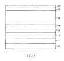
- FIG. 1 schematically illustrates a magnetic recording medium in accordance with an embodiment of the present invention.
- FIG. 2 schematically illustrates a magnetic recording medium in accordance with another embodiment of the present invention.
- FIGS. 3A and 3B graphically illustrate the improved in grain size uniformity distribution of the present invention vis-à-vis a conventional underlayer structure.
- FIG. 4 represents X-ray defraction measurements illustrating in-plane orientation of the c axis in the inventive media.
- FIGS. 1 and 2 similar elements are denoted by similar reference characters.
- the present invention provides high areal recording density longitudinal magnetic recording media exhibiting high SNR and high coercivity.
- the present invention achieves such technological advantages by strategically formulating an underlayer structure of CrMoTa to significantly improve the uniformity of grains in the magnetic layer or layers and to achieve superior in-plane orientation of magnetic grains, thereby resulting in a significant improvement in SNR, e.g., of about 0.6 dB, and an improvement in bit error rate.
- Embodiments of the present invention comprise the use of a Cr 100-x-y Mo x Ta y underlayer wherein x is 1to 20 and y is 1 to 6.
- Advantageous results have been achieved wherein x is 2 to 4, e.g., 3, and y is 8 to 12, e.g., 10.
- Conventional magnetic recording media are characterized by a magnetic layer with a grain size lacking the requisite uniformity to achieve high SNR.
- conventional magnetic recording media typically comprise magnetic layers having a grain size with a standard deviation of about 0.7 or 0.8, as for a grain size of 9 nm.
- the strategic use of a CrMoTa underlayer in accordance with embodiments of the present invention achieves an improvement in grain size uniformity over conventional magnetic recording media of greater than 50% without compromising crystallographic orientation.
- Embodiments of the present invention comprise magnetic recording media with a magnetic layer or layers having a grain size uniformity less than 0.4, e.g., less than 0.3.
- the present invention is applicable to magnetic recording media having one or more ferromagnetic layers, e.g., ferromagnetic alloys of cobalt-chromium (CoCr), or alloys of CoCr with one or more elements such as platinum (Pt), tantalum (Ta), boron (B), molybdenum (Mo), ruthenium (Ru), silicon (Si), germanium (Ge), niobium (Nb), iron (Fe) and nickel (Ni).
- the magnetic layer comprises anti-ferromagnetically coupled ferromagnetic films with a spacer layer therebetween, with or without an interface layer on one or both sides of the spacer layer.
- Such ferromagnetic layers can comprise CoCr or an alloy of CoCr with one or more added elements, such as Pt, Ta, B, Mo, Ru, Si, Ge, Nb, Fe and Ni.
- the ferromagnetic layers can comprise the same alloy, and are typically spaced apart by a spacer layer consisting of a non-magnetic material, such as Ru, rhodium (Rh), iridium (Ir), Cr, copper (Cu), rhenium (Re), vanadium (V) and their alloys.
- the interface layers which can be positioned on one or both sides of the spacer layer between the spacer layer and the ferromagnetic layers, typically have a large magnetic moment, with an Ms greater than 400 emu/cc, and typically consist of high moment elements, such as Fe, Co or their alloys with one or more elements such as Cr, Pt, Ta, B, Mo, Ru, Si, Ge, Nb and Ni.
- Magnetic layers deposited in accordance with embodiments of the present invention typically have a thickness of about 90 ⁇ to 100 ⁇ .
- the anti-ferromagnetically coupled embodiments of the present invention typically have a total magnetic layer thickness of 150 ⁇ to 200 ⁇ .
- Embodiments of the present invention comprise a conventional non-magnetic substrate, such as an aluminum-magnesium alloy, or a glass, glass-ceramic or ceramic substrate. A sequence of layers is then provided on both sides of the substrate in a conventional manner, as by sputter deposition.
- a non-magnetic seedlayer such as amorphous nickel-phosphorous or CrTa or a fine grained material such as nickel-aluminum (NiAl) or chromium-titanium (CrTi) is then formed on the substrate, as at a thickness of 10 ⁇ to 200 ⁇ .
- a first underlayer is then formed on the seedlayer, such as elemental chromium, at the thickness of 30 ⁇ to 80 ⁇ .
- the CrMoTa underlayer is then deposited thickness of 30 ⁇ to 80 ⁇ .
- An interlayer is then formed on the CrMoTa underlayer, as at a thickness of 10 ⁇ to 20 ⁇ .
- the interlayer can comprise a non-magnetic or magnetic alloy, such as CoCr, or CoCr with one or more added elements, such as Pt, B, Ta and Ru.
- a magnetic layer is then formed on the interlayer.
- a protective overcoat such as a carbon-containing protective overcoat, is then formed on the magnetic layer, and a lubricant topcoat formed on the protective overcoat.
- a magnetic recording medium in accordance with an embodiment of the present invention is schematically illustrated in FIG. 1 and comprises substrate 10 , seedlayer 11 formed thereon, Cr underlayer 12 and CrMoTa underlayer 13 which serves to refine the grain size and maintain uniformity in the subsequently deposited magnetic layer 15 after depositing interlayer 14 .
- Underlayer 13 can be represented by the formula Cr 100-x-y Mo x Ta y , wherein x is 1 to 20 and y is 1 to 6, such as x is 8 to 12 and y is 2 to 4, e.g., x is 10 and y is 3.
- Carbon-containing protective overcoat 16 and lubricant topcoat 17 are then deposited. It should be understood that layers 11 through 17 are sequentially deposited on both sides of the substrate 10 .
- magnetic recording media in accordance with the present invention can be manufactured using an in-line, pass-by sputtering system wherein layers are sequentially sputtered deposited on the substrate.
- FIG. 2 Another embodiment of the present invention is schematically illustrated in FIG. 2 and contains layers 11 through 14 , 16 and 17 corresponding to those of magnetic recording medium depicted in FIG. 1 .
- the magnetic recording illustrated in FIG. 2 differs from that illustrated in FIG. 1 in that the magnetic layer comprises anti-ferromagnetically coupled ferromagnetic layers 20 A and 20 B separated by a spacer layer 21 with interface layers 22 A and 22 B between the spacer layer 21 and first and second ferromagnetic layers 20 A and 20 B.
- FIGS. 3A and 3B compare grain size distributions for two anti-ferromagnetically coupled recording media designs.
- the magnetic recording medium of FIG. 3A was manufactured with a Cr/CrW underlayer structure; whereas, the magnetic recording media of FIG. 3B was fabricated with a Cr/CrMoTa underlayer structure.
- the medium with the Cr/CrMoTa underlayer structure in accordance with the present invention exhibited a more uniform grain size distribution.
- Measurements reveal that the Cr/Cr 90 W 10 interlayer/AFC structure of the FIG. 3A medium had a mean grain size of 8.07 nm with a standard deviation of 0.86.
- the Cr/Cr 87 Mo 10 Ta 3 /interlayer/AFC structure of the FIG. 3B medium in accordance with an embodiment of the present invention had a mean grain size of 8.00 nm, with a standard deviation of 0.39.
- X-ray diffraction measurements which reveal a significant increase of (11-20) diffraction peaks in media with an CrCr 87 Mo 10 Ta 3 underlayer structure, which is indicative of superior in-plane orientation of the c-axis vis-à-vis the medium with the Cr/Cr 90 /W 10 underlayer structure.
- the XRD measurements are shown in FIG. 4 .
- the strategic use of a CrMoTa underlayer structure in accordance with embodiments of the present invention enables a significant improvement in grain size uniformity of the magnetic layer or layers and superior in-plane orientation of magnetic grains resulting in an increase in SNR and improvement in bit error rate.
- the present invention enjoys industrial applicability in manufacturing various types of high areal density longitudinal recording media exhibiting low noise and improve magnetic properties, including anti-ferromagnetically coupled type media.
- Magnetic recording media in accordance with the present invention are not limited to any particular substrate material, seedlayer, interlayer, magnetic layers, protective overcoats or lubricant topcoats.
Landscapes
- Magnetic Record Carriers (AREA)
Abstract
Description
| TABLE 1 | ||||||||||||
| LF | MF | Read | Write | OTC | PE | eSNR | Elec eSNR | Media eSNR | ||||
| AMP | AMP | ASYM | Ovw | PW50 | Width | Width | Err | Err | Time | Freq | Time | Freq | Time | Freq | eSDR |
| (mV,0-p) | (%) | (dB) | (uin) | (uin) | (uin) | Floor | Floor | (dB) | (dB) | (dB) | (dB) | ||
| Cr/Cr90W10/ | 578 | 403 | 2 | 29.4 | 4.10 | 4.63 | 7.60 | −5.57 | −6.38 | 13.61 | 14.24 | 19.42 | 18.70 | 14.94 | 16.17 | 22.71 |
| 611 | 436 | 2 | 29.0 | 4.04 | 4.65 | 7.47 | −5.73 | −6.35 | 13.56 | 14.25 | 19.82 | 19.37 | 14.74 | 15.85 | 22.85 | |
| 595 | 420 | 2 | 29.2 | 4.07 | 4.64 | 7.53 | −5.65 | −6.36 | 13.6 | 14.2 | 19.6 | 19.0 | 14.8 | 16.0 | 22.8 | |
| Cr/Cr87Mo10Ta3/ | 577 | 425 | 2 | 31.0 | 3.94 | 4.60 | 7.42 | −6.12 | −6.69 | 14.06 | 14.65 | 20.29 | 19.75 | 15.25 | 16.26 | 23.38 |
| 624 | 432 | 1 | 30.5 | 4.01 | 4.69 | 7.66 | −6.18 | −6.82 | 14.13 | 14.58 | 20.14 | 19.78 | 15.38 | 16.14 | 23.41 | |
| 600 | 428 | 2 | 30.7 | 3.97 | 4.64 | 7.54 | −6.15 | −6.75 | 14.1 | 14.6 | 20.2 | 19.8 | 15.3 | 16.2 | 23.4 | |
Claims (19)
Priority Applications (1)
| Application Number | Priority Date | Filing Date | Title |
|---|---|---|---|
| US10/269,872 US6821654B1 (en) | 2002-06-12 | 2002-10-15 | CrMoTa underlayer |
Applications Claiming Priority (2)
| Application Number | Priority Date | Filing Date | Title |
|---|---|---|---|
| US38840302P | 2002-06-12 | 2002-06-12 | |
| US10/269,872 US6821654B1 (en) | 2002-06-12 | 2002-10-15 | CrMoTa underlayer |
Publications (1)
| Publication Number | Publication Date |
|---|---|
| US6821654B1 true US6821654B1 (en) | 2004-11-23 |
Family
ID=33436628
Family Applications (1)
| Application Number | Title | Priority Date | Filing Date |
|---|---|---|---|
| US10/269,872 Expired - Fee Related US6821654B1 (en) | 2002-06-12 | 2002-10-15 | CrMoTa underlayer |
Country Status (1)
| Country | Link |
|---|---|
| US (1) | US6821654B1 (en) |
Cited By (2)
| Publication number | Priority date | Publication date | Assignee | Title |
|---|---|---|---|---|
| US20070122660A1 (en) * | 2005-11-28 | 2007-05-31 | Seagate Technology Llc | Magnetic recording media with manganese-containing underlayer |
| CN108613998A (en) * | 2018-05-30 | 2018-10-02 | 广州兴森快捷电路科技有限公司 | The evaluation method and evaluation system of grain uniformity applied to pcb board |
Citations (3)
| Publication number | Priority date | Publication date | Assignee | Title |
|---|---|---|---|---|
| US6280813B1 (en) * | 1999-10-08 | 2001-08-28 | International Business Machines Corporation | Magnetic recording media with antiferromagnetically coupled ferromagnetic films as the recording layer |
| US6287429B1 (en) * | 1992-10-26 | 2001-09-11 | Hoya Corporation | Magnetic recording medium having an improved magnetic characteristic |
| US6613460B1 (en) * | 1999-11-12 | 2003-09-02 | Fujitsu Limited | Magnetic recording medium and magnetic storage apparatus |
-
2002
- 2002-10-15 US US10/269,872 patent/US6821654B1/en not_active Expired - Fee Related
Patent Citations (3)
| Publication number | Priority date | Publication date | Assignee | Title |
|---|---|---|---|---|
| US6287429B1 (en) * | 1992-10-26 | 2001-09-11 | Hoya Corporation | Magnetic recording medium having an improved magnetic characteristic |
| US6280813B1 (en) * | 1999-10-08 | 2001-08-28 | International Business Machines Corporation | Magnetic recording media with antiferromagnetically coupled ferromagnetic films as the recording layer |
| US6613460B1 (en) * | 1999-11-12 | 2003-09-02 | Fujitsu Limited | Magnetic recording medium and magnetic storage apparatus |
Cited By (3)
| Publication number | Priority date | Publication date | Assignee | Title |
|---|---|---|---|---|
| US20070122660A1 (en) * | 2005-11-28 | 2007-05-31 | Seagate Technology Llc | Magnetic recording media with manganese-containing underlayer |
| CN108613998A (en) * | 2018-05-30 | 2018-10-02 | 广州兴森快捷电路科技有限公司 | The evaluation method and evaluation system of grain uniformity applied to pcb board |
| CN108613998B (en) * | 2018-05-30 | 2020-11-17 | 广州兴森快捷电路科技有限公司 | Evaluation method and evaluation system for uniformity of crystal grains of PCB |
Similar Documents
| Publication | Publication Date | Title |
|---|---|---|
| US8685547B2 (en) | Magnetic recording media with enhanced writability and thermal stability | |
| US6620531B1 (en) | Magnetic recording media with oxidized seedlayer for reduced grain size and reduced grain size distribution | |
| US7431999B2 (en) | Perpendicular magnetic recording medium and magnetic recording/reproducing apparatus | |
| US20100119878A1 (en) | Magnetic recording medium | |
| CN101162587B (en) | Perpendicular magnetic recording medium | |
| EP1686571A1 (en) | Perpendicular magnetic recording medium and disk | |
| US20010018136A1 (en) | High anisotropy alloy for thin film disk | |
| US7871718B2 (en) | Perpendicular magnetic recording medium and magnetic storage apparatus | |
| US6010795A (en) | Magnetic recording medium comprising a nickel aluminum or iron aluminum underlayer and chromium containing intermediate layer each having (200) dominant crystalographic orientation | |
| US7993764B2 (en) | Perpendicular magnetic recording medium and the method of manufacturing the same | |
| US6221481B1 (en) | High Cr, low saturation magnetization intermediate magnetic layer for high coercivity and low medium noise | |
| US20020018920A1 (en) | Magnetic recording medium and magnetic recording apparatus | |
| EP1801790A1 (en) | Perpendicular magnetic recording disk with ultrathin nucleation film and method for making the disk | |
| EP1755113A1 (en) | Perpendicular magnetic recording disk with recording layer containing selected metal oxides and formed on a reduced-thickness exchange-break layer | |
| US6593009B2 (en) | Magnetic thin film media with a pre-seed layer of CrTi | |
| JP2007317304A (en) | Magnetic recording medium and magnetic storage device | |
| US6432562B1 (en) | Magnetic recording medium with a nialru seedlayer | |
| US20100079911A1 (en) | Magnetic recording medium, process for producing same, and magnetic recording reproducing apparatus using the magnetic recording medium | |
| US6461750B1 (en) | Magnetic recording medium with dual magnetic layers and high in-plane coercivity | |
| US6872478B2 (en) | Magnetic thin film media with a pre-seed layer of CrTiAl | |
| US6689497B1 (en) | Stabilized AFC magnetic recording media with reduced lattice mismatch between spacer layer(s) and magnetic layers | |
| US6168861B1 (en) | High coercivity, high signal-to-noise ratio dual magnetic layer media | |
| US6346339B1 (en) | Magnetic recording media with a nialox sub-seedlayer | |
| US6348276B1 (en) | Magnetic recording media with a surface-oxidized nial sub-seedlayer | |
| US7427446B2 (en) | Magnetic recording medium with antiparallel magnetic layers and CrN based underlayer, magnetic storage apparatus and method of producing magnetic recording medium |
Legal Events
| Date | Code | Title | Description |
|---|---|---|---|
| AS | Assignment |
Owner name: SEAGATE TECHNOLOGY, LLC, CALIFORNIA Free format text: ASSIGNMENT OF ASSIGNORS INTEREST;ASSIGNOR:MUNTEANU, MARIANA RODICA;REEL/FRAME:013410/0125 Effective date: 20021007 |
|
| FPAY | Fee payment |
Year of fee payment: 4 |
|
| AS | Assignment |
Owner name: WELLS FARGO BANK, NATIONAL ASSOCIATION, AS COLLATERAL AGENT AND SECOND PRIORITY REPRESENTATIVE, CALIFORNIA Free format text: SECURITY AGREEMENT;ASSIGNORS:MAXTOR CORPORATION;SEAGATE TECHNOLOGY LLC;SEAGATE TECHNOLOGY INTERNATIONAL;REEL/FRAME:022757/0017 Effective date: 20090507 Owner name: JPMORGAN CHASE BANK, N.A., AS ADMINISTRATIVE AGENT AND FIRST PRIORITY REPRESENTATIVE, NEW YORK Free format text: SECURITY AGREEMENT;ASSIGNORS:MAXTOR CORPORATION;SEAGATE TECHNOLOGY LLC;SEAGATE TECHNOLOGY INTERNATIONAL;REEL/FRAME:022757/0017 Effective date: 20090507 Owner name: JPMORGAN CHASE BANK, N.A., AS ADMINISTRATIVE AGENT Free format text: SECURITY AGREEMENT;ASSIGNORS:MAXTOR CORPORATION;SEAGATE TECHNOLOGY LLC;SEAGATE TECHNOLOGY INTERNATIONAL;REEL/FRAME:022757/0017 Effective date: 20090507 Owner name: WELLS FARGO BANK, NATIONAL ASSOCIATION, AS COLLATE Free format text: SECURITY AGREEMENT;ASSIGNORS:MAXTOR CORPORATION;SEAGATE TECHNOLOGY LLC;SEAGATE TECHNOLOGY INTERNATIONAL;REEL/FRAME:022757/0017 Effective date: 20090507 |
|
| AS | Assignment |
Owner name: SEAGATE TECHNOLOGY HDD HOLDINGS, CALIFORNIA Free format text: RELEASE;ASSIGNOR:JPMORGAN CHASE BANK, N.A., AS ADMINISTRATIVE AGENT;REEL/FRAME:025662/0001 Effective date: 20110114 Owner name: SEAGATE TECHNOLOGY INTERNATIONAL, CALIFORNIA Free format text: RELEASE;ASSIGNOR:JPMORGAN CHASE BANK, N.A., AS ADMINISTRATIVE AGENT;REEL/FRAME:025662/0001 Effective date: 20110114 Owner name: SEAGATE TECHNOLOGY LLC, CALIFORNIA Free format text: RELEASE;ASSIGNOR:JPMORGAN CHASE BANK, N.A., AS ADMINISTRATIVE AGENT;REEL/FRAME:025662/0001 Effective date: 20110114 Owner name: MAXTOR CORPORATION, CALIFORNIA Free format text: RELEASE;ASSIGNOR:JPMORGAN CHASE BANK, N.A., AS ADMINISTRATIVE AGENT;REEL/FRAME:025662/0001 Effective date: 20110114 |
|
| AS | Assignment |
Owner name: THE BANK OF NOVA SCOTIA, AS ADMINISTRATIVE AGENT, CANADA Free format text: SECURITY AGREEMENT;ASSIGNOR:SEAGATE TECHNOLOGY LLC;REEL/FRAME:026010/0350 Effective date: 20110118 Owner name: THE BANK OF NOVA SCOTIA, AS ADMINISTRATIVE AGENT, Free format text: SECURITY AGREEMENT;ASSIGNOR:SEAGATE TECHNOLOGY LLC;REEL/FRAME:026010/0350 Effective date: 20110118 |
|
| FPAY | Fee payment |
Year of fee payment: 8 |
|
| AS | Assignment |
Owner name: SEAGATE TECHNOLOGY US HOLDINGS, INC., CALIFORNIA Free format text: TERMINATION AND RELEASE OF SECURITY INTEREST IN PATENT RIGHTS;ASSIGNOR:WELLS FARGO BANK, NATIONAL ASSOCIATION, AS COLLATERAL AGENT AND SECOND PRIORITY REPRESENTATIVE;REEL/FRAME:030833/0001 Effective date: 20130312 Owner name: EVAULT INC. (F/K/A I365 INC.), CALIFORNIA Free format text: TERMINATION AND RELEASE OF SECURITY INTEREST IN PATENT RIGHTS;ASSIGNOR:WELLS FARGO BANK, NATIONAL ASSOCIATION, AS COLLATERAL AGENT AND SECOND PRIORITY REPRESENTATIVE;REEL/FRAME:030833/0001 Effective date: 20130312 Owner name: SEAGATE TECHNOLOGY INTERNATIONAL, CAYMAN ISLANDS Free format text: TERMINATION AND RELEASE OF SECURITY INTEREST IN PATENT RIGHTS;ASSIGNOR:WELLS FARGO BANK, NATIONAL ASSOCIATION, AS COLLATERAL AGENT AND SECOND PRIORITY REPRESENTATIVE;REEL/FRAME:030833/0001 Effective date: 20130312 Owner name: SEAGATE TECHNOLOGY LLC, CALIFORNIA Free format text: TERMINATION AND RELEASE OF SECURITY INTEREST IN PATENT RIGHTS;ASSIGNOR:WELLS FARGO BANK, NATIONAL ASSOCIATION, AS COLLATERAL AGENT AND SECOND PRIORITY REPRESENTATIVE;REEL/FRAME:030833/0001 Effective date: 20130312 |
|
| REMI | Maintenance fee reminder mailed | ||
| LAPS | Lapse for failure to pay maintenance fees | ||
| STCH | Information on status: patent discontinuation |
Free format text: PATENT EXPIRED DUE TO NONPAYMENT OF MAINTENANCE FEES UNDER 37 CFR 1.362 |
|
| STCH | Information on status: patent discontinuation |
Free format text: PATENT EXPIRED DUE TO NONPAYMENT OF MAINTENANCE FEES UNDER 37 CFR 1.362 |
|
| FP | Lapsed due to failure to pay maintenance fee |
Effective date: 20161123 |
|
| AS | Assignment |
Owner name: SEAGATE TECHNOLOGY PUBLIC LIMITED COMPANY, CALIFORNIA Free format text: RELEASE BY SECURED PARTY;ASSIGNOR:THE BANK OF NOVA SCOTIA;REEL/FRAME:072193/0001 Effective date: 20250303 Owner name: SEAGATE TECHNOLOGY, CALIFORNIA Free format text: RELEASE BY SECURED PARTY;ASSIGNOR:THE BANK OF NOVA SCOTIA;REEL/FRAME:072193/0001 Effective date: 20250303 Owner name: SEAGATE TECHNOLOGY HDD HOLDINGS, CALIFORNIA Free format text: RELEASE BY SECURED PARTY;ASSIGNOR:THE BANK OF NOVA SCOTIA;REEL/FRAME:072193/0001 Effective date: 20250303 Owner name: I365 INC., CALIFORNIA Free format text: RELEASE BY SECURED PARTY;ASSIGNOR:THE BANK OF NOVA SCOTIA;REEL/FRAME:072193/0001 Effective date: 20250303 Owner name: SEAGATE TECHNOLOGY LLC, CALIFORNIA Free format text: RELEASE BY SECURED PARTY;ASSIGNOR:THE BANK OF NOVA SCOTIA;REEL/FRAME:072193/0001 Effective date: 20250303 Owner name: SEAGATE TECHNOLOGY INTERNATIONAL, CAYMAN ISLANDS Free format text: RELEASE BY SECURED PARTY;ASSIGNOR:THE BANK OF NOVA SCOTIA;REEL/FRAME:072193/0001 Effective date: 20250303 Owner name: SEAGATE HDD CAYMAN, CAYMAN ISLANDS Free format text: RELEASE BY SECURED PARTY;ASSIGNOR:THE BANK OF NOVA SCOTIA;REEL/FRAME:072193/0001 Effective date: 20250303 Owner name: SEAGATE TECHNOLOGY (US) HOLDINGS, INC., CALIFORNIA Free format text: RELEASE BY SECURED PARTY;ASSIGNOR:THE BANK OF NOVA SCOTIA;REEL/FRAME:072193/0001 Effective date: 20250303 Owner name: SEAGATE TECHNOLOGY PUBLIC LIMITED COMPANY, CALIFORNIA Free format text: RELEASE OF SECURITY INTEREST;ASSIGNOR:THE BANK OF NOVA SCOTIA;REEL/FRAME:072193/0001 Effective date: 20250303 Owner name: SEAGATE TECHNOLOGY, CALIFORNIA Free format text: RELEASE OF SECURITY INTEREST;ASSIGNOR:THE BANK OF NOVA SCOTIA;REEL/FRAME:072193/0001 Effective date: 20250303 Owner name: SEAGATE TECHNOLOGY HDD HOLDINGS, CALIFORNIA Free format text: RELEASE OF SECURITY INTEREST;ASSIGNOR:THE BANK OF NOVA SCOTIA;REEL/FRAME:072193/0001 Effective date: 20250303 Owner name: I365 INC., CALIFORNIA Free format text: RELEASE OF SECURITY INTEREST;ASSIGNOR:THE BANK OF NOVA SCOTIA;REEL/FRAME:072193/0001 Effective date: 20250303 Owner name: SEAGATE TECHNOLOGY LLC, CALIFORNIA Free format text: RELEASE OF SECURITY INTEREST;ASSIGNOR:THE BANK OF NOVA SCOTIA;REEL/FRAME:072193/0001 Effective date: 20250303 Owner name: SEAGATE TECHNOLOGY INTERNATIONAL, CAYMAN ISLANDS Free format text: RELEASE OF SECURITY INTEREST;ASSIGNOR:THE BANK OF NOVA SCOTIA;REEL/FRAME:072193/0001 Effective date: 20250303 Owner name: SEAGATE HDD CAYMAN, CAYMAN ISLANDS Free format text: RELEASE OF SECURITY INTEREST;ASSIGNOR:THE BANK OF NOVA SCOTIA;REEL/FRAME:072193/0001 Effective date: 20250303 Owner name: SEAGATE TECHNOLOGY (US) HOLDINGS, INC., CALIFORNIA Free format text: RELEASE OF SECURITY INTEREST;ASSIGNOR:THE BANK OF NOVA SCOTIA;REEL/FRAME:072193/0001 Effective date: 20250303 |