US6800156B2 - Surface preparation indicators - Google Patents
Surface preparation indicators Download PDFInfo
- Publication number
- US6800156B2 US6800156B2 US10/211,361 US21136102A US6800156B2 US 6800156 B2 US6800156 B2 US 6800156B2 US 21136102 A US21136102 A US 21136102A US 6800156 B2 US6800156 B2 US 6800156B2
- Authority
- US
- United States
- Prior art keywords
- adhesive
- force
- substrate
- yield point
- indicator
- Prior art date
- Legal status (The legal status is an assumption and is not a legal conclusion. Google has not performed a legal analysis and makes no representation as to the accuracy of the status listed.)
- Expired - Fee Related
Links
- 238000002360 preparation method Methods 0.000 title claims abstract description 17
- 238000000034 method Methods 0.000 claims abstract description 27
- 239000000853 adhesive Substances 0.000 claims description 45
- 230000001070 adhesive effect Effects 0.000 claims description 45
- 239000000463 material Substances 0.000 claims description 36
- 239000000758 substrate Substances 0.000 claims description 24
- -1 polyethylene Polymers 0.000 claims description 7
- 239000004820 Pressure-sensitive adhesive Substances 0.000 claims description 5
- 230000001464 adherent effect Effects 0.000 claims description 5
- 229910052751 metal Inorganic materials 0.000 claims description 3
- 239000002184 metal Substances 0.000 claims description 3
- 229920001651 Cyanoacrylate Polymers 0.000 claims description 2
- 239000004593 Epoxy Substances 0.000 claims description 2
- 229920002430 Fibre-reinforced plastic Polymers 0.000 claims description 2
- KRHYYFGTRYWZRS-UHFFFAOYSA-M Fluoride anion Chemical compound [F-] KRHYYFGTRYWZRS-UHFFFAOYSA-M 0.000 claims description 2
- 229920012485 Plasticized Polyvinyl chloride Polymers 0.000 claims description 2
- 239000004698 Polyethylene Substances 0.000 claims description 2
- 239000004743 Polypropylene Substances 0.000 claims description 2
- 229920006397 acrylic thermoplastic Polymers 0.000 claims description 2
- 150000001336 alkenes Chemical class 0.000 claims description 2
- 150000001408 amides Chemical class 0.000 claims description 2
- 239000000919 ceramic Substances 0.000 claims description 2
- NLCKLZIHJQEMCU-UHFFFAOYSA-N cyano prop-2-enoate Chemical class C=CC(=O)OC#N NLCKLZIHJQEMCU-UHFFFAOYSA-N 0.000 claims description 2
- 125000003700 epoxy group Chemical group 0.000 claims description 2
- 239000011151 fibre-reinforced plastic Substances 0.000 claims description 2
- 239000011521 glass Substances 0.000 claims description 2
- HCDGVLDPFQMKDK-UHFFFAOYSA-N hexafluoropropylene Chemical group FC(F)=C(F)C(F)(F)F HCDGVLDPFQMKDK-UHFFFAOYSA-N 0.000 claims description 2
- 150000002739 metals Chemical class 0.000 claims description 2
- 229920003052 natural elastomer Polymers 0.000 claims description 2
- 229920001194 natural rubber Polymers 0.000 claims description 2
- 239000000123 paper Substances 0.000 claims description 2
- 239000011505 plaster Substances 0.000 claims description 2
- 239000004033 plastic Substances 0.000 claims description 2
- 229920003023 plastic Polymers 0.000 claims description 2
- 229920003229 poly(methyl methacrylate) Polymers 0.000 claims description 2
- 229920000647 polyepoxide Polymers 0.000 claims description 2
- 229920000573 polyethylene Polymers 0.000 claims description 2
- 229920001155 polypropylene Polymers 0.000 claims description 2
- 229920001296 polysiloxane Polymers 0.000 claims description 2
- 229920003051 synthetic elastomer Polymers 0.000 claims description 2
- 239000005061 synthetic rubber Substances 0.000 claims description 2
- 229920001897 terpolymer Polymers 0.000 claims description 2
- ISXSCDLOGDJUNJ-UHFFFAOYSA-N tert-butyl prop-2-enoate Chemical compound CC(C)(C)OC(=O)C=C ISXSCDLOGDJUNJ-UHFFFAOYSA-N 0.000 claims description 2
- BFKJFAAPBSQJPD-UHFFFAOYSA-N tetrafluoroethene Chemical group FC(F)=C(F)F BFKJFAAPBSQJPD-UHFFFAOYSA-N 0.000 claims description 2
- 150000003673 urethanes Chemical class 0.000 claims description 2
- 239000002023 wood Substances 0.000 claims description 2
- 238000000576 coating method Methods 0.000 description 17
- 239000011248 coating agent Substances 0.000 description 15
- 238000012360 testing method Methods 0.000 description 7
- 229910052782 aluminium Inorganic materials 0.000 description 4
- XAGFODPZIPBFFR-UHFFFAOYSA-N aluminium Chemical compound [Al] XAGFODPZIPBFFR-UHFFFAOYSA-N 0.000 description 4
- 229920006254 polymer film Polymers 0.000 description 4
- XEKOWRVHYACXOJ-UHFFFAOYSA-N Ethyl acetate Chemical compound CCOC(C)=O XEKOWRVHYACXOJ-UHFFFAOYSA-N 0.000 description 3
- YXFVVABEGXRONW-UHFFFAOYSA-N Toluene Chemical compound CC1=CC=CC=C1 YXFVVABEGXRONW-UHFFFAOYSA-N 0.000 description 3
- NIXOWILDQLNWCW-UHFFFAOYSA-N acrylic acid group Chemical group C(C=C)(=O)O NIXOWILDQLNWCW-UHFFFAOYSA-N 0.000 description 3
- IJGRMHOSHXDMSA-UHFFFAOYSA-N Atomic nitrogen Chemical compound N#N IJGRMHOSHXDMSA-UHFFFAOYSA-N 0.000 description 2
- KFZMGEQAYNKOFK-UHFFFAOYSA-N Isopropanol Chemical compound CC(C)O KFZMGEQAYNKOFK-UHFFFAOYSA-N 0.000 description 2
- IMNFDUFMRHMDMM-UHFFFAOYSA-N N-Heptane Chemical compound CCCCCCC IMNFDUFMRHMDMM-UHFFFAOYSA-N 0.000 description 2
- 239000003522 acrylic cement Substances 0.000 description 2
- 230000003247 decreasing effect Effects 0.000 description 2
- 238000010586 diagram Methods 0.000 description 2
- 229910052757 nitrogen Inorganic materials 0.000 description 2
- 239000003973 paint Substances 0.000 description 2
- 239000007787 solid Substances 0.000 description 2
- 229920001169 thermoplastic Polymers 0.000 description 2
- 239000004416 thermosoftening plastic Substances 0.000 description 2
- SMZOUWXMTYCWNB-UHFFFAOYSA-N 2-(2-methoxy-5-methylphenyl)ethanamine Chemical compound COC1=CC=C(C)C=C1CCN SMZOUWXMTYCWNB-UHFFFAOYSA-N 0.000 description 1
- DXPPIEDUBFUSEZ-UHFFFAOYSA-N 6-methylheptyl prop-2-enoate Chemical compound CC(C)CCCCCOC(=O)C=C DXPPIEDUBFUSEZ-UHFFFAOYSA-N 0.000 description 1
- 239000004342 Benzoyl peroxide Substances 0.000 description 1
- OMPJBNCRMGITSC-UHFFFAOYSA-N Benzoylperoxide Chemical compound C=1C=CC=CC=1C(=O)OOC(=O)C1=CC=CC=C1 OMPJBNCRMGITSC-UHFFFAOYSA-N 0.000 description 1
- JIGUQPWFLRLWPJ-UHFFFAOYSA-N Ethyl acrylate Chemical compound CCOC(=O)C=C JIGUQPWFLRLWPJ-UHFFFAOYSA-N 0.000 description 1
- 239000002313 adhesive film Substances 0.000 description 1
- 230000004075 alteration Effects 0.000 description 1
- 235000019400 benzoyl peroxide Nutrition 0.000 description 1
- 238000004140 cleaning Methods 0.000 description 1
- 230000003749 cleanliness Effects 0.000 description 1
- 238000004132 cross linking Methods 0.000 description 1
- 239000003599 detergent Substances 0.000 description 1
- 239000000428 dust Substances 0.000 description 1
- 238000010894 electron beam technology Methods 0.000 description 1
- 238000001125 extrusion Methods 0.000 description 1
- 239000010408 film Substances 0.000 description 1
- 239000012530 fluid Substances 0.000 description 1
- 239000004811 fluoropolymer Substances 0.000 description 1
- 229920002313 fluoropolymer Polymers 0.000 description 1
- 238000007757 hot melt coating Methods 0.000 description 1
- 239000012943 hotmelt Substances 0.000 description 1
- 238000003475 lamination Methods 0.000 description 1
- 239000007788 liquid Substances 0.000 description 1
- 238000005259 measurement Methods 0.000 description 1
- 238000002156 mixing Methods 0.000 description 1
- 239000000203 mixture Substances 0.000 description 1
- 239000003921 oil Substances 0.000 description 1
- PNJWIWWMYCMZRO-UHFFFAOYSA-N pent‐4‐en‐2‐one Natural products CC(=O)CC=C PNJWIWWMYCMZRO-UHFFFAOYSA-N 0.000 description 1
- 239000000843 powder Substances 0.000 description 1
- 239000013615 primer Substances 0.000 description 1
- 239000002987 primer (paints) Substances 0.000 description 1
- 238000010926 purge Methods 0.000 description 1
- 239000002904 solvent Substances 0.000 description 1
- 239000000126 substance Substances 0.000 description 1
- 229920001187 thermosetting polymer Polymers 0.000 description 1
- XLYOFNOQVPJJNP-UHFFFAOYSA-N water Substances O XLYOFNOQVPJJNP-UHFFFAOYSA-N 0.000 description 1
Images


Classifications
-
- G—PHYSICS
- G01—MEASURING; TESTING
- G01N—INVESTIGATING OR ANALYSING MATERIALS BY DETERMINING THEIR CHEMICAL OR PHYSICAL PROPERTIES
- G01N19/00—Investigating materials by mechanical methods
- G01N19/04—Measuring adhesive force between materials, e.g. of sealing tape, of coating
Definitions
- the present invention relates to indicators of surface preparation and methods of making such indicators.
- the application of coatings to a surface of a substrate requires proper surface preparation to provide adequate bonding between the coating and the surface.
- coatings include paints, adhesives, primers, and the like.
- Surface preparation is performed to remove surface contaminates such as dust, fluids, oils, dirt, and the like, to obtain a desired surface cleanliness and/or to improve adhesion of the coating to the surface.
- a properly prepared surface may also be contaminated prior to the application of the coating. It would be desirable to provide an easy, inexpensive way of testing a surface just prior to the application of a coating or adherent to determine if additional surface preparation is required to provide an adequate bond between the surface and the coating.
- the invention provides a method of directly indicating the propensity of an adherent or coating to bond to a surface of a substrate.
- the steps of the method comprise applying a surface preparation indicator to the surface of the substrate wherein the substrate has a desired or target adhesion force to a coating.
- the surface preparation indicator comprises a polymeric backing material having a yield point and an adhesive on the backing. The target adhesive force and the force required to reach the yield point of the indicator are substantially the same.
- the invention provides a method of designing a surface preparation indicator for a particular substrate and adherent or coating combination.
- This method comprises the steps of providing a target adhesion force for the adherent to an acceptable surface of a substrate; selecting an adhesive that provides an adhesion to the acceptable surface that is equal to or greater than the target adhesion force and that provides an adhesion that is less than the target adhesion force when the surface of the substrate is not acceptable; selecting a backing material having a yield point and that bonds to the selected adhesive such that the backing material and the adhesive will not separate when subject to applied force that is lower than that of the target adhesion force; configuring said backing material such that the applied force required to reach the yield point is substantially the same as the target adhesion force; and bonding the selected adhesive to the backing material.
- a “yield point” is the point at which, after an initial applied stress, a further applied stress causes appreciable elongation or yield in a material without the application of comparable additional stress.
- a “yield point” is the point at which, after an initial applied stress, appreciable elongation or yield in a material is obtained without the application of comparable additional stress. A material stressed beyond its yield point will have permanent deformation.
- Adhesive means any substance that is capable of bonding to other materials by surface attachment.
- FIG. 1 is a plan view of one embodiment of the invention.
- FIG. 2 is plan view of an embodiment of the invention after yielding.
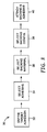
- FIG. 3 is a process flow diagram for making an indicator of the invention having the desired characteristics.
- the method of the invention provides a quick, easy, and reliable means to indicate whether a surface is properly prepared to receive a coating, for example, a primer, paint, or an adhesive of choice.
- a specifically designed permanently deformable indicator for example, in the form of a strip, is bonded to the surface of the substrate to be tested.
- a method for designing such an indicator strip is described below. The bonded indicator strip is pulled in an effort to remove it. If the specifically designed indicator strip yields or permanently deforms while being pulled away from the substrate, the surface would be considered properly prepared. However, if the specifically prepared test strip is pulled away from the surface before the indicator strip permanently deforms, the surface would be considered not properly prepared and further preparation, for example, cleaning, would be required.
- FIG. 1 shows one embodiment of a specifically prepared indicator that permanently deforms at an applied force.
- the indicator 10 comprises a backing 12 made from a material that has a yield point and an adhesive 14 on the backing.
- the indicator is generally “dogbone” shaped.
- FIG. 2 shows a depiction of an indicator 20 after it has been permanently deformed from an applied stress.
- FIG. 3 shows a flow diagram 30 of a process to design a specifically designed adhesion or surface preparation indicator.
- the process comprises the steps of: defining the target adhesion force 32 for a particular surface; selecting a suitable adhesive 34 ; selecting a material that permanently deforms under an applied stress 36 ; selecting a backing configuration that permanently deforms at the applied target adhesion force but does not permanently deform below the target adhesion force 38 ; and attaching the adhesive to the selected backing 40 so to form an indicator.
- the target adhesion force is typically set by a specification or requirement set by a party such as a customer.
- an adhesive film specification may be an adhesion or peel strength of 0.11 pounds force per inch width for a particular substrate.
- the target adhesion force may also be determined by measurement. For example, a coating may be applied to a substrate and then the force required to remove a specified area of the coating could be measured using a simple scale or a sophisticated machine such as an INSTRON brand instrument.
- a “suitable” adhesive is an adhesive that meets or exceeds the target adhesion force after attachment to the substrate when the surface of the substrate is properly prepared (acceptable), for example, clean, and/or an adhesive that does not meet the target adhesion force when the surface of the substrate is not properly prepared (not acceptable), for example, dirty or contaminated.
- acceptable for example, clean
- the suitable adhesive for the indicator may be the same or different than the adhesive or coating that will be used to bond to or coat the substrate.
- a suitable adhesive may also be identified through simple testing of the adhesion force of different adhesives on “clean” surfaces and on “dirty” surfaces as described above for determining the target adhesion force.
- a suitable adhesive is also an adhesive that forms a bond with the backing material, discussed below, such that the bond between the adhesive and the backing material does not fail, that is, separate, below the target adhesion force when pulling on the indicator.
- the bond strength between adhesives and proposed backing materials can easily be determined by bonding samples together and then measuring the adhesion force between them. If the adhesion force is below that of the target adhesion force, another adhesive and/or film and adhesive combination may be tested until the desired target adhesion force is met.
- the adhesive selected may be pressure sensitive, hot melt, curable, thermoset, contact, thermoplastic, crosslinking, or any combination of these.
- Specific examples include acrylics, epoxies, urethanes, amides, natural or synthetic rubbers, olefins, cyanoacrylates, silicones, and the like and combinations thereof.
- the step of selecting a material that permanently deforms or yields under an applied stress may be performed simply by selecting materials, for example, polymer films, and applying a stress to them and noting whether they have a yield point, that is, the material permanently deforms after applying stress or stretching it.
- the yield point of the material should bear some relationship to the target adhesion point. In other words, one probably would not select a material having a yield point of 10 grams force where the target adhesion force is, for example, 0.01 grams per specified width.
- Examples of materials that have a yield point are polyethylene, polypropylene, plasticized polyvinyl chloride, and terpolymers of vinylidine fluoride, hexafluoropropylene, and tetrafluoroethylene sold under the designation “THV 500”, available from 3M Company, St. Paul, Minn., and the like and combinations thereof.
- a backing configuration that permanently deforms at the applied target adhesion force but does not permanently deform at applied forces below the target adhesion force is selected.
- One means of selecting such a configuration is to cut a piece of the backing material having a certain cross-sectional area (thickness and width) and then measuring the force required to permanently deform that sample. Then, the shape and/or thickness of the backing material can be modified as (or if) required to achieve the yield point that matches the target adhesive force. For example, increasing the cross-sectional area of the sample will likely increase the force required for the material to reach its yield point, while decreasing the cross-sectional area will likely decrease the amount of force needed to reach the yield point.
- the cross-sectional area may be changed by increasing or decreasing the width and/or thickness of the sample.
- Backing thickness generally ranges from about 0.5 to about 50 mil and may be any whole or fractional thickness between 0.5 and 50 mil.
- the force required to reach the yield point for a given backing material should be substantially the same as the target adhesion force and preferably, not below the target adhesion force (assuming that the adhesive does not alter the yield point of the backing). “Substantially the same” means, for a particular backing material, within the experimental error as determined by a generally accepted materials testing protocol in the relevant art.
- the force required to reach the yield point of the backing material may be above the target adhesion force. However, the higher the yield point force is above the target adhesion force, the more likely it is to obtain false indications of un-properly prepared surfaces.
- Typical yield forces range from about 0.1 to about 20 pounds force and may be any whole or fractional value in between 0.1 and 20 pounds force.
- the suitable adhesive is bonded to the backing. This may be done by any of the known bonding methods, for example, solvent coating, hot melt coating, lamination, extrusion, etc., and may include treating the surface of the backing with a primer, by corona exposure, electron beam, and the like.
- the adhesive may be in the form of a liquid, powder, solid, or film. The adhesive may be coated over the full or a partial area of the appropriate backing surface.
- the substrates may be comprised of any material to which an adhesive (as defined) will form a bond with. Examples include, metals, glass, plastics, ceramics, masonry, plaster, paper, wood, fiber reinforced plastics, and the like and combinations thereof.
- the indicator used in Example 2 was designed as follows:
- the target adhesion force was defined as 40 ounces per inch width at ambient temperature 32 .
- An acrylic pressure-sensitive adhesive which adhered to a cleaned aluminum surface at a force of greater than 40 ounces per inch width and at a force of less than the target force when the surface was contaminated was selected by testing the adhesion performance of a plurality of acrylic adhesive compositions known to provide adhesion to aluminum surfaces 34 .
- a fluoropolymer thermoplastic film was selected as the permanently deformable backing material based on knowledge of the film's physical characteristics, for example, having a yield point, and being bondable to an acrylic adhesive 36 .
- the film configuration was selected by testing the yield points of film strips having a uniform width of 1 inch; a partial width of 3 ⁇ 4 inch, a partial width of 1 ⁇ 4 inch, a partial width of 1 ⁇ 2 inch, and a partial width of 5 ⁇ 8 inch. Partial width refers to the narrow portion of the dogbone shape.
- the selected adhesive was then coated onto the selected backing and dried, and the indicator was configured to the final form 40 .
- Surface preparation indicators were prepared by coating the primed surface of a yielding polymer film (3951 Surface Protection film, 3.5 mil, available from 3M Company) with a layer of acrylic pressure-sensitive adhesive and a release liner was applied to the exposed surface of the pressure-sensitive adhesive.
- the polymer film/adhesive/release liner construct was then cut into specimens using a die.
- the resulting specimens were dogbone shaped, having dimensions of 1 inch ⁇ 7 inches, with a 0.5 inch wide by 1 inch long neck beginning 1 inch from one end of the test strip.
- the adhesive was prepared by mixing 70 parts by weight isooctyl acrylate, 56 parts by weight ethyl acrylate, 14 parts by weight acrylic acid, 260 grams ethyl acetate, and 0.42 grams benzoyl peroxide in a container with nitrogen purging. The container was sealed and rotated in a water bath at 59° C. for 24 hours. The resulting solution was diluted to 21% solids with heptane. Next, 2.1 parts of a 5% (w/w) solution of N,N′-bis-1,2-propyleneisophthalamide in toluene was added prior to coating onto the yielding polymer film. The adhesive was dried in a convection oven set at 200° F. for 10 minutes.
- a specimen was applied by peeling back the release liner from the adhesive and then attaching the strip adhesive down to a 2024-T3 bare aluminum surface that had been cleaned with isopropanol.
- the specimen was removed by hand by pulling on the end of the specimen nearest the dogbone at an angle of about 180 degrees at a rate of about 12 inch/minute. The specimen yielded, thus indicating correct surface preparation.
- Example 2 The procedure of Example 2 was repeated except the surface of the aluminum panel was contaminated with a detergent after it had been properly cleaned. The specimen was removed from the substrate without yielding.
Abstract
The present invention relates to indicators of surface preparation and methods of making such indicators.
Description
The present invention relates to indicators of surface preparation and methods of making such indicators.
Typically, the application of coatings to a surface of a substrate requires proper surface preparation to provide adequate bonding between the coating and the surface. Examples of such coatings include paints, adhesives, primers, and the like. Surface preparation is performed to remove surface contaminates such as dust, fluids, oils, dirt, and the like, to obtain a desired surface cleanliness and/or to improve adhesion of the coating to the surface. A properly prepared surface may also be contaminated prior to the application of the coating. It would be desirable to provide an easy, inexpensive way of testing a surface just prior to the application of a coating or adherent to determine if additional surface preparation is required to provide an adequate bond between the surface and the coating.
In one embodiment, the invention provides a method of directly indicating the propensity of an adherent or coating to bond to a surface of a substrate. The steps of the method comprise applying a surface preparation indicator to the surface of the substrate wherein the substrate has a desired or target adhesion force to a coating. The surface preparation indicator comprises a polymeric backing material having a yield point and an adhesive on the backing. The target adhesive force and the force required to reach the yield point of the indicator are substantially the same.
In another embodiment, the invention provides a method of designing a surface preparation indicator for a particular substrate and adherent or coating combination. This method comprises the steps of providing a target adhesion force for the adherent to an acceptable surface of a substrate; selecting an adhesive that provides an adhesion to the acceptable surface that is equal to or greater than the target adhesion force and that provides an adhesion that is less than the target adhesion force when the surface of the substrate is not acceptable; selecting a backing material having a yield point and that bonds to the selected adhesive such that the backing material and the adhesive will not separate when subject to applied force that is lower than that of the target adhesion force; configuring said backing material such that the applied force required to reach the yield point is substantially the same as the target adhesion force; and bonding the selected adhesive to the backing material.
A “yield point” is the point at which, after an initial applied stress, a further applied stress causes appreciable elongation or yield in a material without the application of comparable additional stress. In other words, a “yield point” is the point at which, after an initial applied stress, appreciable elongation or yield in a material is obtained without the application of comparable additional stress. A material stressed beyond its yield point will have permanent deformation.
“Adhesive” means any substance that is capable of bonding to other materials by surface attachment.
FIG. 1 is a plan view of one embodiment of the invention.
FIG. 2 is plan view of an embodiment of the invention after yielding.
FIG. 3 is a process flow diagram for making an indicator of the invention having the desired characteristics.
In general, the method of the invention provides a quick, easy, and reliable means to indicate whether a surface is properly prepared to receive a coating, for example, a primer, paint, or an adhesive of choice. Simply, a specifically designed permanently deformable indicator, for example, in the form of a strip, is bonded to the surface of the substrate to be tested. A method for designing such an indicator strip is described below. The bonded indicator strip is pulled in an effort to remove it. If the specifically designed indicator strip yields or permanently deforms while being pulled away from the substrate, the surface would be considered properly prepared. However, if the specifically prepared test strip is pulled away from the surface before the indicator strip permanently deforms, the surface would be considered not properly prepared and further preparation, for example, cleaning, would be required.
FIG. 1 shows one embodiment of a specifically prepared indicator that permanently deforms at an applied force. The indicator 10 comprises a backing 12 made from a material that has a yield point and an adhesive 14 on the backing. The indicator is generally “dogbone” shaped.
FIG. 2 shows a depiction of an indicator 20 after it has been permanently deformed from an applied stress.
FIG. 3 shows a flow diagram 30 of a process to design a specifically designed adhesion or surface preparation indicator. Generally, the process comprises the steps of: defining the target adhesion force 32 for a particular surface; selecting a suitable adhesive 34; selecting a material that permanently deforms under an applied stress 36; selecting a backing configuration that permanently deforms at the applied target adhesion force but does not permanently deform below the target adhesion force 38; and attaching the adhesive to the selected backing 40 so to form an indicator.
The target adhesion force is typically set by a specification or requirement set by a party such as a customer. For example, an adhesive film specification may be an adhesion or peel strength of 0.11 pounds force per inch width for a particular substrate. The target adhesion force may also be determined by measurement. For example, a coating may be applied to a substrate and then the force required to remove a specified area of the coating could be measured using a simple scale or a sophisticated machine such as an INSTRON brand instrument.
A “suitable” adhesive is an adhesive that meets or exceeds the target adhesion force after attachment to the substrate when the surface of the substrate is properly prepared (acceptable), for example, clean, and/or an adhesive that does not meet the target adhesion force when the surface of the substrate is not properly prepared (not acceptable), for example, dirty or contaminated. Of course, the determination of a properly prepared surface and an un-properly prepared surface is typically determined by trial and error before an adhesive is selected. The suitable adhesive for the indicator may be the same or different than the adhesive or coating that will be used to bond to or coat the substrate. A suitable adhesive may also be identified through simple testing of the adhesion force of different adhesives on “clean” surfaces and on “dirty” surfaces as described above for determining the target adhesion force.
A suitable adhesive is also an adhesive that forms a bond with the backing material, discussed below, such that the bond between the adhesive and the backing material does not fail, that is, separate, below the target adhesion force when pulling on the indicator. The bond strength between adhesives and proposed backing materials can easily be determined by bonding samples together and then measuring the adhesion force between them. If the adhesion force is below that of the target adhesion force, another adhesive and/or film and adhesive combination may be tested until the desired target adhesion force is met.
The adhesive selected may be pressure sensitive, hot melt, curable, thermoset, contact, thermoplastic, crosslinking, or any combination of these. Specific examples include acrylics, epoxies, urethanes, amides, natural or synthetic rubbers, olefins, cyanoacrylates, silicones, and the like and combinations thereof.
The step of selecting a material that permanently deforms or yields under an applied stress may be performed simply by selecting materials, for example, polymer films, and applying a stress to them and noting whether they have a yield point, that is, the material permanently deforms after applying stress or stretching it. The yield point of the material should bear some relationship to the target adhesion point. In other words, one probably would not select a material having a yield point of 10 grams force where the target adhesion force is, for example, 0.01 grams per specified width. Examples of materials that have a yield point are polyethylene, polypropylene, plasticized polyvinyl chloride, and terpolymers of vinylidine fluoride, hexafluoropropylene, and tetrafluoroethylene sold under the designation “THV 500”, available from 3M Company, St. Paul, Minn., and the like and combinations thereof.
Once a material having a yield point is selected, a backing configuration that permanently deforms at the applied target adhesion force but does not permanently deform at applied forces below the target adhesion force is selected. One means of selecting such a configuration is to cut a piece of the backing material having a certain cross-sectional area (thickness and width) and then measuring the force required to permanently deform that sample. Then, the shape and/or thickness of the backing material can be modified as (or if) required to achieve the yield point that matches the target adhesive force. For example, increasing the cross-sectional area of the sample will likely increase the force required for the material to reach its yield point, while decreasing the cross-sectional area will likely decrease the amount of force needed to reach the yield point. The cross-sectional area may be changed by increasing or decreasing the width and/or thickness of the sample. Thus, one could construct correlation charts for each particular backing material that may be of interest. Backing thickness generally ranges from about 0.5 to about 50 mil and may be any whole or fractional thickness between 0.5 and 50 mil.
The force required to reach the yield point for a given backing material should be substantially the same as the target adhesion force and preferably, not below the target adhesion force (assuming that the adhesive does not alter the yield point of the backing). “Substantially the same” means, for a particular backing material, within the experimental error as determined by a generally accepted materials testing protocol in the relevant art. The force required to reach the yield point of the backing material may be above the target adhesion force. However, the higher the yield point force is above the target adhesion force, the more likely it is to obtain false indications of un-properly prepared surfaces.
Typical yield forces range from about 0.1 to about 20 pounds force and may be any whole or fractional value in between 0.1 and 20 pounds force.
Once a backing configuration is selected, the suitable adhesive is bonded to the backing. This may be done by any of the known bonding methods, for example, solvent coating, hot melt coating, lamination, extrusion, etc., and may include treating the surface of the backing with a primer, by corona exposure, electron beam, and the like. The adhesive may be in the form of a liquid, powder, solid, or film. The adhesive may be coated over the full or a partial area of the appropriate backing surface.
The substrates may be comprised of any material to which an adhesive (as defined) will form a bond with. Examples include, metals, glass, plastics, ceramics, masonry, plaster, paper, wood, fiber reinforced plastics, and the like and combinations thereof.
The indicator used in Example 2 was designed as follows:
The target adhesion force was defined as 40 ounces per inch width at ambient temperature 32. An acrylic pressure-sensitive adhesive which adhered to a cleaned aluminum surface at a force of greater than 40 ounces per inch width and at a force of less than the target force when the surface was contaminated was selected by testing the adhesion performance of a plurality of acrylic adhesive compositions known to provide adhesion to aluminum surfaces 34. A fluoropolymer thermoplastic film was selected as the permanently deformable backing material based on knowledge of the film's physical characteristics, for example, having a yield point, and being bondable to an acrylic adhesive 36. The film configuration was selected by testing the yield points of film strips having a uniform width of 1 inch; a partial width of ¾ inch, a partial width of ¼ inch, a partial width of ½ inch, and a partial width of ⅝ inch. Partial width refers to the narrow portion of the dogbone shape. The selected adhesive was then coated onto the selected backing and dried, and the indicator was configured to the final form 40.
Surface preparation indicators were prepared by coating the primed surface of a yielding polymer film (3951 Surface Protection film, 3.5 mil, available from 3M Company) with a layer of acrylic pressure-sensitive adhesive and a release liner was applied to the exposed surface of the pressure-sensitive adhesive. The polymer film/adhesive/release liner construct was then cut into specimens using a die. The resulting specimens were dogbone shaped, having dimensions of 1 inch×7 inches, with a 0.5 inch wide by 1 inch long neck beginning 1 inch from one end of the test strip.
The adhesive was prepared by mixing 70 parts by weight isooctyl acrylate, 56 parts by weight ethyl acrylate, 14 parts by weight acrylic acid, 260 grams ethyl acetate, and 0.42 grams benzoyl peroxide in a container with nitrogen purging. The container was sealed and rotated in a water bath at 59° C. for 24 hours. The resulting solution was diluted to 21% solids with heptane. Next, 2.1 parts of a 5% (w/w) solution of N,N′-bis-1,2-propyleneisophthalamide in toluene was added prior to coating onto the yielding polymer film. The adhesive was dried in a convection oven set at 200° F. for 10 minutes.
A specimen was applied by peeling back the release liner from the adhesive and then attaching the strip adhesive down to a 2024-T3 bare aluminum surface that had been cleaned with isopropanol. The specimen was removed by hand by pulling on the end of the specimen nearest the dogbone at an angle of about 180 degrees at a rate of about 12 inch/minute. The specimen yielded, thus indicating correct surface preparation.
The procedure of Example 2 was repeated except the surface of the aluminum panel was contaminated with a detergent after it had been properly cleaned. The specimen was removed from the substrate without yielding.
While the specification has been described in detail with respect to specific embodiments thereof, it will be appreciated that those skilled in the art, upon attaining an understanding of the foregoing, may readily conceive of alterations to, variations of, and equivalents to these embodiments. Accordingly, the scope of the present invention should be assessed as that of the appended claims and any equivalents thereto.
Claims (13)
1. A method of directly indicating the propensity of an adherent to bond to a surface of a substrate comprising the steps of:
applying a surface preparation indicator to the surface of the substrate wherein the substrate has a target adhesion force, said surface preparation indicator comprising a polymeric backing material having a yield point and having an adhesive thereon and having a thickness, width, and length, wherein the target adhesive force and the force required to reach the yield point are substantially the same; and
applying force to said indicator until the indicator either reaches the yield point or is removed from the substrate.
2. The method of claim 1 , wherein the backing material comprises polyethylene, polypropylene, plasticized polyvinyl chloride, a terpolymer of vinylidine fluoride, hexafluoropropylene, and tetrafluoroethylene, and combinations thereof.
3. The method of claim 1 , wherein the adhesive comprises acrylics, epoxies, urethanes, amides, natural or synthetic rubbers, olefins, cyanoacrylates, silicones, and combinations thereof.
4. The method of claim 1 , wherein the surface preparation indicator consists essentially of a polymeric backing material having a yield point and having an adhesive on the backing film.
5. The method of claim 1 , wherein the force required to reach the yield point of the backing material is less than 50 pounds force.
6. The method of claim 1 , wherein the surface of the substrate comprises metal.
7. The method of claim 1 , wherein the surface of the substrate is selected from the group consisting of metals, glass, plastics, ceramics, masonry, plaster, paper, wood, fiber reinforced plastics, and combinations thereof.
8. The method of claim 1 , wherein the force required to reach the yield point of the backing material is greater than 0.1 pounds force.
9. The method of claim 1 , wherein the surface preparation indicator has a non-uniform width along its length.
10. The method of claim 1 , wherein the step of applying the indicator to a surface of the substrate indicates application of pressure.
11. The method of claim 1 , wherein the adhesive is a pressure-sensitive adhesive at the application temperature.
12. The method of claim 1 , wherein the adhesive is a pressure-sensitive adhesive at ambient temperature.
13. The method of claim 1 , wherein the step of applying force comprises a 180 degree peel procedure.
Priority Applications (1)
| Application Number | Priority Date | Filing Date | Title |
|---|---|---|---|
| US10/211,361 US6800156B2 (en) | 2002-08-02 | 2002-08-02 | Surface preparation indicators |
Applications Claiming Priority (1)
| Application Number | Priority Date | Filing Date | Title |
|---|---|---|---|
| US10/211,361 US6800156B2 (en) | 2002-08-02 | 2002-08-02 | Surface preparation indicators |
Publications (2)
| Publication Number | Publication Date |
|---|---|
| US20040020592A1 US20040020592A1 (en) | 2004-02-05 |
| US6800156B2 true US6800156B2 (en) | 2004-10-05 |
Family
ID=31187559
Family Applications (1)
| Application Number | Title | Priority Date | Filing Date |
|---|---|---|---|
| US10/211,361 Expired - Fee Related US6800156B2 (en) | 2002-08-02 | 2002-08-02 | Surface preparation indicators |
Country Status (1)
| Country | Link |
|---|---|
| US (1) | US6800156B2 (en) |
Cited By (2)
| Publication number | Priority date | Publication date | Assignee | Title |
|---|---|---|---|---|
| US7506450B2 (en) | 2006-06-30 | 2009-03-24 | The Stanley Works | Adhesive mount for a leveling device and a leveling device |
| US20100015455A1 (en) * | 2008-07-21 | 2010-01-21 | United Technologies Corporation | Method and assembly for validating bond line |
Families Citing this family (2)
| Publication number | Priority date | Publication date | Assignee | Title |
|---|---|---|---|---|
| WO2008000857A1 (en) * | 2006-06-30 | 2008-01-03 | Airbus España, S.L. | Method for monitoring the quality of a structural adhesively bonded join |
| IT1394333B1 (en) * | 2009-04-14 | 2012-06-06 | Del Sarto | ADHESIVE ELEMENT FOR MEMBERSHIP TEST AND ITS TEST PROCEDURE |
Citations (3)
| Publication number | Priority date | Publication date | Assignee | Title |
|---|---|---|---|---|
| US4188824A (en) | 1978-06-02 | 1980-02-19 | Youngstown Sheet And Tube Company | Coating adherence prospensity testing of metal substrates |
| US5516581A (en) | 1990-12-20 | 1996-05-14 | Minnesota Mining And Manufacturing Company | Removable adhesive tape |
| US5649447A (en) | 1996-07-25 | 1997-07-22 | The Boeing Company | Non destructive paint and bonding adhesion prediction meter (APM) for metal surfaces |
-
2002
- 2002-08-02 US US10/211,361 patent/US6800156B2/en not_active Expired - Fee Related
Patent Citations (3)
| Publication number | Priority date | Publication date | Assignee | Title |
|---|---|---|---|---|
| US4188824A (en) | 1978-06-02 | 1980-02-19 | Youngstown Sheet And Tube Company | Coating adherence prospensity testing of metal substrates |
| US5516581A (en) | 1990-12-20 | 1996-05-14 | Minnesota Mining And Manufacturing Company | Removable adhesive tape |
| US5649447A (en) | 1996-07-25 | 1997-07-22 | The Boeing Company | Non destructive paint and bonding adhesion prediction meter (APM) for metal surfaces |
Cited By (5)
| Publication number | Priority date | Publication date | Assignee | Title |
|---|---|---|---|---|
| US7506450B2 (en) | 2006-06-30 | 2009-03-24 | The Stanley Works | Adhesive mount for a leveling device and a leveling device |
| US7685724B2 (en) | 2006-06-30 | 2010-03-30 | The Stanley Works | Leveling device |
| US7927450B2 (en) | 2006-06-30 | 2011-04-19 | Stanley Black Decker, Inc. | Method of manufacturing an adhesive mount for a leveling device |
| US20100015455A1 (en) * | 2008-07-21 | 2010-01-21 | United Technologies Corporation | Method and assembly for validating bond line |
| US8349104B2 (en) | 2008-07-21 | 2013-01-08 | United Technologies Corporation | Method and assembly for validating bond line |
Also Published As
| Publication number | Publication date |
|---|---|
| US20040020592A1 (en) | 2004-02-05 |
Similar Documents
| Publication | Publication Date | Title |
|---|---|---|
| TWI241332B (en) | Crosslinked pressure sensitive adhesive compositions, and adhesive articles based thereon, useful in high temperature applications | |
| JP5725323B2 (en) | Protective adhesive film | |
| JP5015648B2 (en) | Optical pressure-sensitive adhesive composition and optical functional film | |
| CN107076918B (en) | Polarizing coating with adhesive phase, its manufacturing method and image display device | |
| JP2004514016A (en) | Pressure-sensitive adhesive with high yield strength | |
| TWI582194B (en) | An article comprising a film on a carrier or release substrate | |
| JP6390034B2 (en) | Adhesive sheet | |
| CN108602312B (en) | Conformable, stretch releasable adhesive articles | |
| US6800156B2 (en) | Surface preparation indicators | |
| US20230002646A1 (en) | Electrically conductive masking tape | |
| JP7066331B2 (en) | Double-sided pressure-sensitive adhesive tape | |
| JP2010150498A (en) | Protective sheet and use thereof | |
| JPH09221649A (en) | Pressure sensitive adhesive and surface protecting material | |
| KR20020035865A (en) | Adhesive sheet and coating adhesive sheet | |
| McKnight et al. | Measuring peel adhesion of coatings | |
| US20040021312A1 (en) | Security label | |
| Picard et al. | Bonding of silicone rubbers on metal (2) physical chemistry of adhesion | |
| JP2005336680A (en) | Fixing material and fixing tape for wig | |
| WO2019203004A1 (en) | Adhesive tape and article | |
| JP2584918B2 (en) | Release sheet | |
| JP4394757B2 (en) | Pressure sensitive adhesive and surface protective material | |
| TWI774918B (en) | Temperature-sensitive adhesive, temperature-sensitive adhesive sheet and temperature-sensitive adhesive tape | |
| KR101862447B1 (en) | Non-crosslinkable adhesive composition, and adhesive sheet | |
| JPH02232547A (en) | Method and apparatus for measuring peeling force or unwinding force for adhesive tape or adhesive sheet | |
| US9864112B1 (en) | Conformable retroreflective graphic film |
Legal Events
| Date | Code | Title | Description |
|---|---|---|---|
| AS | Assignment |
Owner name: 3M INNOVATIVE PROPERTIES COMPANY, MINNESOTA Free format text: ASSIGNMENT OF ASSIGNORS INTEREST;ASSIGNORS:DIETZ, TIMOTHY M.;FLEISCHHACKER, GERALD F.;HEBERT, LARRY S.;AND OTHERS;REEL/FRAME:013439/0543;SIGNING DATES FROM 20021008 TO 20021022 |
|
| FPAY | Fee payment |
Year of fee payment: 4 |
|
| REMI | Maintenance fee reminder mailed | ||
| REMI | Maintenance fee reminder mailed | ||
| LAPS | Lapse for failure to pay maintenance fees | ||
| STCH | Information on status: patent discontinuation |
Free format text: PATENT EXPIRED DUE TO NONPAYMENT OF MAINTENANCE FEES UNDER 37 CFR 1.362 |
|
| FP | Lapsed due to failure to pay maintenance fee |
Effective date: 20121005 |