US6799854B1 - Binoculars, telescope or the like with protective lens cap articulated to the front of the lens - Google Patents
Binoculars, telescope or the like with protective lens cap articulated to the front of the lens Download PDFInfo
- Publication number
- US6799854B1 US6799854B1 US10/465,629 US46562903A US6799854B1 US 6799854 B1 US6799854 B1 US 6799854B1 US 46562903 A US46562903 A US 46562903A US 6799854 B1 US6799854 B1 US 6799854B1
- Authority
- US
- United States
- Prior art keywords
- binoculars
- telescope
- lens
- protective lens
- lens cap
- Prior art date
- Legal status (The legal status is an assumption and is not a legal conclusion. Google has not performed a legal analysis and makes no representation as to the accuracy of the status listed.)
- Expired - Fee Related
Links
Images


Classifications
-
- G—PHYSICS
- G02—OPTICS
- G02B—OPTICAL ELEMENTS, SYSTEMS OR APPARATUS
- G02B23/00—Telescopes, e.g. binoculars; Periscopes; Instruments for viewing the inside of hollow bodies; Viewfinders; Optical aiming or sighting devices
- G02B23/16—Housings; Caps; Mountings; Supports, e.g. with counterweight
Definitions
- the invention relates to a pair of binoculars, a telescope of the like, comprising a protective lens cap articulated to a front of the lens.
- this object is attained in that a pivot joint is formed between the edge of the lens and the protective lens cap, in use having a substantially horizontal pivot axis and a substantially vertical pivot axis.
- the design according to the invention enables the protective lens cap to be swung upwards in a manner known per se about a substantially horizontal pivot axis, and then, by rotation about the substantially vertical pivot axis in particular by 180°, to be swivelled with the inside turned towards a user's face, and then to be folded down on the top or bottom of the optical instrument where it is reliably secured and does not interfere with observation.
- the pivot joint arrangement in the vicinity of the edge of the lens, comprises a substantially horizontal pivot joint and, further outwards, a substantially vertical pivot joint i.e., two successive, separate pivot joints.
- the pivot joint arrangement is a ball-and-socket joint so that the horizontal and the vertical pivot axes combine and are comprised in a single joint arrangement, which ensures highly economic manufacture and advantageous final assembly by reason of the snap-in locking that is feasible in such a ball-and-socket joint.
- the pivot joint arrangement may further be embodied for defined internal friction or locking such that the protective lens cap can be positioned in a stable stop position i.e., no special locking mechanisms are needed on the top surface of the casing, keeping the protective caps in the stop position folded down on the top surface.
- the protective lens caps when removed from the lens and swung out, serve as a support for the optical instrument when it is put down, this offering another possibility of use of the caps which reliably preclude any damages to the instrument when it is put down and make it easier to lift the instrument by producing a distance from where it is put down.
- FIG. 1 is a perspective view of the area of a lens of a pair of binoculars
- FIG. 2 is a longitudinal section of the area of the lens
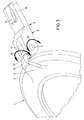
- FIG. 3 is a perspective view, on an enlarged scale, of the pivot joint of the protective lens cap.
- the drawing illustrates the area of a lens of a pair of binoculars 1 , the lens 2 being covered by a pivotable protective lens cap 3 .
- the protective lens cap 3 comprises an attachment 6 , which enclasps the outer edge 4 of the cap 3 by means of a crimp 5 and has a pivot bearing bolt 7 molded on integrally, the bolt 7 running crosswise of the crimp 5 and engaging with the forked end 8 of a joining piece 9 ; in this way a pivot bearing is formed, the bearing axis of which corresponds to the central longitudinal axis of the bearing bolt 7 i.e., a pivot bearing with a substantially horizontal pivot axis in the condition of use, ensuring a pivoted motion in the direction of the arrow 10 of FIG. 3 .
- the end 11 of the crimp 5 includes a widened cylindrical fitting 12 which is topped by a pivot bearing bolt 13 of reduced diameter which engages with a drilled hole 14 of the pivot bearing bolt 7 (see FIG. 2 ), in this way forming a pivot bearing around a substantially vertical pivot axis which enables the protective lens cap 3 to swivel in the direction of the arrow 15 of FIG. 3 .
- the free end of the joining piece 9 comprises a locking piece 16 with a snap-in pin 17 , the locking piece 16 snap-engaging with a locking ring 18 for securing the protective lens cap 3 on the casing ( 21 ) in the vicinity of the lens 2 of the binoculars 1 , as seen in FIG. 2 .
- the snap-in pin 17 touches the top surface 19 of the locking ring 18 from behind. This locking engagement may be released when the rubber coating 20 is pressed.
- the design according to the invention enables the protective lens cap 3 to be releasably secured to the binoculars 1 in the vicinity of the lens 2 .
- the protective lens cap When secured, the protective lens cap can be swung upwards from the closed condition about the substantially horizontal pivot axis in the direction of the arrow 10 and, when approximately parallel to the lens 2 , it can be pivoted by 180° about the substantially vertical axis in the direction of the arrow 15 so that the inside of the protective lens cap, originally facing the lens 2 , is turned towards a user's face, and the protective lens cap 3 may then again be pivoted about the substantially horizontal pivot axis in the direction of the arrow 10 , as seen in FIG. 2, and folded down on the top surface of the binoculars 1 in the vicinity of the lens 2 .
- the protective lens cap does not interfere in any way with observation.
- the binoculars can be put down with the protective lens cap downwards, ensuring gentle handling and easy lifting of the binoculars.
Landscapes
- Physics & Mathematics (AREA)
- Astronomy & Astrophysics (AREA)
- General Physics & Mathematics (AREA)
- Optics & Photonics (AREA)
- Telescopes (AREA)
Abstract
Description
Claims (5)
Priority Applications (1)
| Application Number | Priority Date | Filing Date | Title |
|---|---|---|---|
| US10/465,629 US6799854B1 (en) | 2003-06-20 | 2003-06-20 | Binoculars, telescope or the like with protective lens cap articulated to the front of the lens |
Applications Claiming Priority (1)
| Application Number | Priority Date | Filing Date | Title |
|---|---|---|---|
| US10/465,629 US6799854B1 (en) | 2003-06-20 | 2003-06-20 | Binoculars, telescope or the like with protective lens cap articulated to the front of the lens |
Publications (1)
| Publication Number | Publication Date |
|---|---|
| US6799854B1 true US6799854B1 (en) | 2004-10-05 |
Family
ID=33030113
Family Applications (1)
| Application Number | Title | Priority Date | Filing Date |
|---|---|---|---|
| US10/465,629 Expired - Fee Related US6799854B1 (en) | 2003-06-20 | 2003-06-20 | Binoculars, telescope or the like with protective lens cap articulated to the front of the lens |
Country Status (1)
| Country | Link |
|---|---|
| US (1) | US6799854B1 (en) |
Cited By (18)
| Publication number | Priority date | Publication date | Assignee | Title |
|---|---|---|---|---|
| US20060218841A1 (en) * | 2004-11-10 | 2006-10-05 | Leupold & Stevens, Inc. | Pivoting lens covers for riflescopes and the like |
| US20070070205A1 (en) * | 2005-09-26 | 2007-03-29 | Chicony Electronics Co. Ltd. | Web cam |
| US20070183061A1 (en) * | 2006-02-08 | 2007-08-09 | Nikon Vision Co., Ltd. | Telescope and lens cap |
| US20080186584A1 (en) * | 2007-02-01 | 2008-08-07 | Marlin Daniel Ballard | Spring-biased multi-axis articulating lens cover |
| US20090002823A1 (en) * | 2007-06-30 | 2009-01-01 | David Law | Permanently-Affixed Lens Cap |
| US20090052034A1 (en) * | 2007-08-22 | 2009-02-26 | Zeck Donald A | Lens protection device |
| CN101114110B (en) * | 2006-07-27 | 2010-05-12 | 中强光电股份有限公司 | Lens cap device |
| US20100187417A1 (en) * | 2008-11-11 | 2010-07-29 | Phokus Research Group, Llc | Night vision instrument focus device |
| US20100302638A1 (en) * | 2009-06-02 | 2010-12-02 | Irvine Sensors Corporation | Repositionable lens cover |
| US8292523B2 (en) | 2010-08-04 | 2012-10-23 | Deluxgear, Llc | Protective cup lens cover |
| WO2014209675A1 (en) * | 2013-06-24 | 2014-12-31 | Michael Garber | Lens cap with integrated storage mechanism |
| US20150226960A1 (en) * | 2014-02-12 | 2015-08-13 | NcStar Inc. | Lens Cover |
| US9157586B1 (en) * | 2012-07-02 | 2015-10-13 | Edward Vose Babcock, IV | Light filtering system |
| US20150355453A1 (en) * | 2013-01-14 | 2015-12-10 | Krauss-Maffei Wegmann Gmbh & Co.Kg | Protective device for a lens |
| WO2016062801A1 (en) * | 2014-10-23 | 2016-04-28 | Thales | Sealing device with locking system |
| EP3367043A1 (en) * | 2017-02-27 | 2018-08-29 | Leica Camera AG | Protective cap |
| US11181675B2 (en) * | 2019-01-18 | 2021-11-23 | Armament Technology Inc. | Optical polarizer assembly |
| US20220074707A1 (en) * | 2020-06-03 | 2022-03-10 | Bushnell Inc. | Riflescope cap assembly |
Citations (11)
| Publication number | Priority date | Publication date | Assignee | Title |
|---|---|---|---|---|
| US2488188A (en) * | 1947-05-15 | 1949-11-15 | Earl H Halvorson | Telescopic sight protector |
| US2849795A (en) * | 1955-11-15 | 1958-09-02 | Royal A Vissing | Lens covers |
| US3840883A (en) | 1973-09-17 | 1974-10-08 | J Choate | Camera lens hood |
| US4641932A (en) | 1985-06-13 | 1987-02-10 | Wolfgang Harms | Protective lens cover for optical means |
| US4909617A (en) | 1987-10-26 | 1990-03-20 | Boyd Jeffrey M | Camera hood with pivoting lens cap |
| US5495676A (en) * | 1994-04-25 | 1996-03-05 | Blount, Inc. | Lens cap assembly and removal method |
| US5631772A (en) | 1994-09-30 | 1997-05-20 | Fuji Photo Optical Co., Ltd. | Telescope provided with automatically opening and closing cover |
| US5815316A (en) | 1997-08-29 | 1998-09-29 | The United States Of America As Represented By The Secretary Of The Army | Protection system and technique for electro-optical systems |
| US6088174A (en) * | 1999-03-03 | 2000-07-11 | The Brunton Company | Lens cap apparatus for optical instrument |
| US6247855B1 (en) * | 1998-01-29 | 2001-06-19 | Olympus Optical Co., Ltd. | Lens protection cover-attached camera |
| US6416189B1 (en) * | 2000-09-26 | 2002-07-09 | Christopher Michael Watson | Water-resistant, scope shade attachment apparatus |
-
2003
- 2003-06-20 US US10/465,629 patent/US6799854B1/en not_active Expired - Fee Related
Patent Citations (11)
| Publication number | Priority date | Publication date | Assignee | Title |
|---|---|---|---|---|
| US2488188A (en) * | 1947-05-15 | 1949-11-15 | Earl H Halvorson | Telescopic sight protector |
| US2849795A (en) * | 1955-11-15 | 1958-09-02 | Royal A Vissing | Lens covers |
| US3840883A (en) | 1973-09-17 | 1974-10-08 | J Choate | Camera lens hood |
| US4641932A (en) | 1985-06-13 | 1987-02-10 | Wolfgang Harms | Protective lens cover for optical means |
| US4909617A (en) | 1987-10-26 | 1990-03-20 | Boyd Jeffrey M | Camera hood with pivoting lens cap |
| US5495676A (en) * | 1994-04-25 | 1996-03-05 | Blount, Inc. | Lens cap assembly and removal method |
| US5631772A (en) | 1994-09-30 | 1997-05-20 | Fuji Photo Optical Co., Ltd. | Telescope provided with automatically opening and closing cover |
| US5815316A (en) | 1997-08-29 | 1998-09-29 | The United States Of America As Represented By The Secretary Of The Army | Protection system and technique for electro-optical systems |
| US6247855B1 (en) * | 1998-01-29 | 2001-06-19 | Olympus Optical Co., Ltd. | Lens protection cover-attached camera |
| US6088174A (en) * | 1999-03-03 | 2000-07-11 | The Brunton Company | Lens cap apparatus for optical instrument |
| US6416189B1 (en) * | 2000-09-26 | 2002-07-09 | Christopher Michael Watson | Water-resistant, scope shade attachment apparatus |
Non-Patent Citations (1)
| Title |
|---|
| Patent Abstracts of Japan, Publication No. 01097932, "Controller For Opening And Closing Barrier For Camera," Konica Corp, Apr. 17, 1989. |
Cited By (34)
| Publication number | Priority date | Publication date | Assignee | Title |
|---|---|---|---|---|
| US20060218841A1 (en) * | 2004-11-10 | 2006-10-05 | Leupold & Stevens, Inc. | Pivoting lens covers for riflescopes and the like |
| US7721480B2 (en) | 2004-11-10 | 2010-05-25 | Leupold & Stevens, Inc. | Pivoting lens covers for riflescopes and the like |
| US20070070205A1 (en) * | 2005-09-26 | 2007-03-29 | Chicony Electronics Co. Ltd. | Web cam |
| CN101017241B (en) * | 2006-02-08 | 2011-03-23 | 株式会社尼康美景 | Telescope and lens cap |
| US20070183061A1 (en) * | 2006-02-08 | 2007-08-09 | Nikon Vision Co., Ltd. | Telescope and lens cap |
| GB2435108A (en) * | 2006-02-08 | 2007-08-15 | Nikon Vision Co Ltd | Telescope and lens cap |
| GB2435108B (en) * | 2006-02-08 | 2009-04-22 | Nikon Vision Co Ltd | Telescope and lens cap |
| US7561349B2 (en) | 2006-02-08 | 2009-07-14 | Nikon Vision Co., Ltd. | Telescope and lens cap |
| CN101114110B (en) * | 2006-07-27 | 2010-05-12 | 中强光电股份有限公司 | Lens cap device |
| US7585080B2 (en) | 2007-02-01 | 2009-09-08 | Marlin Daniel Ballard | Spring-biased multi-axis articulating lens cover |
| US20080186584A1 (en) * | 2007-02-01 | 2008-08-07 | Marlin Daniel Ballard | Spring-biased multi-axis articulating lens cover |
| US20090002823A1 (en) * | 2007-06-30 | 2009-01-01 | David Law | Permanently-Affixed Lens Cap |
| US7682091B2 (en) | 2007-08-22 | 2010-03-23 | Zeck Donald A | Lens protection device |
| US20090052034A1 (en) * | 2007-08-22 | 2009-02-26 | Zeck Donald A | Lens protection device |
| US7969673B2 (en) * | 2008-11-11 | 2011-06-28 | Phokus Research Group, Llc | Night vision instrument focus device |
| US20100187417A1 (en) * | 2008-11-11 | 2010-07-29 | Phokus Research Group, Llc | Night vision instrument focus device |
| US8118439B2 (en) | 2009-06-02 | 2012-02-21 | Irvine Sensors Corp. | Repositionable lens cover |
| US20100302638A1 (en) * | 2009-06-02 | 2010-12-02 | Irvine Sensors Corporation | Repositionable lens cover |
| US8292523B2 (en) | 2010-08-04 | 2012-10-23 | Deluxgear, Llc | Protective cup lens cover |
| US9157586B1 (en) * | 2012-07-02 | 2015-10-13 | Edward Vose Babcock, IV | Light filtering system |
| US9746661B2 (en) * | 2013-01-14 | 2017-08-29 | Krauss-Maffei Wegmann Gmbh & Co. Kg | Protective device for a lens |
| US20150355453A1 (en) * | 2013-01-14 | 2015-12-10 | Krauss-Maffei Wegmann Gmbh & Co.Kg | Protective device for a lens |
| WO2014209675A1 (en) * | 2013-06-24 | 2014-12-31 | Michael Garber | Lens cap with integrated storage mechanism |
| US9563050B2 (en) * | 2014-02-12 | 2017-02-07 | N cSTAR, Inc. | Lens cover |
| US20150226960A1 (en) * | 2014-02-12 | 2015-08-13 | NcStar Inc. | Lens Cover |
| EP2908084A1 (en) * | 2014-02-12 | 2015-08-19 | NcSTAR Inc. | Lens cover |
| WO2016062801A1 (en) * | 2014-10-23 | 2016-04-28 | Thales | Sealing device with locking system |
| FR3027690A1 (en) * | 2014-10-23 | 2016-04-29 | Thales Sa | SHUT OFF DEVICE WITH LATCHING SYSTEM |
| EP3367043A1 (en) * | 2017-02-27 | 2018-08-29 | Leica Camera AG | Protective cap |
| US11181675B2 (en) * | 2019-01-18 | 2021-11-23 | Armament Technology Inc. | Optical polarizer assembly |
| US20220074707A1 (en) * | 2020-06-03 | 2022-03-10 | Bushnell Inc. | Riflescope cap assembly |
| US11609068B2 (en) * | 2020-06-03 | 2023-03-21 | Bushnell Inc. | Riflescope cap assembly |
| US20230168065A1 (en) * | 2020-06-03 | 2023-06-01 | Bushnell Inc. | Riflescope cap assembly |
| US11852440B2 (en) * | 2020-06-03 | 2023-12-26 | Bushnell Inc. | Riflescope cap assembly |
Similar Documents
| Publication | Publication Date | Title |
|---|---|---|
| US6799854B1 (en) | Binoculars, telescope or the like with protective lens cap articulated to the front of the lens | |
| US7240370B2 (en) | Cap attachable, adjustable sunglasses | |
| US7070273B2 (en) | Eyeglasses frame with rotatable temples | |
| CN2159033Y (en) | Goggles especially for industry or sport | |
| US7055218B2 (en) | Hinge | |
| US6935741B2 (en) | Eye shield attachment device and assembly | |
| US8517532B1 (en) | Eyewear with reversible folding temples | |
| CA2720589C (en) | Hat brim with rearview mirrors | |
| US7207673B1 (en) | Cap-mounted sun glasses | |
| CA2481159A1 (en) | Anti-fog visors assembly | |
| US7377636B2 (en) | Liftable eyeglasses | |
| CA2012026A1 (en) | Eyewear with rearview mirror | |
| US6755523B1 (en) | Glasses | |
| US20200344343A1 (en) | Handle for holding mobile devices with users fingers | |
| US6786594B1 (en) | Hinge for eyewear | |
| US5570492A (en) | Joint for eyeglass temples | |
| US20070090249A1 (en) | Hinge assembly having a torque device to provide an assistance to assist a pivotal movement of a display relative to a base of a laptop computer | |
| US20090168211A1 (en) | Auxiliary mirror assembly for sideview mirror of car | |
| US4620777A (en) | Sideview mirror with spring-loaded water shield for vehicle | |
| EP2689286A1 (en) | Eyewear. | |
| EP0732607B1 (en) | Joints for spectacles sides | |
| HK1068686B (en) | Binoculars, telescope or the like with protective lens cap articulated to the front of the lens | |
| JP2004325881A (en) | Binoculars having protective lens cap connected with front part of lens | |
| CN219613281U (en) | Rotatable cosmetic mirror | |
| CN217518448U (en) | Hidden abnormal shape apron flip structure |
Legal Events
| Date | Code | Title | Description |
|---|---|---|---|
| AS | Assignment |
Owner name: STEINER-OPTIK GMBH, GERMANY Free format text: ASSIGNMENT OF ASSIGNORS INTEREST;ASSIGNOR:STEINER, CARL;REEL/FRAME:014507/0455 Effective date: 20030414 |
|
| FPAY | Fee payment |
Year of fee payment: 4 |
|
| FEPP | Fee payment procedure |
Free format text: PAT HOLDER NO LONGER CLAIMS SMALL ENTITY STATUS, ENTITY STATUS SET TO UNDISCOUNTED (ORIGINAL EVENT CODE: STOL); ENTITY STATUS OF PATENT OWNER: LARGE ENTITY |
|
| REMI | Maintenance fee reminder mailed | ||
| LAPS | Lapse for failure to pay maintenance fees | ||
| STCH | Information on status: patent discontinuation |
Free format text: PATENT EXPIRED DUE TO NONPAYMENT OF MAINTENANCE FEES UNDER 37 CFR 1.362 |
|
| FP | Lapsed due to failure to pay maintenance fee |
Effective date: 20121005 |